To access CADD template files with predefined drafting
settings, go to the Student Companion Website, select
Student Downloads, Drafting Templates, and then the
appropriate template file. Use the templates to create new
designs, as a resource for drawing and model content, or
for inspiration when developing your own templates. Use
the ASME-Inch and ASME-Metric drafting templates that
follow ASME, ISO, and related mechanical drafting
standards for electronic drawing problems, unless
otherwise specified by your instructor. Use architectural-
style templates for electrical problems, unless otherwise
specified by your instructor. Drawing templates include
standard sheet sizes and formats, and a variety of
appropriate drawing settings and content. You can also use
a utility such as the AutoCAD DesignCenter to add content
from the drawing templates to your own drawings and
templates. Consult with your instructor to determine which
template drawing and drawing content to use.
DRAFTING TEMPLATES
CHAPTER 20 ELECTRICAL AND
ELECTRONIC DRAFTING PROBLEMS
INSTRUCTIONS
1. Read all instructions before you begin working, unless oth-
erwise specified by your instructor.
2. Use the attached engineering layouts to prepare each draw-
ing. Refer to chapter coverage for symbol and component
dimensions and refer to previous drawings for information
as you progress to each drawing.
3. Use an ASME Y14.1 or ASME Y14.1M standard border and
title block unless otherwise specified in the problem in-
structions or by your instructor.
4. Prepare well-balanced, easy-to-read drawings. Most draw-
ings have no scale.
5. Many of the following problems contain symbols that are
duplicated multiple times. These electrical problems dem-
onstrate the power of CADD when you create one symbol
and have the ability to use it several times on one or more
drawings.
6. Additional information is provided for some problems.
7. Estimate unknown dimensions based proportionally on
given features and dimensions.
59728_ch20_EOC_ptg01.indd 2 22/02/16 10:50 am
3
BASIC DIAGRAMS
Part 1 : Problems 20.1 Through 20.10
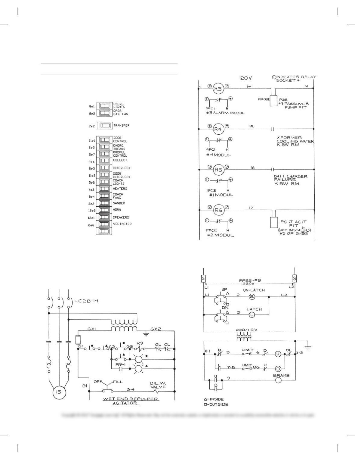
PROBLEM 20.1 Switch panel
PROBLEM 20.2 Schematic
PROBLEM 20.3 Schematic
PROBLEM 20.4 Schematic
59728_ch20_EOC_ptg01.indd 3 22/02/16 10:50 am
4
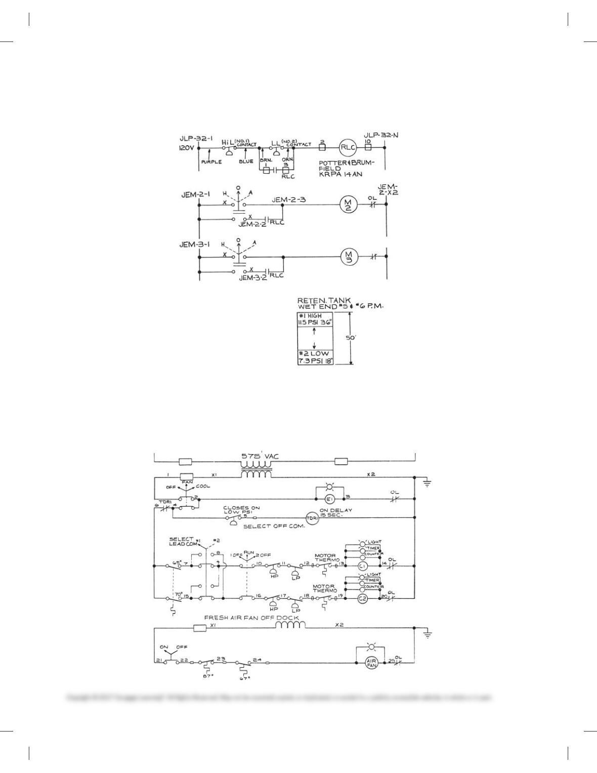
PROBLEM 20.5 Schematic
PROBLEM 20.6 Schematic
59728_ch20_EOC_ptg01.indd 4 22/02/16 10:50 am
5
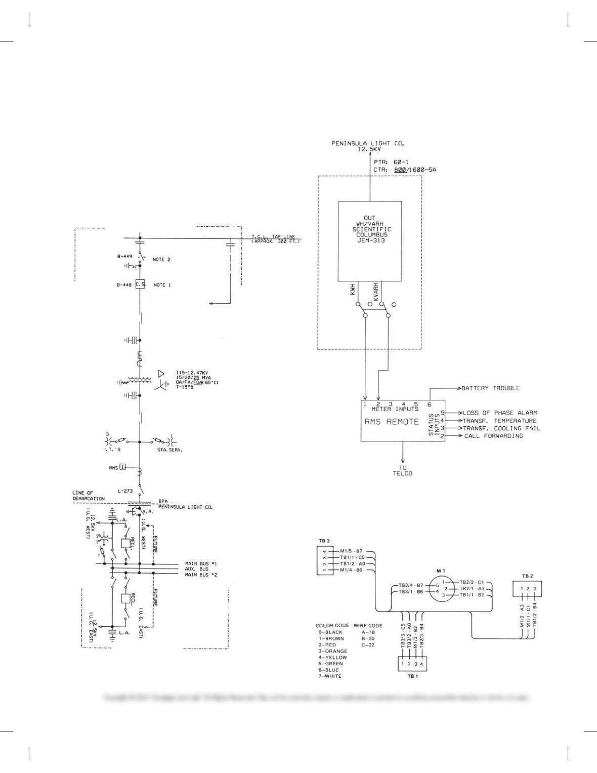
PROBLEM 20.7 Block diagram
Given the following engineering layout of the Potlatch-Pearl Sub-
station, draw the block diagram on an 11 3 17 sheet with an
architectural-style border and title block unless otherwise speci-
fied by your instructor. Sheets with borders and title blocks are
found as templates on the CD provided with this textbook. There
is no scale. The layout should neatly fill the sheet without crowd-
ing symbols or notes. Make all connection points Ø3/32 in. Pro-
vide the general note INTERPRET PER ANSI Y32.2.
Courtesy Bonneville Power Administration.
PROBLEM 20.8 Elementary diagram
Metering System.
Courtesy Bonneville Power Administration.
PROBLEM 20.9 Highway diagram
Draw all component outlines and feeder lines .020 in. (0.5mm)
wide and trunk lines .039 in. (1.00 mm) wide.
59728_ch20_EOC_ptg01.indd 5 22/02/16 10:50 am
6
PROBLEM 20.10 Wireless diagram
ELECTRICAL DIAGRAMS
Part 2: Problems 20.11 Through 20.15
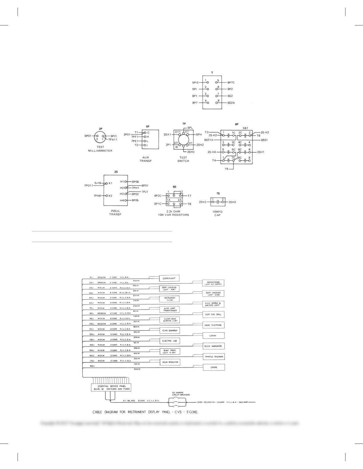
PROBLEM 20.11 Cable diagram
Display Panel-CVS-3 COND. Make all panel outlines and feeder
lines .020 in. (0.5 mm) wide and all trunk lines 0.39 in. (1.00 mm)
wide. Do all lettering .125 in. (3 mm) high, with component labels
.188 in. (5 mm) high and titles .25 (6 mm) high.
59728_ch20_EOC_ptg01.indd 6 22/02/16 10:50 am
7
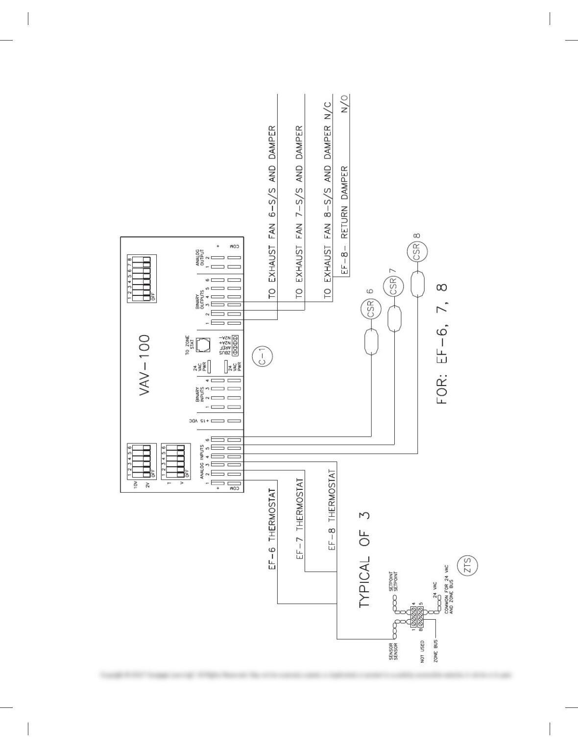
PROBLEM 20.12 Wiring diagram
59728_ch20_EOC_ptg01.indd 7 22/02/16 10:50 am
8
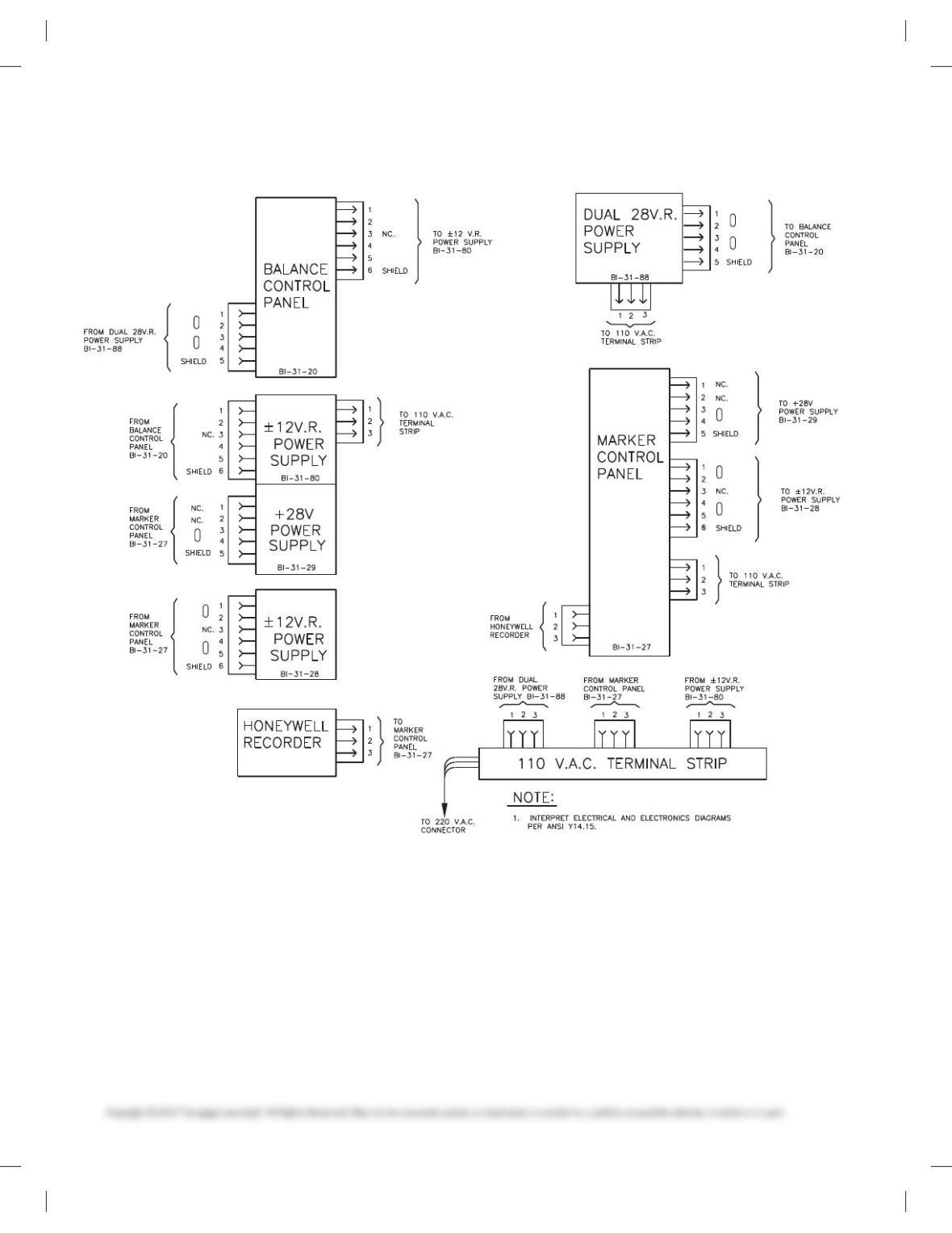
PROBLEM 20.13 Wireless diagram
59728_ch20_EOC_ptg01.indd 8 22/02/16 10:50 am
9
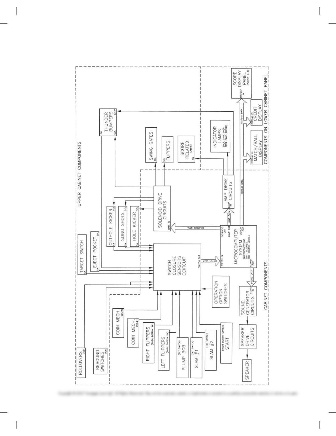
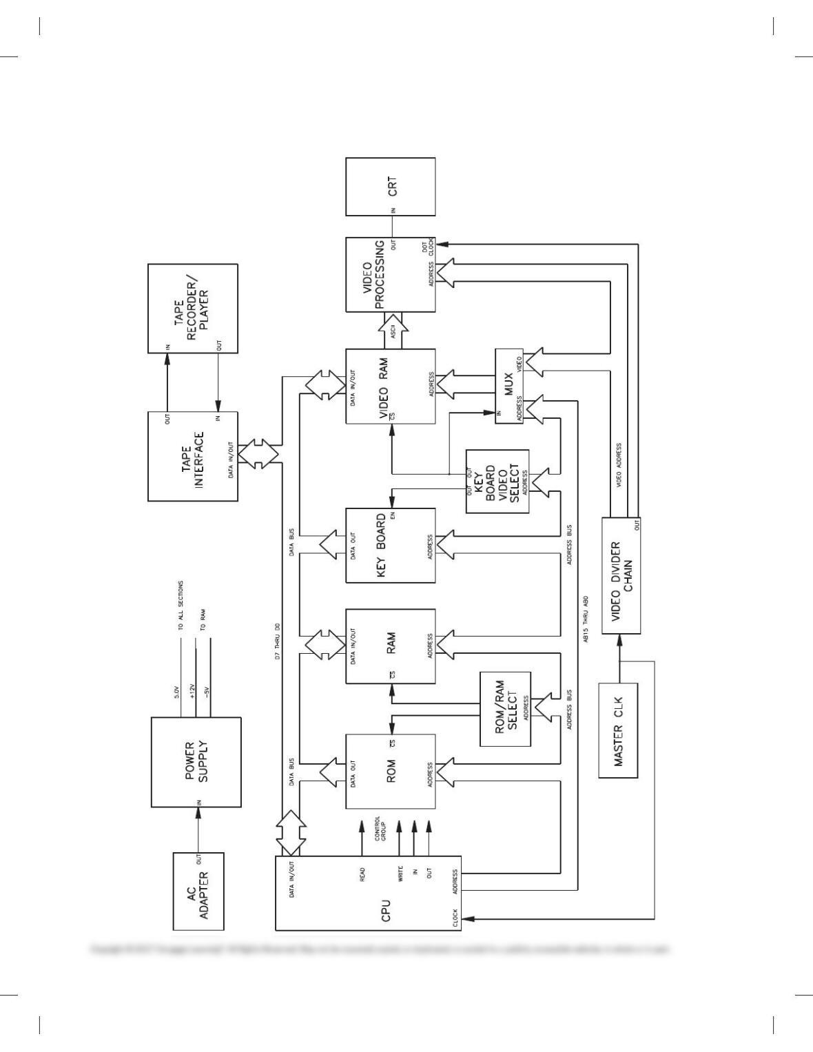
PROBLEM 20.14 Block diagram
59728_ch20_EOC_ptg01.indd 9 22/02/16 10:50 am
10
PROBLEM 20.15 Block diagram
59728_ch20_EOC_ptg01.indd 10 22/02/16 10:50 am
11
ELECTRICAL DRAWINGS
Part 3: Problems 20.16 Through 20.34
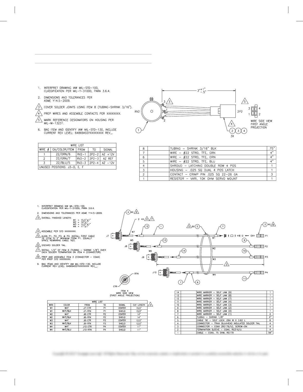
PROBLEM 20.16 Wiring harness
Courtesy Flir Systems, Inc.
PROBLEM 20.17 Wiring harness
Courtesy Flir Systems, Inc.
59728_ch20_EOC_ptg01.indd 11 22/02/16 10:50 am
12
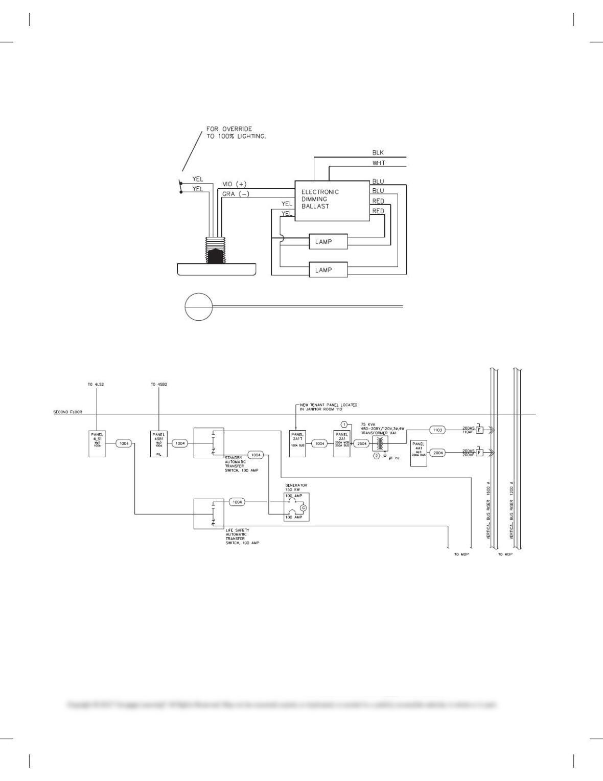
PROBLEM 20.18 Photocell wiring diagram
PHOTOCELL WIRING DIAGRAM
NO SCALE
2
E1
PROBLEM 20.19 Block diagram
PROBLEM 20.20 Cable assembly
Given the cable assembly engineering layout in Figure 20.12,
page 674, do the following:
1. Draw the cable assembly, wiring diagram, and bill of
materials.
2. Approximate dimensions that are not given.
3. Use an appropriate sheet size of your choice and an ASME
style border and title block. Sheets with borders and title
blocks are found as templates on the CD provided with this
textbook.
4. Use ASME standard line widths for cable assembly and 0.5
mm lines for wiring diagram.
5. Use .12 in. (3 mm) lettering with .24 in. (6 mm) high letters in
balloons and titles.
6. Make balloons Ø 1/2 in. (25 mm).
7. Letter the following general notes:
59728_ch20_EOC_ptg01.indd 12 22/02/16 10:50 am
13
1. DIMENSIONS AND TOLERANCES PER ASME Y14.5-2009.
2. INTERPRET DRAWING PER IEEE 315A.
3. DIMENSIONS ARE IN INCHES WITH TOLERANCES: FRAC-
TIONS 5 61/64, 5 6.XX .010, .XXX 5 6.005.
4. 32 MICRO IN FINISH ON METAL PARTS.
5. MATERIAL BRONZE.
6. USE SPEC 6712 FOR WIRE END PREPARATION.
PROBLEM 20.21 Bus layout plan view
Given the engineering layout shown in Figure 20.16, page 679, for
the Narrows substation, draw the bus layout using a 3/160 5 19-00
(1:50 metric) scale. Use an architectural-style border and title
block. The following line widths are recommended:
.014 in. (0.35 mm) Extension, dimension, balloon lines,
all connections
.020 in. (0.50 mm) Component and bus lines and
lettering
.024 in. (0.60 mm) Titles
Draw balloons Ø 9/32 in. (7–8 mm). Draw north arrow S458 W.
Draw bus lines from given dimensions and fill in solid except for
connections. Estimate dimensions not given.
PROBLEM 20.22 Bus elevations
Given the partial engineering layout shown in Figure 20.17,
page 679, for the Narrows substation, draw the bus elevation.
Follow all other instructions given in Problem 20.21.
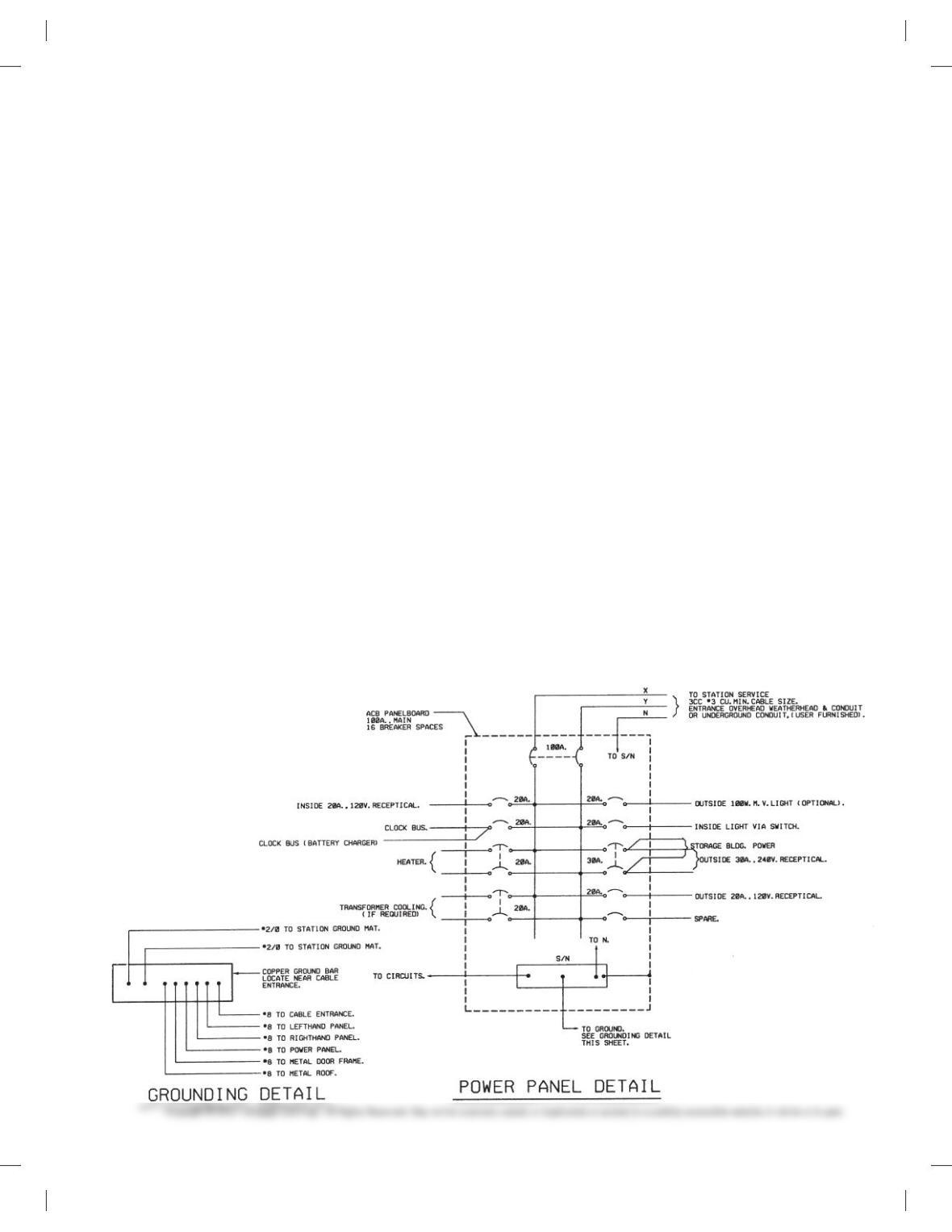
PROBLEM 20.23 Grounding layout
Given the partial engineering layout shown in Figure 20.19,
page 680, of the Narrows substation, draw the grounding layout
at a scale of 10 = 109-00 (1:100 metric). Include notes and ground-
ing table. Follow all other instructions given in Problem 20.21.
PROBLEM 20.24 Grounding details
Given the partial engineering layout shown in Figure 20.20,
page 681, of the Narrows substation, draw the grounding detail.
Follow all other instructions given in Problem 20.21.
PROBLEM 20.25 Conduit installation layout
Given the partial engineering layout shown in Figure20.21,
page 682, of the Narrows substation, draw the conduit instal-
lation layout. A magnifying glass may be needed to read the
engineering layout. Follow all other instructions given in
Problem 20.21.
PROBLEM 20.26 Conduit installation details
Given the partial engineering layout of the conduit installation
detail shown in Figure 20.22, page 683, for the Narrows substa-
tion, draw the given views. Follow all other instructions given in
Problem 20.21.
PROBLEM 20.27 Residential electrical
Given the typical electrical layouts shown in Figures 20.29,
page 685 and 20.30, page 686, draw each one at a scale of 1/40 5
19-00 (1:50 metric). Place one next to the other. Estimate dimen-
sions making your drawing about twice the size of the given
drawing. Use an architectural-style border and title block.
PROBLEM 20.28 Power panel detail
Narrows substation.
Courtesy Bonneville Power Administration
59728_ch20_EOC_ptg01.indd 13 22/02/16 10:50 am

14
PROBLEM 20.29 Electrical floor plan
Given the partial engineering upper-floor power layout shown in
Figure 20.34, page 686, draw the plan using a 1/40 5 19-00 (1:50
metric) scale. Estimate dimensions, making your drawing about
three times the size of the given drawing. Use an architectural-
style border and title block.
PROBLEM 20.30 Reflected ceiling plan
Given the engineering layout shown in Figure 20.35, page 686,
draw the reflected ceiling plan at a 1/40 5 19-00 (1:50 metric)
scale. Estimate unknown dimensions. Use an architectural-style
border and title block.
PROBLEM 20.31 Roof plan—electrical
Given the partial engineering layout shown in Figure 20.36,
page 687, draw the roof plan—electrical at a 1/40 5 19-00
(1:50 metric) scale. Estimate unknown dimensions. Use an archi-
tectural-style border and title block.
PROBLEM 20.32 Commercial schematic wiring diagram
Given the engineering layout shown in Figure 20.37, page 687,
draw the beverage cooler condenser unit wiring diagram.
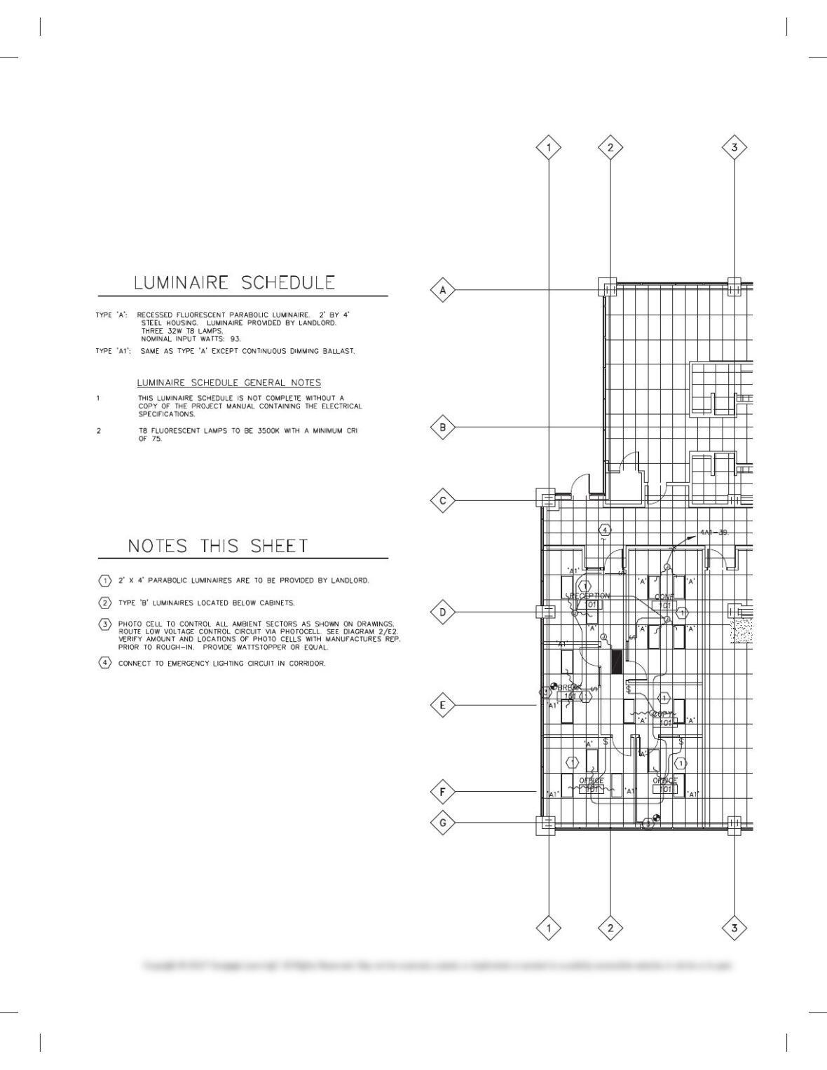
PROBLEM 20.33 First-floor lighting plan
Use the problem layout on the following page to create the
partial lighting plan shown. Use a 1/40 5 19-00 (1:50 metric)
scale to draw the floor plan. Make the dimensions to your own
specifications but proportional to the given engineering
drawing. Use appropriate CADD layers. Use an architectural-
style border and title block.
Courtesy Interface Engineering
59728_ch20_EOC_ptg01.indd 14 22/02/16 10:50 am
15
59728_ch20_EOC_ptg01.indd 15 22/02/16 10:50 am
16
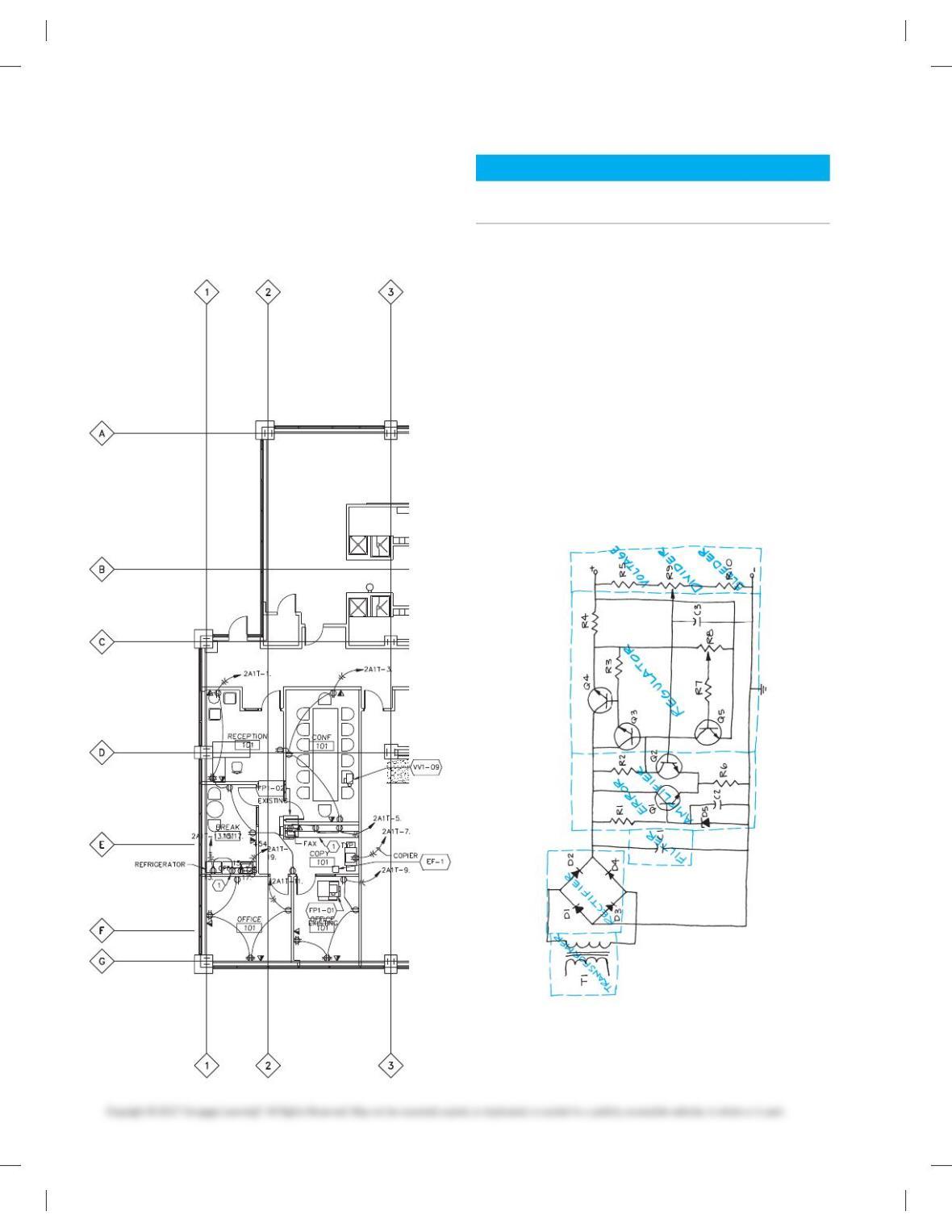
PROBLEM 20.34 First-floor power plan
Use the partial floor plan that you drew in Problem 20.33 as a
guide to create the partial power plan shown in the following
engineering drawing. Use appropriate CADD layers. Use an
architectural-style border and title block.
Courtesy Interface Engineering
BLOCK AND SCHEMATIC DIAGRAMS
Part 4: Problems 20.35 Through 20.45
1. Follow previous instructions unless otherwise specified.
2. Use an appropriate sheet size of your choice and an
ASME-style border and title block.
3. Use the selected engineering layouts and sketches to pre-
pare each drawing. Keep in mind that engineering
sketches can contain slight errors in format and symbol
accuracy. Verify proper representation before drawing
each symbol.
PROBLEM 20.35 Block diagram
Given the schematic diagram sketch that has been divided
into stages, prepare a block diagram using 11 3 17 (A3metric)
size, unless otherwise specified by your instructor. Make
all lines .020 in. (0.5 mm) wide. Complete all lettering .12 in.
(3 mm) high with titles .24 in. (6 mm) high. The sketch does not
show connection dots.
59728_ch20_EOC_ptg01.indd 16 22/02/16 10:50 am
17
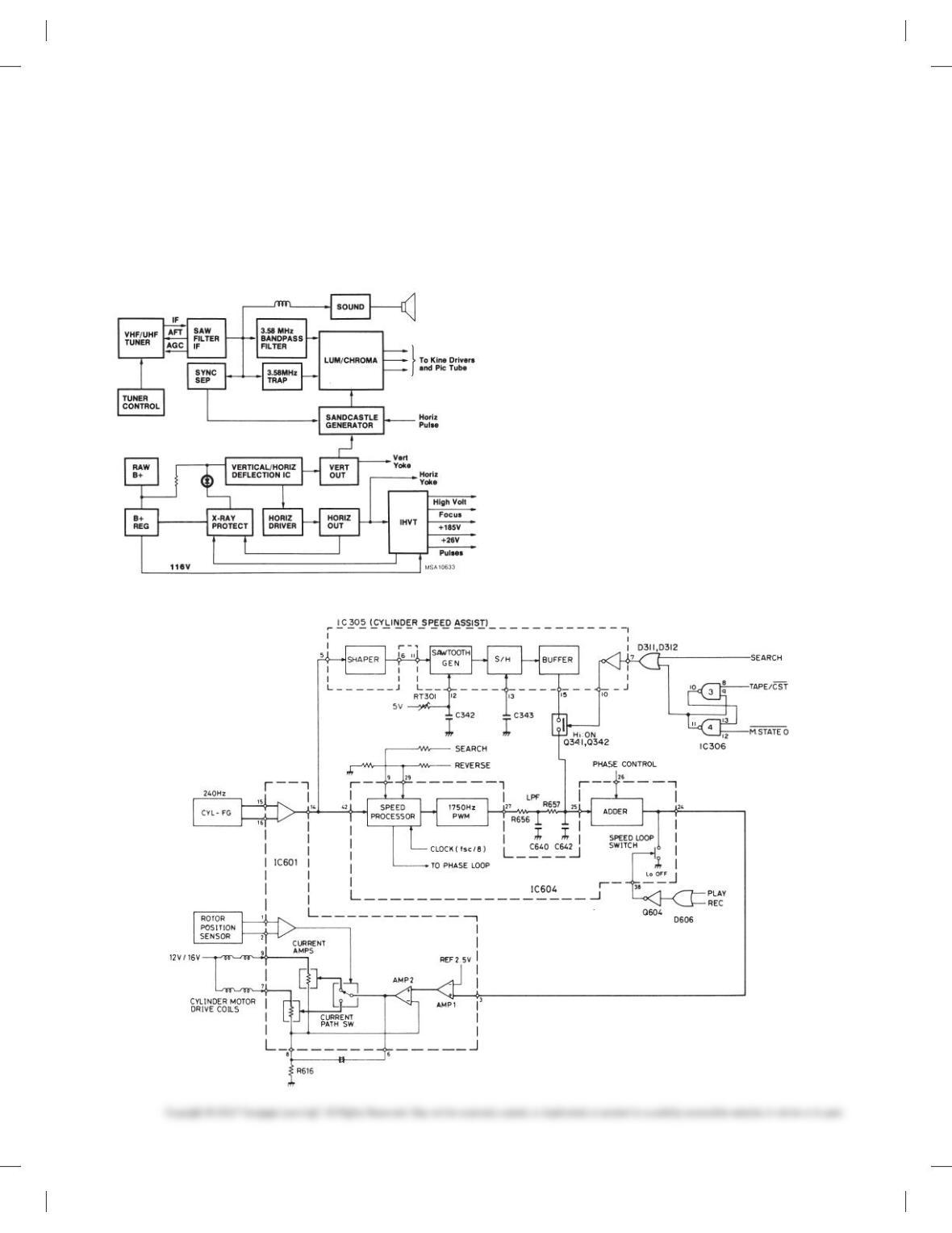
PROBLEM 20.36 Television receiver block diagram
Given the block diagram engineering layout, draw the block dia-
gram using 11 3 17 (A3 metric) size unless otherwise specified
by your instructor. Do all lettering .12in. (3 mm) high with titles
.24 in. (6 mm) high. Use .020 in. (0.5 mm) thick lines unless oth-
erwise specified on the engineering sketch.
Courtesy RCA Consumer Electronics
PROBLEM 20.37 Cylinder speed block diagram
Given the block diagram engineering layout, draw the block dia-
gram using 17 3 22 (A2 metric) size, unless otherwise specified
by your instructor. Do all lettering .12in. (3 mm) high with titles
.24 in. (6 mm) high. Use .020 in. (0.5 mm) thick lines unless oth-
erwise specified on the engineering sketch.
Courtesy RCA Consumer Electronics
PROBLEM 20.38 Schematic diagram
Given the schematic engineering sketch, make a schematic dia-
gram using 11 3 17 (A3 metric) size. There is no scale, and the
drawing must be balanced, uncluttered, and easy to read. Use the
following instructions unless otherwise specified by your
instructor:
1. Draw the entire schematic with .020 in. (0.5 mm) wide lines.
2. Do all lettering .12 in. (3 mm) high with titles .24 in. (6mm)
high.
3. Follow the left-to-right and top-to-bottom labeling system
using coding as described in this chapter: R1, R2, R3 . . . , C1,
C2. . . .
4. Label horizontal components above and vertical compo-
nents to the right.
59728_ch20_EOC_ptg01.indd 17 22/02/16 10:50 am
18
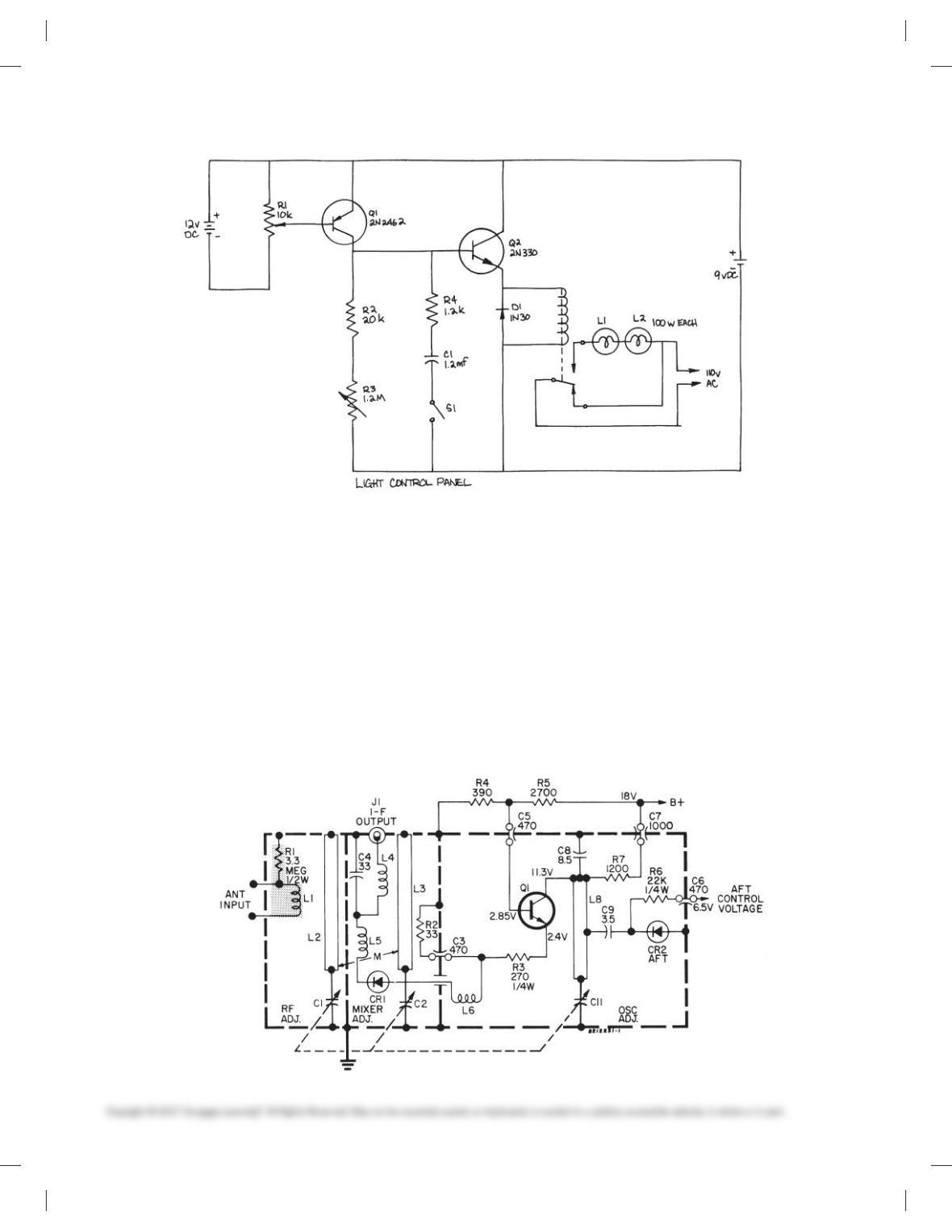
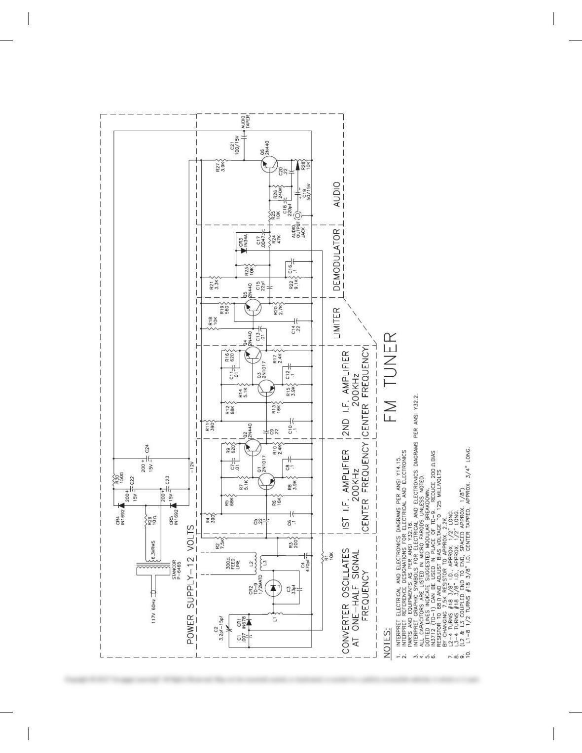
PROBLEM 20.39 Tuner schematic diagram
Given the schematic engineering layout, make a schematic dia-
gram using 11 3 17 (A3 metric) size. There is no scale, and the
drawing must be balanced, uncluttered, and easy to read. Use the
following instructions unless otherwise specified by your
instructor:
1. Draw the entire schematic with .020 in. (0.5 mm) wide lines
and dashed stage lines .028 in. (0.7 mm) wide.
2. Do all lettering .12 in. (3 mm) high with titles .24 in. (6mm) high.
3. Reference designators are not shown. Use the left-to-right and
top-to-bottom labeling system, using coding as described in
this chapter: R1, R2, R3 . . . , C1, C2. . . .
4. Label horizontal components above and vertical compo-
nents to the right.
5. Place connection dots as necessary.
Courtesy RCA Consumer Electronics
59728_ch20_EOC_ptg01.indd 18 22/02/16 10:50 am
19
PROBLEM 20.40 Television receiver tuner schematic diagram
Given the schematic engineering sketch, make a schematic dia-
gram using 17 3 22 (A2 metric) size. There is no scale, and the
drawing must be balanced, uncluttered, and easy to read. Use the
following instructions unless otherwise specified by your
instructor:
1. Draw the entire schematic with .020 in. (0.5 mm) wide lines
and dashed stage lines .028 in. (0.7 mm) wide.
2. Do all lettering .12 in. (3 mm) high with titles .24 in. (6mm)
high.
3. Reference designators are not shown; use the left-to-right
and top-to-bottom labeling system, using coding as de-
scribed in this chapter: R1, R2, R3 . . . , C1, C2. . . .
4. Label horizontal components above and vertical compo-
nents to the right.
5. Place connection dots as necessary.
PROBLEM 20.41 Electronics schematic
59728_ch20_EOC_ptg01.indd 19 22/02/16 10:50 am
20
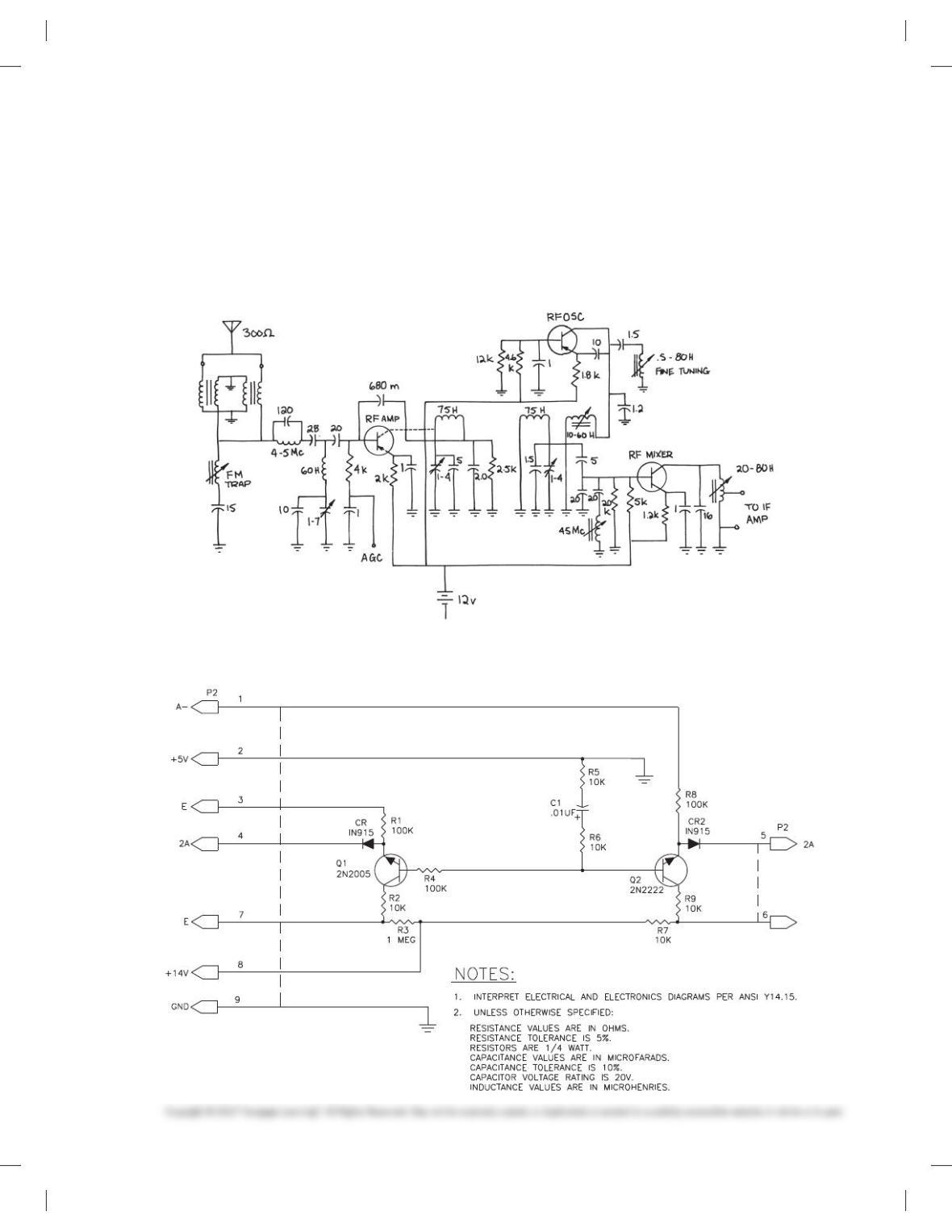
PROBLEM 20.42 FM tuner schematic
59728_ch20_EOC_ptg01.indd 20 22/02/16 10:50 am
21
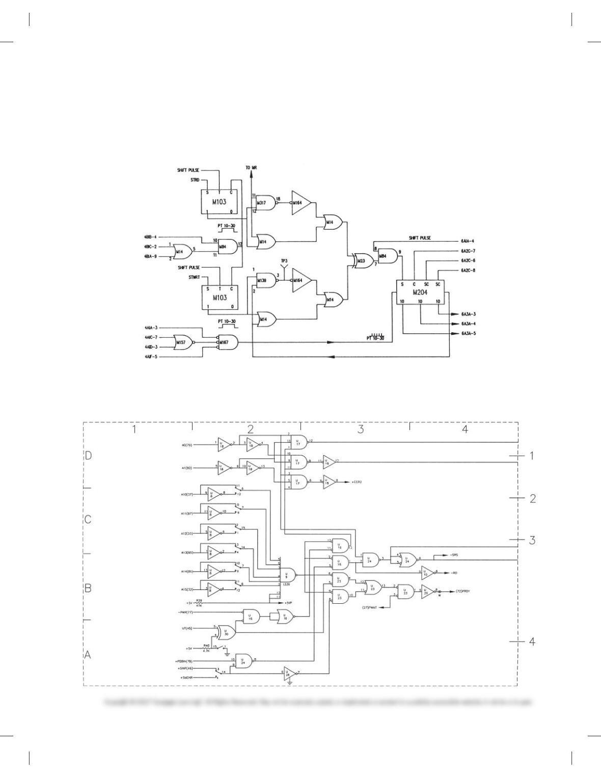
PROBLEM 20.43 Logic diagram
Given the IC schematic engineering layout for the logic dia-
gram, make a schematic drawing using 17 3 22 (A2metric)
size. Use the following instructions unless otherwise specified
by your instructor:
1. Do all line work and lettering using .020 in. (0.5 mm) width.
2. Do all lettering .12 in. (3 mm) high with titles .24 in. (6mm) high.
3. All connection points are Ø3/320 filled in.
4. Provide the general note INTERPRET PER IEEE 315A.
PROBLEM 20.44 Logic diagram
Given the schematic engineering sketch, make a schematic dia-
gram using 17 3 22 (A2 metric) size. There is no scale, and the
1. REFERENCE DESIGNATORS ARE
FOR REFERENCE ONLY AND MAY
NOT APPEAR ON PART.
2. RESISTOR VALUES ARE IN DHMS.
3. FOR PWB/COMPONENT ASSEMBLY,
SEE DWG. 100/01.
4. FOR PARTS, SEE SPL 100/02.
5. FOR PRINTED WIRING BOARD, SEE
DWG. 100/03.
NOTES:
drawing must be balanced, uncluttered, and easy to read. Use the
following instructions unless otherwise specified by your
instructor:
59728_ch20_EOC_ptg01.indd 21 22/02/16 10:50 am