PTER 2 DRAFTING EQUIPMENT,
MEDIA, AND REPRODUCTION
METHODS PROBLEMS
READING SCALES AND DRAFTING
MACHINE VERNIERS
Part 1: Problems 2.1 Through 2.9
Follow the instructions provided with each problem. Use a com-
puter to type your answers by giving the problem number, such
as Problem 2.1, with your answers for the following problems.
Print and submit the answers to your instructor, unless specified
otherwise. A civil engineer or mechanical engineer 1:1 (10) scale
is required to complete Problem 2.8. An architect 1/40 5 19–00
scale is required to complete Problem 2.9. Skip these problems if
the required scales are not available, unless otherwise specified
by your instructor.
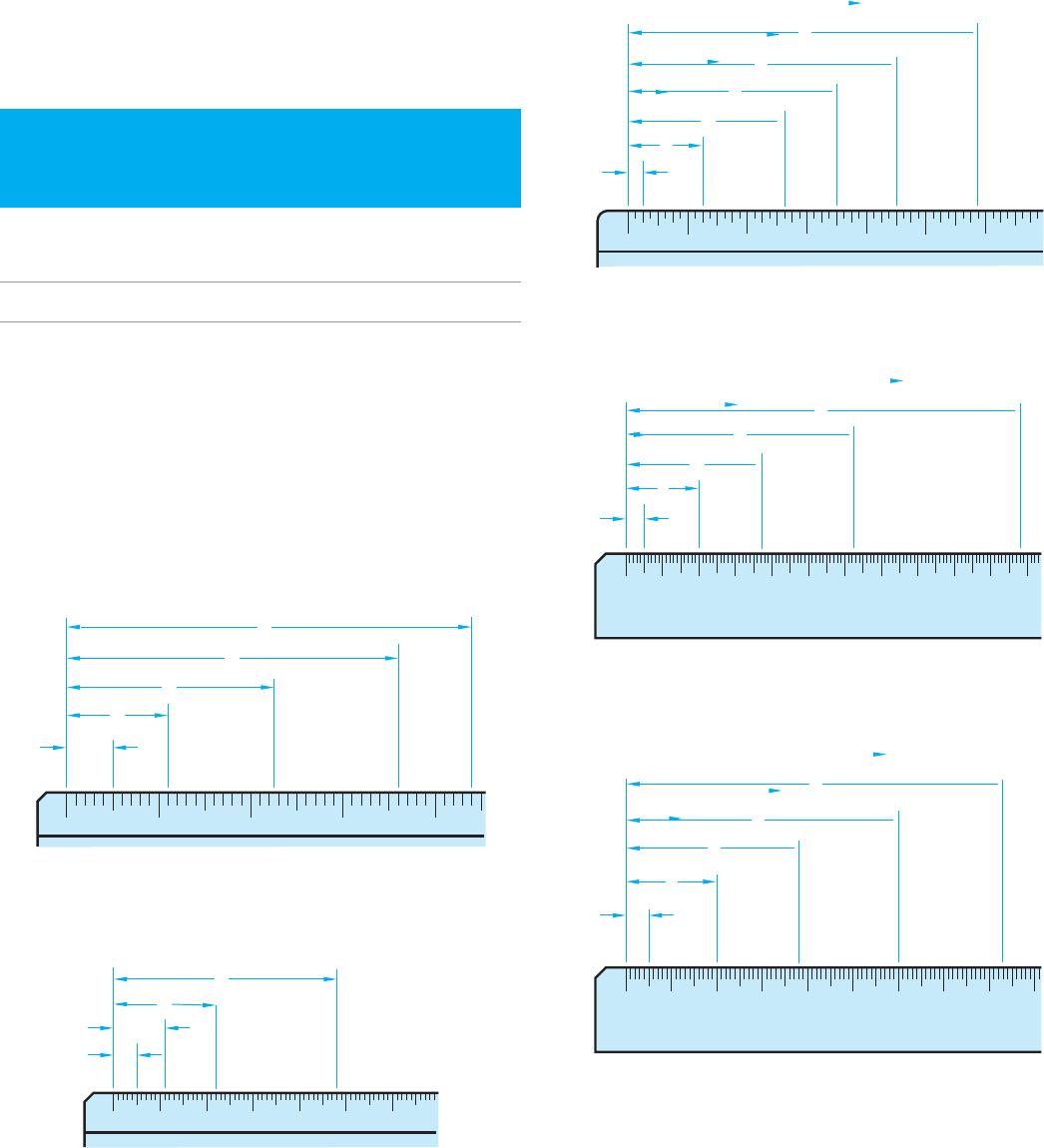
PROBLEM 2.1 Given the following civil engineer scale, de-
termine the readings at A, B, C, D, and E.
012
FULL SCALE = 1:1
34
10
E
A
B
C
D
PROBLEM 2.2 Given the following civil engineer scale, de-
termine the readings at A, B, C, and D.
012
HALF SCALE = 1:2
3456
20
A
C
B
D
PROBLEM 2.3 Given the following architect scale, deter-
mine the readings at A, B, C, D, E, and F.
123
FULL SCALE = 1:1
16
A
C
B
D
E
F
PROBLEM 2.4 Given the following metric scale, determine
the readings at A, B, C, D, and E.
0 102030405060708090100110
FULL SCALE = 1:1
1:1
A
C
B
D
E
PROBLEM 2.5 Given the following metric scale, determine
the readings at A, B, C, D, and E.
0 20 40 60 80 100 120 140 160
HALF SCALE = 1:2
1:2
A
B
C
D
E
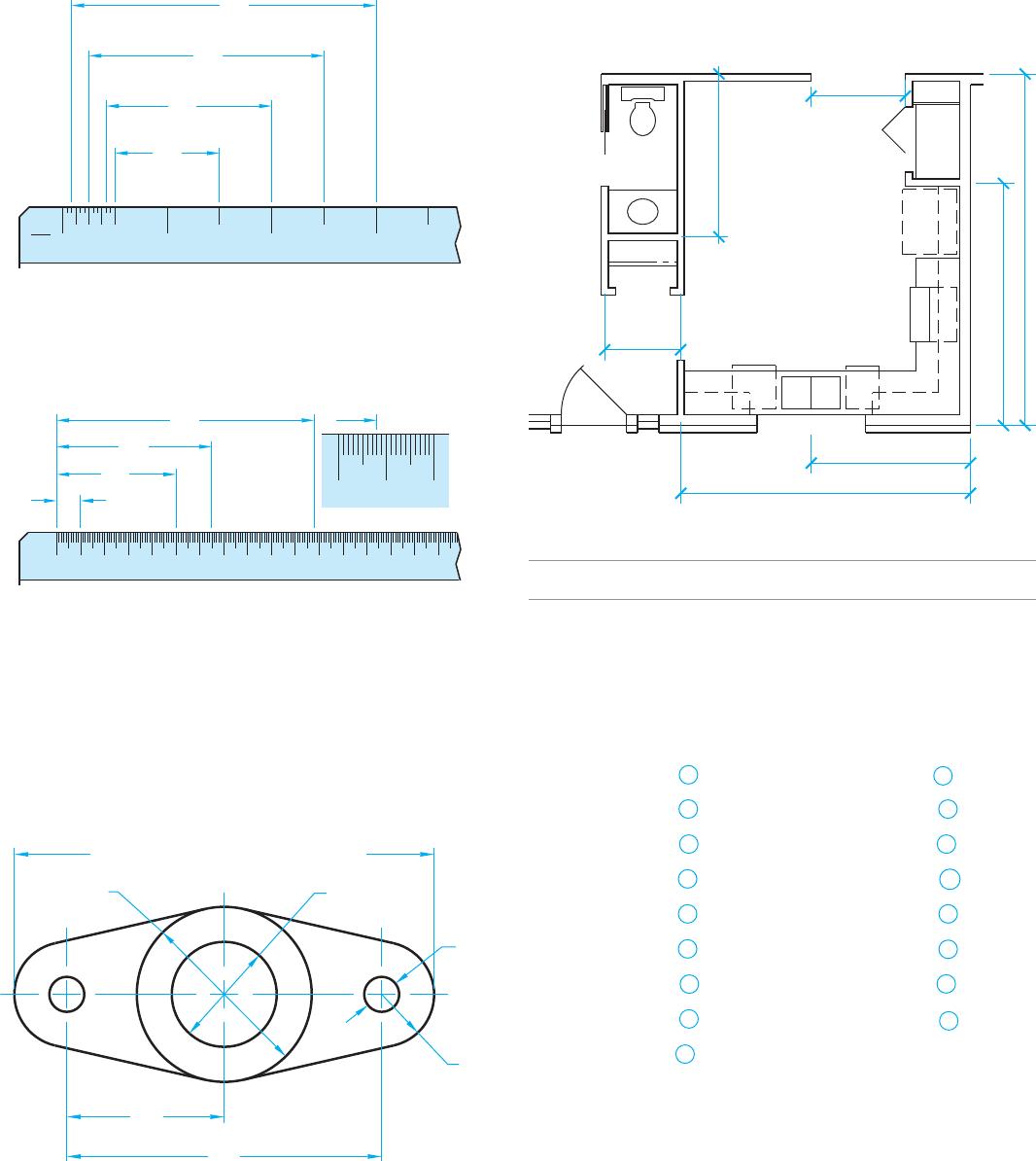
PROBLEM 2.6 Given the following architect scale, deter-
mine the readings at A, B, C, and D.
0
3
814 213 412 6
D
C
B
A
PROBLEM 2.7 Given the following mechanical engineer
scale, determine the readings at A, B, C, and D.
50 024 6 8 10121416
10 12
FULL SIZE; 1:1; 1″=1″
ENLARGED VIEW
D
C
B
A
PROBLEM 2.8 A civil engineer or mechanical engineer 1:1
(10) scale is required to complete this problem. Given the fol-
lowing mechanical drawing, use the civil engineer or mechani-
cal engineer 1:1 (10) scale to determine the dimensions at A, B,
C (to be calculated as shown), D, E, F, and G. Print the problem
page at 100% for use in making measurements.
G
B
C (Calculate C based on B and D)
A
E
D
F
PROBLEM 2.9 An architect 1/40 5 19–00 scale is required to
complete this problem. Given the following partial floor plan,
use the architect 1/40 5 19–00 scale to determine the dimen-
sions at A, B, C, D, E, F, and G. Print the problem page at 100%
for use in making measurements.
F
E
D
C
B
A
G
READING SHEET BLOCKS
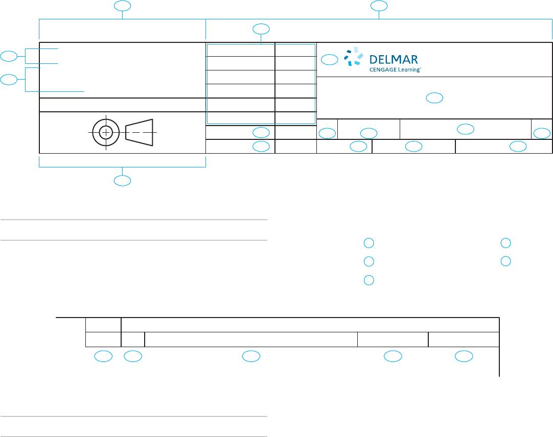
Part 2: Problems 2.10 Through 2.26
Given the following sheet blocks, with characteristics labeled A
through Q, name and completely identify each characteristic.
Use a computer to type your answers by giving the problem
number, such as Problem 2.10, with your answers for the follow-
ing problems. Print and submit the answers to your instructor,
unless otherwise specified by your instructor.
PROBLEM 2.10 A
PROBLEM 2.11 B
PROBLEM 2.12 C
PROBLEM 2.13 D
PROBLEM 2.14 E
PROBLEM 2.15 F
PROBLEM 2.16 G
PROBLEM 2.17 H
PROBLEM 2.18 I
PROBLEM 2.19 J
PROBLEM 2.20 K
PROBLEM 2.21 L
PROBLEM 2.22 M
PROBLEM 2.23 N
PROBLEM 2.24 O
PROBLEM 2.25 P
PROBLEM 2.26 Q
ENGINEER
APPROVALS
DRAFTER
CHECKER TITLE
CAGE CODE
SHEET
DATE
REV
SCALE
DWG NO.
SIZE
5 Maxwell Drive
Clifton Park, NY 12065-2919
D
E
F G I
H
LKJO
N
M
THIRD ANGLE PROJECTION
UNLESS OTHERWISE SPECIFIED
DIMENSIONS ARE IN INCHES (IN)
TOLERANCES: 1 PLACE ±.1 2 PLACE ±.01
3 PLACE ±.005 4 PLACE ±.0050 ANGLES
30′ FINISH 62 u IN
AC
B
Q
P
READING A REVISION HISTORY BLOCK
Part 3: Problems 2.27 Through 2.31
Given the following revision history block, with characteristics
labeled 1 through 5, name and completely identify each charac-
teristic. Use a computer to type your answers by giving the prob-
lem number, such as Problem 2.27, with your answers for the
following problems. Print and submit the answers to your in-
structor, unless specified otherwise.
PROBLEM 2.27 1
PROBLEM 2.28 2
PROBLEM 2.29 3
PROBLEM 2.30 4
PROBLEM 2.31 5
MATH PROBLEMS
Part 4: Problems 2.32 Through 2.41
Convert the following angle measurements to decimal degrees.
PROBLEM 2.32 159
PROBLEM 2.34 18859
PROBLEM 2.36 2138429
PROBLEM 2.33 78309
PROBLEM 2.35 2008189
Convert the following angle measurements to degrees and
minutes.
PROBLEM 2.37 60.48
PROBLEM 2.39 .278
PROBLEM 2.41 –45.18
PROBLEM 2.38 9.58
PROBLEM 2.40 177.88
2 3 4 5
ZONE REV DATE APPROVED
REVISION HISTORY
DESCRIPTION
1
2
Chapter 2
Drafting Equipment, Media, and Reproduction Methods
Solutions to End-of-Chapter Problems
Reading Scales and Drafting Machine Verniers
Part 1: Problems 2.1 Through 2.9
PROBLEM 2.1
A. .5
PROBLEM 2.2
PROBLEM 2.3
PROBLEM 2.4 Full Scale

PROBLEM 2.5 Half Scale
PROBLEM 2.6
PROBLEM 2.7
PROBLEM 2.8
PROBLEM 2.9
4
Reading Sheet Blocks
Part 2: Problems 2.10 Through 2.26
PROBLEM 2.10 (A)
Title Block
A title block provides a variety of information about a drawing. ASME standards
PROBLEM 2.11 (B)
Angle of Projection Block
The angle of projection block specifies how to interpret a drawing according to the
PROBLEM 2.12 (C)
Dimensioning and Tolerancing Block
The dimensioning and tolerancing block is used to specify the general dimensioning
PROBLEM 2.13 (D)
Company or Design Activity
Normally displays the name, address, and contact information of the company, or

5
PROBLEM 2.14 (E)
Title
Displays the title of the drawing, which is typically the product assembly name or
PROBLEM 2.15 (F)
Sheet Size
PROBLEM 2.16 (G)
CAGE Code
The CAGE code is a five-number code assigned by the U.S. Defense Logistic
Service Center (DLSC) to all Department of Defense contractors. CAGE stands for
PROBLEM 2.17 (H)
Drawing Number
Some companies specify the part or related number as the drawing number. Most
PROBLEM 2.18 (I)
Revision
Specifies the current revision of the part or drawing. A new or original drawing is—
6
PROBLEM 2.19 ( J)
Scale
Specifies the principal drawing scale, such as FULL or 1:1, HALF or 1:2, DBL or
PROBLEM 2.20 (K)
Weight
Indicates the actual or estimated weight of the part or assembly. Some companies
PROBLEM 2.21 (L)
Sheet
Identifies the sheet relative to a group of sheets or set of sheets. When multiple
PROBLEM 2.22 (M)
Approvals 1
The entire area above items N and 0 in the problem example typically allows for
approval names or signatures and dates by people directly involved with preparing
7
PROBLEM 2.23 (N)
Approval 2
Allows for approval by an individual, design activity, or organization not directly
related with preparing or approving the drawing, such as a subcontractor hired to
PROBLEM 2.24 (O)
Approval 3
Allows for approval by an individual, design activity, or organization not specified
in the other approval blocks. This block may be required when producing drawings
PROBLEM 2.25 (P)
The upper portion of the dimensioning and tolerancing block provides a note
indicating that all dimensions are in millimeters (mm) or inches (IN), unless
PROBLEM 2.26 (Q)
The dimensioning and tolerancing block compartment continues with information
8
Reading a Revision History Block
Part 3: Problems 2.27 Through 2.31
PROBLEM 2.27
Zone
This compartment is only used if the drawing includes zoning and specifies the
PROBLEM 2.28 (2)
Revision
Enter the revision letter or number, such as A, B, C, or D. Succeeding letters are to
PROBLEM 2.29 (3)
Description
PROBLEM 2.30 (4)
Date
Fill in the day, month, and year on which the engineering change is ready for
9
PROBLEM 2.31 (5)
Approval
Math Problem Solutions
Part 4: Problems 2.32 Through 2.41