
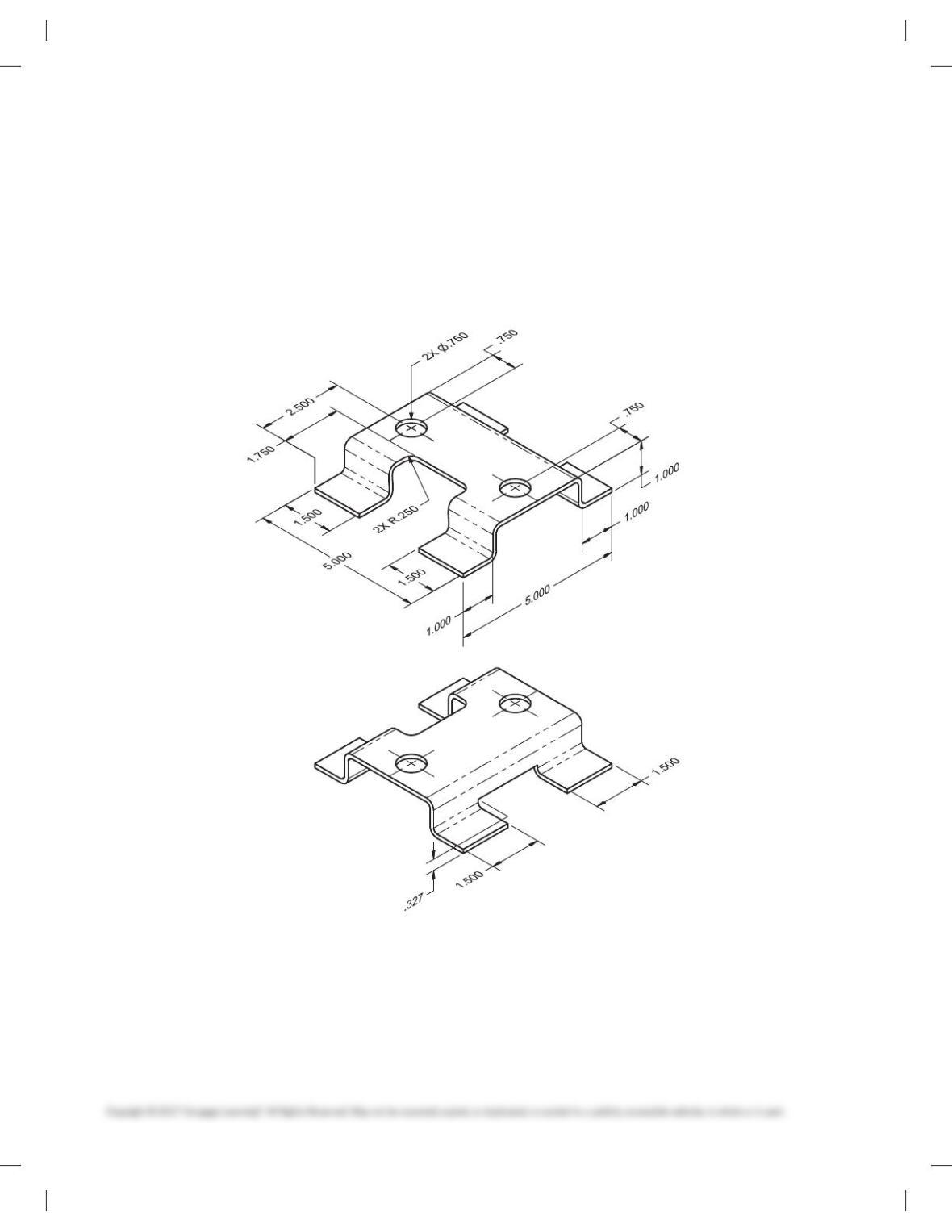
CHAPTER 19 PRECISION SHEET
METAL DRAFTING PROBLEMS
INSTRUCTIONS
1. From the given sketch, draw the required views.
2. Include all dimensions needed using the specified dimen-
sioning system and correct ASME dimensioning standards.
3. Use an appropriate sheet size, border, and ASME standard
sheet blocks.
4. Include the following general notes at the lower-left corner
of the sheet .5 in. each way from the corner border lines:
59728_ch19_EOC_ptg01.indd 1 03/02/16 10:35 am
NOTES:
1. DIMENSIONING AND TOLERANCING PER ASME Y14.5-2009.
2. REMOVE ALL BURRS AND SHARP EDGES.
Additional general notes can be required, depending on the
specifications of each individual assignment. Use the following
for tolerances for unspecified inch values. A tolerance block is
recommended as described in Chapter 2.
Unspecified Tolerances
Decimals In.
X6.1
XX 6.01
XXX 6.005
ANGULAR 6309
FINISH 125 µin.
For metric drawings, provide a general note that states TOLER-
ANCES FOR UNSPECIFIED DIMENSIONS COMPLY WITH ISO
2768-m. Provide a general note that states SURFACE FINISH
3.2 µm UNLESS OTHERWISE SPECIFIED.
(00.000)
(00.000)
(.812)
(5.812)
(6.625)
(1.875)
(3.500)
(5.125) (UP 908 @ .250 R)
(UP 908 @ .250 R)
(7.000)
2X Ø(.406)
FLAT PATTERN
(SCALE .50X)
SIDE OF
TANK REF
2X Ø
.416
.396
2X .281
.218
Ø .030 A
A
B
C
BCR
6.656
6.593
5.000
3.531
3.468
.843
.812
1.750
2.031
1.968
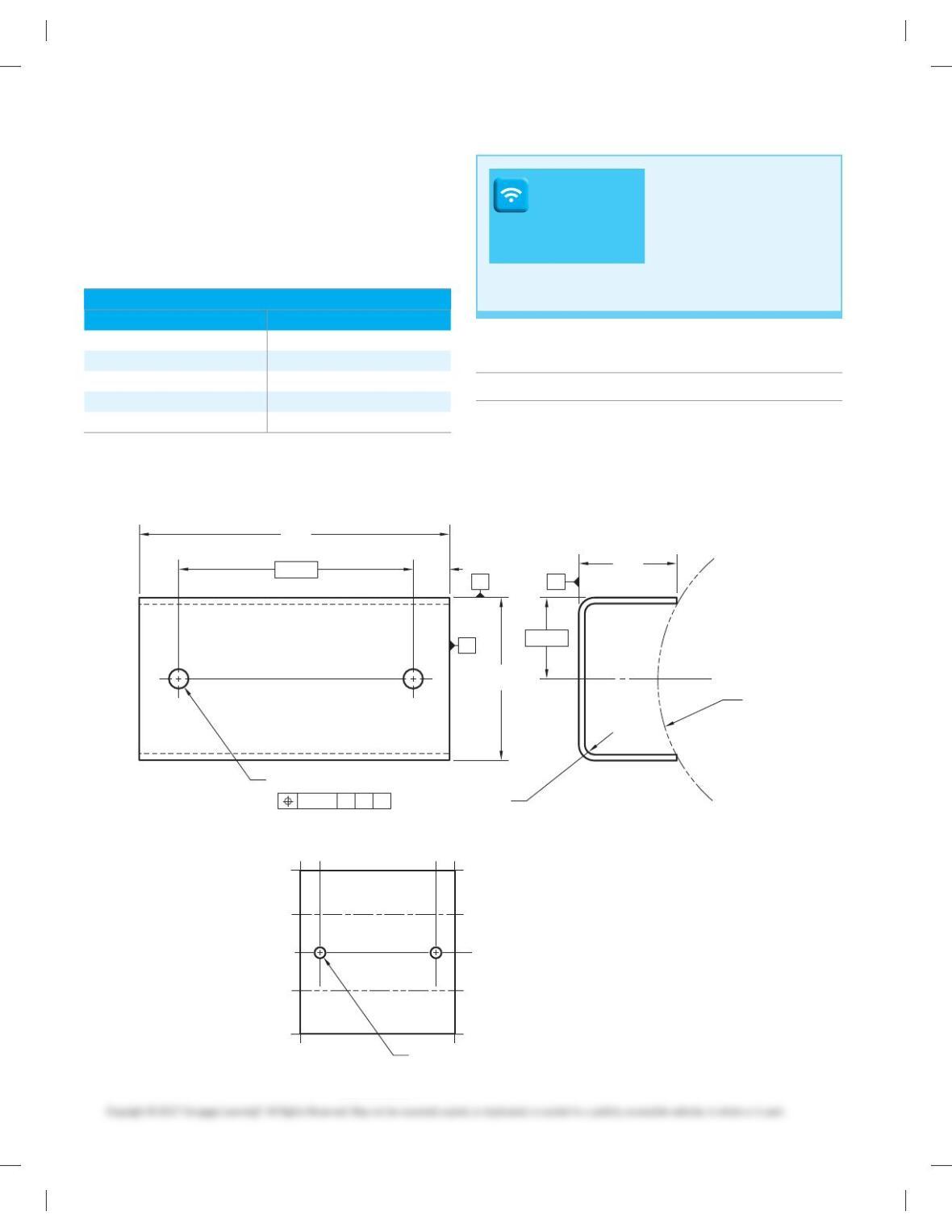
PRECISION SHEET METAL DETAIL
DRAWINGS
Part 1: Problems 19.1 Through 19.12
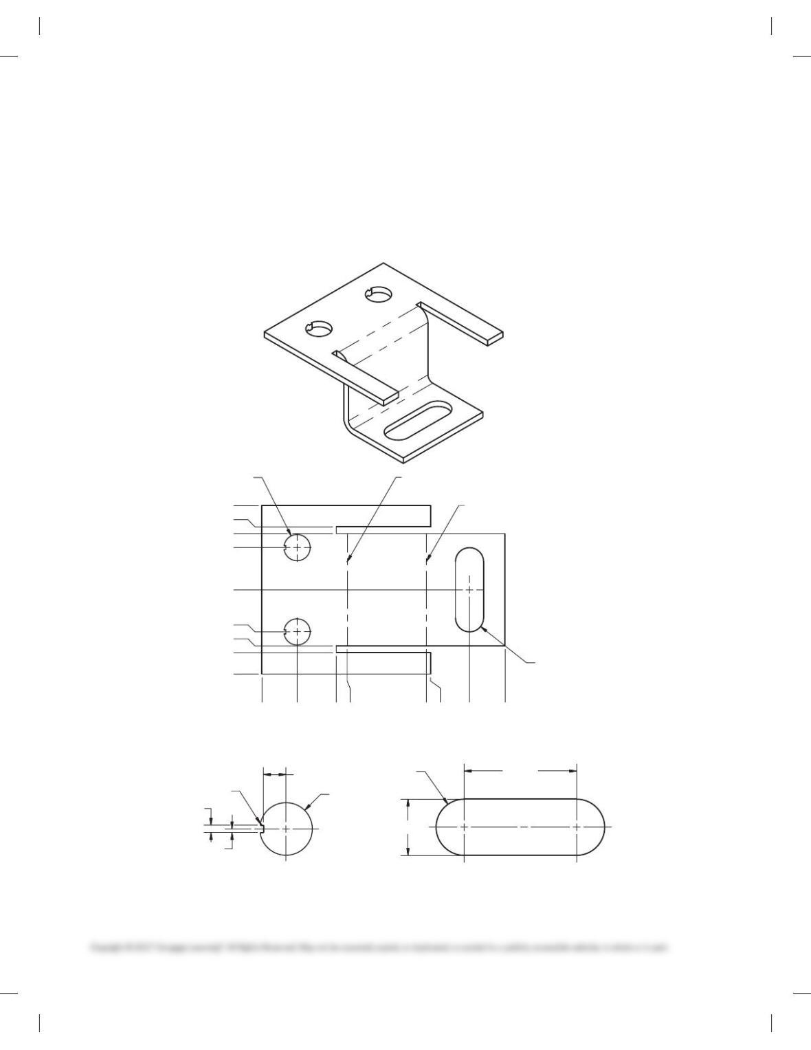
PROBLEM 19.1 Drawing displayed in form view and flat
pattern (in.)
Part Name: Mounting Bracket
Material: .23 THK 5086-H32
Courtesy TEMCO
DRAFTING
TEMPLATES
To access CADD template
files with predefined drafting
settings, go to the Student
Companion Website, select
Student Downloads and
Drafting Templates, and then
select the appropriate
template file.
59728_ch19_EOC_ptg01.indd 2 03/02/16 10:35 am
(00.000)
(00.000)
(.437)
(1.062)
(1.500)
(1.000)
(1.125)
(1.750)
(2.750)
1.062
.437
.625
1.250
.031
[
1.781
1.718
1.031
.968
2X .312
.250
[
2X (.281)
[
1.531
1.468
UP 908 @ SHARP R
B
A
AB
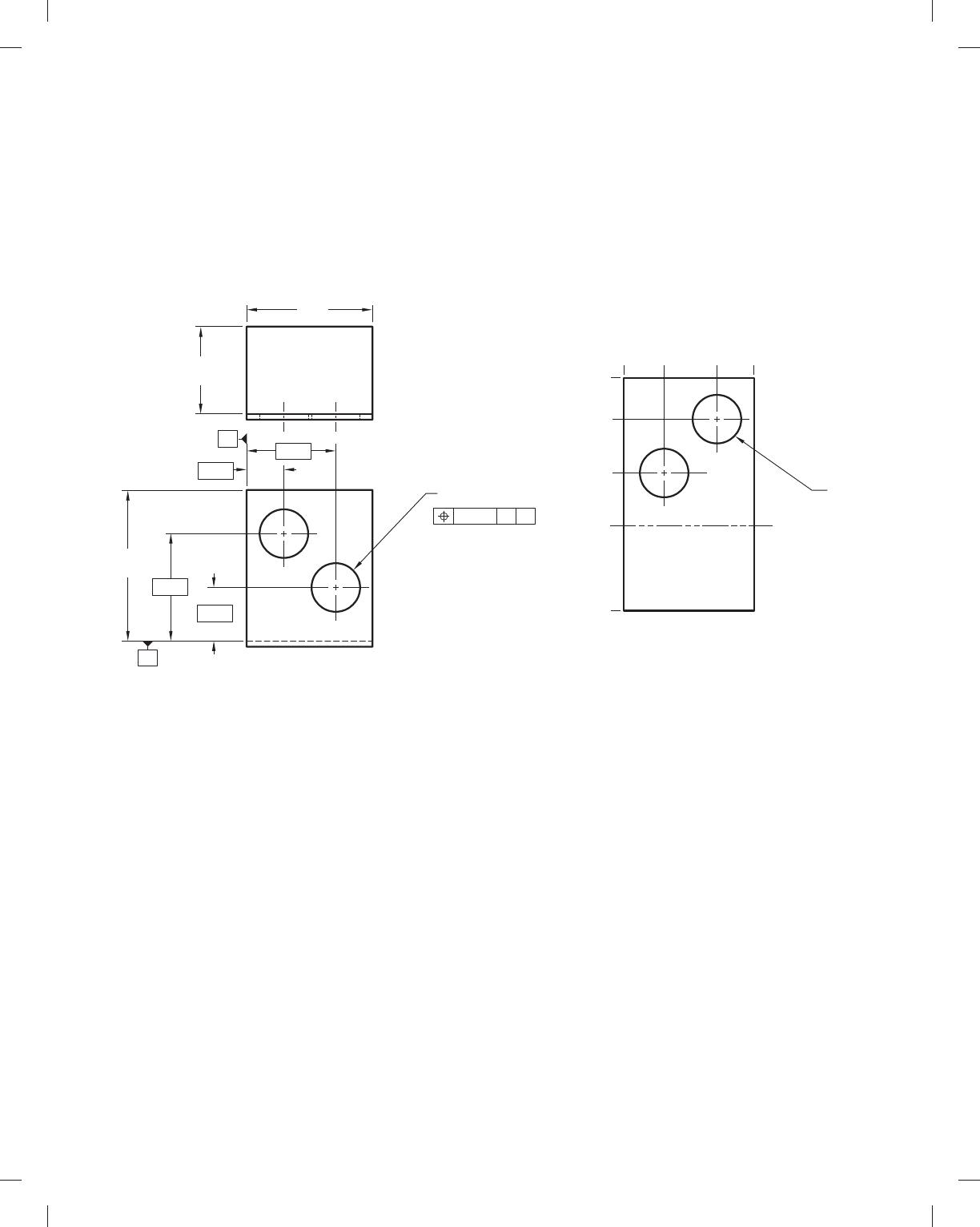
PROBLEM 19.2 Drawing displayed in form view and flat
pattern (in.)
Part Name: Bracket
Material: 14 GA GALV CRS
Courtesy TEMCO
59728_ch19_EOC_ptg01.indd 3 03/02/16 10:35 am
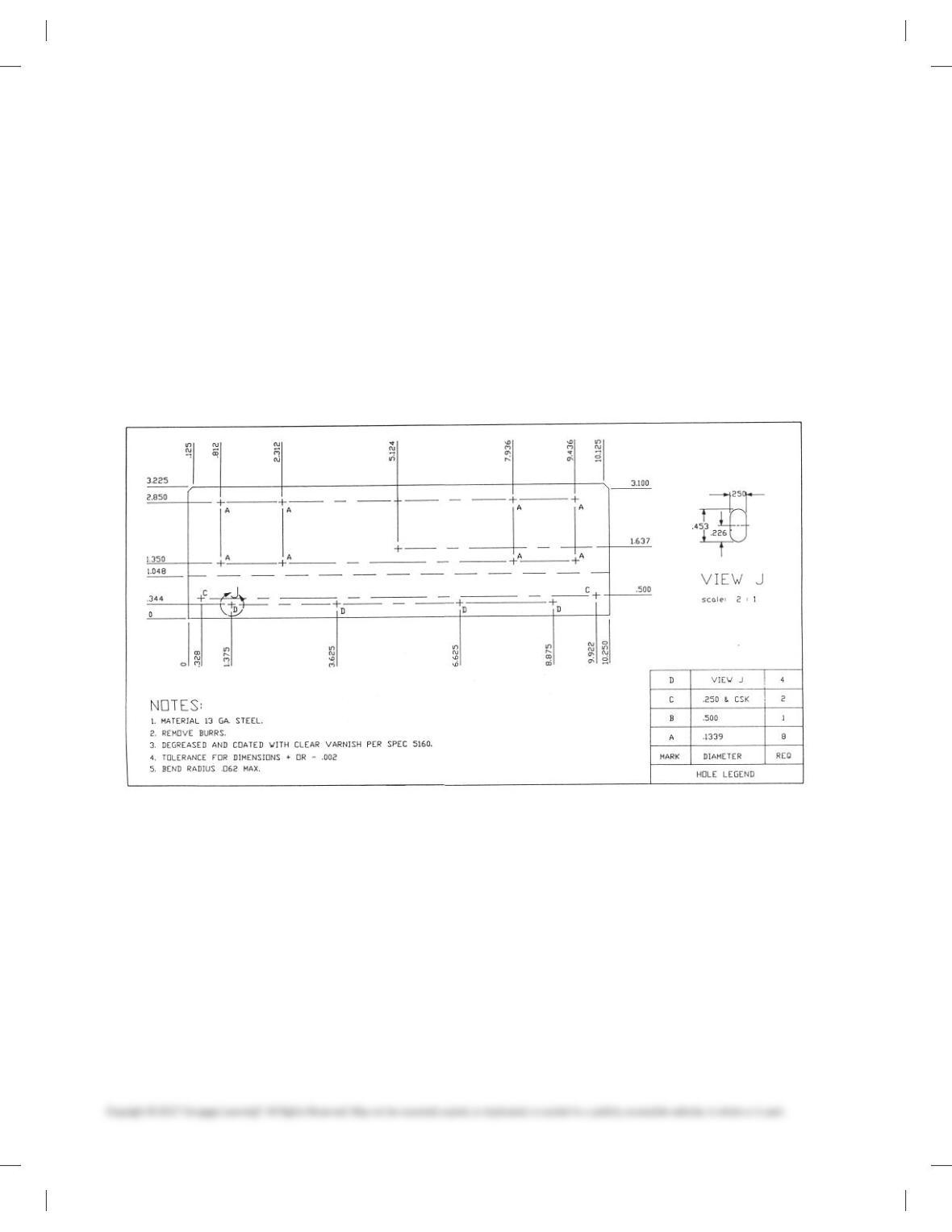
PROBLEM 19.3 Chassis layout (in.)
Part Name: Chassis
Material: Aluminum
Given: The engineer’s rough sketch of a computer component
chassis.
Do the following using correct ASME standards:
1. Make a flat pattern drawing of the given chassis on properly
sized sheet. Full scale is recommended.
2. Use arrowless tabular dimensioning from the given
datums.
59728_ch19_EOC_ptg01.indd 4 03/02/16 10:35 am
000
000
.250
.250
1.750
2.00
5.031
8.00
10.125
AA
C
D
C
000
.500
.625
5.875
.125 THK
10.250
000
.500
3.125
7. 1 2 5
8.750
10.625
12.625
14.000
2.50
4.875
6.500
7. 1 2 5
3.25
4.375
2X R
.250 .500
.125
.250
DETAIL D
BEND RADIUS = .062
AA
AAA
ABB
908
PROBLEM 19.4 Chassis layout
Given: The engineer’s rough sketch of a computer component
chassis.
Do the following:
1. Make a flat pattern drawing of the given chassis on a properly
sized sheet. Full scale is recommended. Establish the flat
pattern layout dimension by bend allowance calculations.
Show all math formulas and calculations on another paper.
2. Use arrowless tabular dimensioning from the given datums.
Dimensioning Table
Hole Symbol Hole Diameter Depth Quantity
A .123 Through 9
B .230 Through 2
C .469 .030 2
D See detail D Through 1
3. Standard dimensioning is needed for the total length of flat
pattern and a dimension from one datum to the bend line in
the flat pattern.
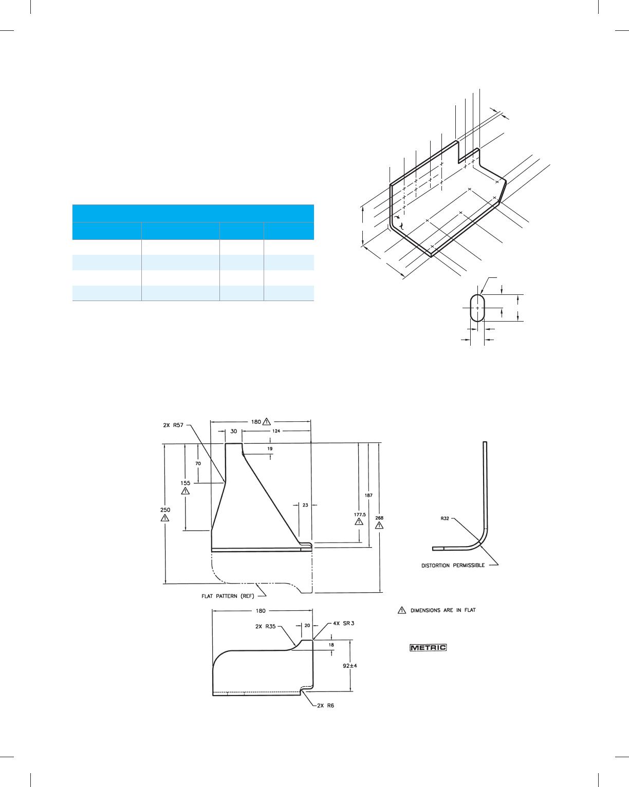
PROBLEM 19.5 Display of part in form view with flat pat-
tern shown as phantom line (in.)
Part Name: Formed Plate
Material: HC-112 6 mm THK
Problem based on original art courtesy Hyster Company.
59728_ch19_EOC_ptg01.indd 5 03/02/16 10:35 am
PROBLEM 19.6 Display of part in form view and in flat
pattern (in.)
Given the following engineer’s layout, draw the flat pattern and
the formed view. Use geometric dimensioning and tolerancing as
shown.
Part Name: Mounting Bracket
Material: 11 GA A569
Courtesy TEMCO
FLAT PATTERN
FORM VIEW
(3.546)
1. 12 5
.562
1.663
2X
(1.882)
2X (2.015)
2.250
(5.211)
2X R .281
.218
R
2X
.125
.075
2X .448
.436
.572
.562
¥
2X R .218
.156
10X R
.156
.093
2X (1.812)
9.031
8.968
1.281
1.218
UP 908
@ .187R
UP 908 @
.187R
2X R 8.876
8.814
1.656
2.031
1.968
3.593
3.531
7. 1 2 5
7.062
X
59728_ch19_EOC_ptg01.indd 6 03/02/16 10:35 am
1.891
3.783
2.641
5.283
R.5004X Ø1.0152X
Ø.280
.750
1.500
DOWN 180° R.525
CLB
SEE FOLDED VIEW
(R.525)BEND
(1.050)
PROBLEM 19.7 Display of 3-D part model, part in form view
and with flat pattern (in.)
Part Name: U-Strap
Material: 14 GA ASTM A366
Draw the 3-D model, formed views, and flat pattern using
unidirectional dimensioning.
59728_ch19_EOC_ptg01.indd 7 03/02/16 10:35 am
PROBLEM 19.8 Flat pattern (in.)
Part Name: Bracket
Material: 11-gauge (.1196 in.) SAE 1040 steel
The bend radius is equal to the thickness of the material.
Draw the flat pattern using unidirectional dimensioning.
59728_ch19_EOC_ptg01.indd 8 03/02/16 10:35 am
PROBLEM 19.9 3-D model, flat pattern, and punch ID (in.)
Part Name: Mounting Stand
Material: 11-gauge (.1196 in.) ASTM 525
Draw the 3-D model and the flat pattern using rectangular
coordinate dimensioning without dimension lines. Use the
punch identification and draw the punch details.
DETAIL PUNCH A
SCALE 2 / 1
A
DOWN 90° R.120
DOWN 90° R.120
DOWN 90° R.120
4X PID A
DOWN 90° R.120
.000
1.896
.100
2.896
8.896
11.692
11.792
13.688
.000
1.896
.100
1.896
5.896
7.692
7.792
9.688
1.000
3X R
1.000
1.000
2.000
59728_ch19_EOC_ptg01.indd 9 03/02/16 10:35 am
PROBLEM 19.10 3-D model, flat pattern, and punch ID (in.)
Part Name: Support Bracket
Material: 11-gauge (.1196 in.) ASTM 304
Draw the 3-D model and the flat pattern using rectangular
coordinate dimensioning without dimension lines. Use the
punch identification and draw the punch details.
.000
.380
.500
.750
1.500
2.250
2.500
2.620
3.000
.000
.625
1.321
1.516
2.927
3.000
3.693
4.323
2X PID 67495B
PID 67654A
CLB
BDN 90° X R.120
CLB
BUP 90° X R.120
.0650
.0325
Ø.4680
R.00704X
.2000
PUNCH 67495B
SCALE 2:1
2X R
.5000
1.0000
PUNCH 67654A
SCALE 2:1
59728_ch19_EOC_ptg01.indd 10 03/02/16 10:35 am
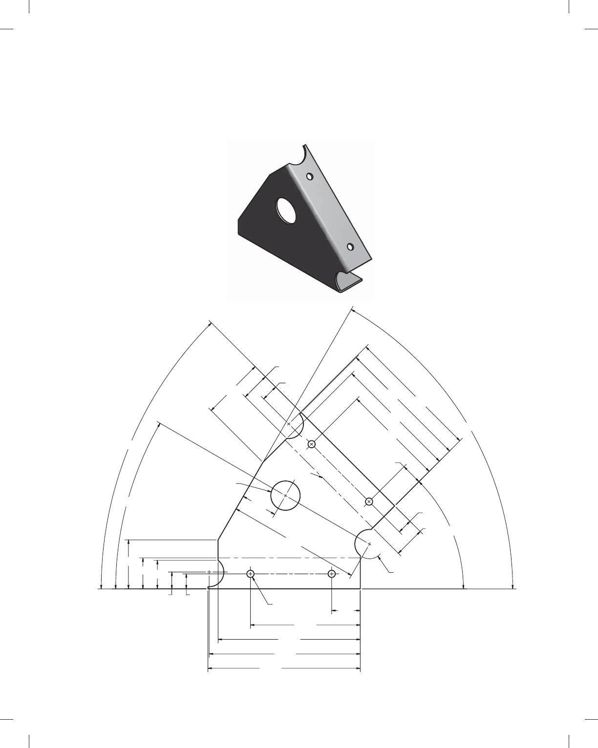
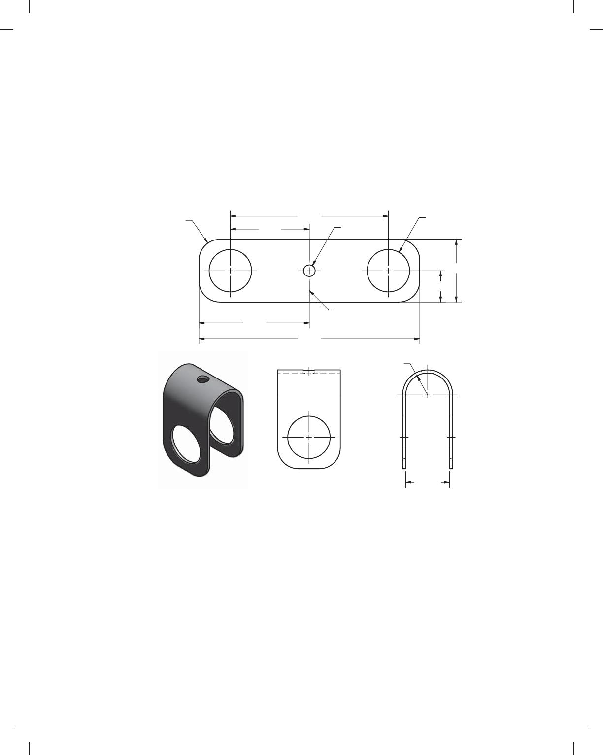
PROBLEM 19.11 3-D model and flat pattern (in.)
Part Name: Left Outer Tri-bracket
Material: 18-gauge ASTM 366
4X Ø.250 WELD
HOLE
DOWN 90° R.075
DOWN 90° R.075
3X R.508 MIN
1.070
.732
3.543
2.155
4.290
4.574
.986
.582
4.598
.520
45°
60°
1.694
1.252
4.608
3.800
.989
4.919
5.227
5.270
1.070
.986
.582 .520
45°
30°
Ø1.015 MIN
Draw the 3-D model and the flat pattern using unidirectional
dimensioning.
Courtesy 2-Kool Inc.
59728_ch19_EOC_ptg01.indd 11 03/02/16 10:35 am
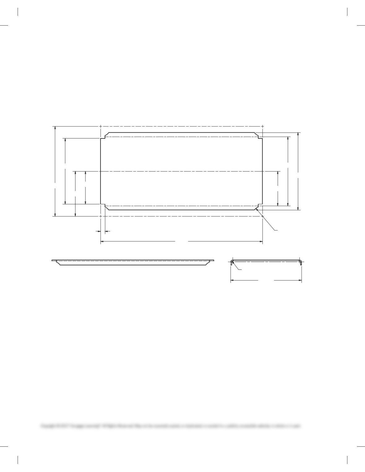
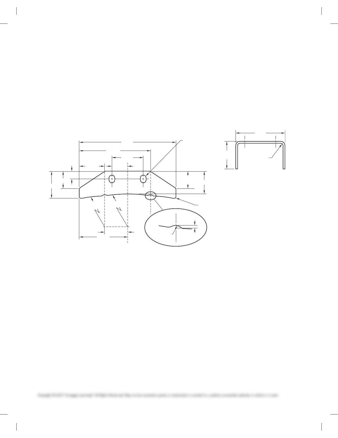
PROBLEM 19.12 Part in form view and with flat pattern (in.)
Part Name: Fender Foot Rest
Material: 18-gauge ASTM 366
Draw the form views and the flat pattern using unidirectional
dimensioning.
Courtesy 2-Kool Inc.
R.048 MIN(BEND 2X )
3.500()
3.834
1.6252X
2.2222X
BEND DOWN 90° X R.048
BEND DOWN 90° X R.048
R.508 MIN4X
3.417
1.709
4.445
.2152X
8.000
3.250
59728_ch19_EOC_ptg01.indd 12 03/02/16 10:35 am