
CHAPTER 17 BELT AND CHAIN
DRIVES PROBLEMS
BELT DRIVE PROBLEMS
Part 1: Problems 17.1 Through 17.9
Solve Problems 17.1 through 17.9 using the information and ta-
bles given in this chapter and in Table 17.1 on the next page. All
motors are AC motors with normal torque, squirrel cage, syn-
chronous, and split phase; or shunt-wound DC motors; or
DRAFTING
TEMPLATES
To access CADD template
files with predefined drafting
settings, go to the Student
Companion Website, select
Student Downloads and
Drafting Templates, and then
select the appropriate
template file.
59728_ch17_EOC_ptg01.indd 1 03/02/16 10:34 am
multiple cylinder internal combustion engines. Include the fol-
lowing information with each solution:
■ service factor,
■ design horsepower,
■ driven speed,
■ pitch diameter of driver and driven,
■ belt section,
■ number of belts,
■ belt number and center distance,
■ corrected horsepower,
■ belt drive ratio, and
■ belt velocity of driver sheave.
PROBLEM 17.1 A 3 HP, 1750 rpm motor is to operateafur-
nace blower having a shaft speed of approximately 1115 rpm
under normal service. The center distance between the motor
and blower shafts isabout 16 in.
PROBLEM 17.2 A 3 HP, 1750 rpm motor is used to operate a
drill press speed reducer under intermittent service. The spin-
dle speed is about 1136 rpm. The center distance between the
motor and spindle shafts is about 18.5 in.
PROBLEM 17.3 A 1-1/2 HP, 1750 rpm electric motor is used
to operate a woodworking band saw with the blade turning at
1144 rpm, intermittent service. The center-to-center distance
is about 16 in.
PROBLEM 17.4 A 2 HP electric motor with a shaft speedof
1750 rpm operates a printing machine at normal service. The
shaft on the printing machine is to operate at 1167 rpm. The
center-to-center distance is about 18 in.
PROBLEM 17.5 A 2 HP electric motor with a shaft speed of
1750 rpm operates a punch machine at continuous service.
The shaft on the punch machine is to operate at 1108 rpm. The
center-to-center distance is about 17 in.
PROBLEM 17.6 A 1.5 HP motor with a shaft speed of 1750 rpm
operates a compressor at normal service. The shaft on the
compressor is to operate at 1167 rpm. The center-to-center
distance is about 18 in.
PROBLEM 17.7 A 2 HP electric motor with a shaft speed of
1750 rpm operates a printing machine at normal service. The
shaft on the printing machine is to operate at 1115 rpm. The
center-to-center distance is about 17.5 in.
PROBLEM 17.8 A drive is required for an 18 HP motor
driving a fan 16 hours per day. The motor speed is 3600 rpm
and the shaft size is 1.625 in. The fan speed is approximately
2250 rpm and the fan shaft is 1.438 in. The center distance is
38 in. minimum and 41 in. maximum.
PROBLEM 17.9 Given the following layout, prepare a detail
drawing of the pulley on appropriately sized ASME sheet with
border and sheet block, unless otherwise specified by your
instructor. (Use units of inches.) Use the sheetsize, border, title
block, and tolerance instructions provided in Chapter 10,
Dimensioning and Tolerancing.
Part Name: Pulley
Material: Aluminum
1.50 12.0 18.0 A 1 10 — — — 1167 10.57 13.63 A77 15.3 0.96 A81 17.3 0.98 A85 19.4 0.99
1.50 12.0 18.0 C 2 12 — — — 1167 25.92 31.20 C75 15.1 0.82 C96 25.7 0.88 C112 33.8 0.92
1.50 13.0 19.5 A 1 3 — — — 1167 11.07 14.40 A83 16.3 0.98 A86 17.8 0.99 A89 19.4 0.99
1.51 3.7 5.6 A 1 3 2318 4.61 5.62 1159 2.94 3.71 A24 5.3 0.76 A35 10.8 0.84 A45 15.8 0.88
1.51 3.9 5.9 B 1 3 2318 4.64 8.35 1159 3.53 5.53 B28 7.1 0.73 B45 15.7 0.84 B56 21.2 0.89
1.53 3.4 5.2 B 1 6 2288 2.90 6.59 1144 2.43 4.44 B28 8.1 0.73 B45 16.6 0.84 B56 22.1 0.89
1.53 3.6 5.5 A 1 3 2288 4.42 5.37 1144 2.81 3.55 A24 5.4 0.76 A35 11.0 0.84 A45 16.0 0.88
1.53 3.6 5.5 3V 1 4 2288 6.28 7.30 1144 3.63 4.07 3V250 5.3 0.78 3V300 7.8 0.83 3V355 10.6 0.85
1.53 3.8 5.8 A 1 6 2288 4.81 5.87 1144 3.06 3.86 A24 5.0 0.76 A35 10.6 0.84 A45 15.6 0.88
1.53 3.8 5.8 B 1 6 2288 4.31 8.01 1144 3.31 5.32 B28 7.3 0.73 B45 15.8 0.84 B56 21.3 0.89
1.54 2.4 3.7 A 1 1 2273 1.85 2.12 1136 1.27 1.61 A24 7.8 0.79 A35 13.3 0.86 A45 18.3 0.90
1.54 2.6 4.0 A 1 2 2273 2.31 2.70 1136 1.54 1.94 A24 7.4 0.79 A35 12.9 0.84 A45 18.0 0.90
1.54 3.5 5.4 A 1 3 2273 4.22 5.12 1136 2.69 3.40 A24 5.6 0.76 A35 11.1 0.84 A45 16.1 0.88
1.54 3.7 5.7 A 1 3 2273 4.62 5.62 1136 2.94 3.71 A24 5.2 0.76 A35 10.7 0.84 A45 15.7 0.88
1.54 3.9 6.0 B 1 3 2273 4.66 8.36 1136 3.53 5.54 B28 7.0 0.73 B45 15.6 0.84 B56 21.1 0.89
TABLE 17.1
Nominal center distances, number of belts, and arc length factor chart.
59728_ch17_EOC_ptg01.indd 2 03/02/16 10:34 am
CHAIN DRIVE PROBLEMS
Part 2: Problems 17.10 Through 17.16
Solve Problems 17.10 through 17.16 using the information and
tables given in this chapter. Include the following information
with each solution:
■ service factor,
■ design horsepower,
■ number of teeth drive sprocket and driven sprocket,
■ chain pitch,
■ ratio,
■ center distance in chain pitches,
■ chain length, and
■ lubrication.
PROBLEM 17.10 A chain drive is required for a 1.5 HP elec-
tric motor operating a paper machine. The drive sprocket
turns 1500 rpm, and the driven sprocket turns 600 rpm. The
shaft center distance is about 19 in.
PROBLEM 17.11 A chain drive is required for a 1/10 HP
electric motor operating a speed reducer for a belt light pack–
age conveyor. The drive sprocket turns 50 rpm, and the driven
sprocket turns 17 rpm. The shaft center distance is about 17 in.
PROBLEM 17.12 A chain drive is required for a 1 HP elec-
tric motor operating a centrifuge. The drive sprocket turns
10,000 rpm, and the driven sprocket turns 4000 rpm. The shaft
center distance is about 18 in.
PROBLEM 17.13 A chain drive is required for a 2 HP elec-
tric motor operating a centrifugal pump. The drive sprocket
turns 5500 rpm, and the driven sprocket turns 1550 rpm. The
shaft center distance is about 14 in.
PROBLEM 17.14 A chain drive is required for a 2 HP elec-
tric motor operating laundry machinery. The drive sprocket
turns at 1800 rpm, which produces 900 rpm at the driven
sprocket. The approximate center distance is 12 in.
PROBLEM 17.15 A chain drive is required for a 2.5 HP inter-
nal combustion tractor engine operating a generator. The
drive sprocket turns 3000 rpm, and the driven sprocket turns
1800 rpm. The shaft center distance is about 18 in.
PROBLEM 17.16 A chain drive is required for a 2 HP elec-
tric motor operating a pure liquid agitator. The drive sprocket
turns 2100 rpm, and the driven sprocket turns 700 rpm. The
shaft center distance is about 18 in.
DIMENSIONED DETAIL DRAWINGS
Part 3: Problems 17.17 Through 17.23
PROBLEM 17.17 Chain saver (in.)
FOR 1/2
×
1 AND/OR 1
×
1 FLAT WIRE BELTS
A
A
.250
.631 .363
11.5
.879
25°
70°
1.5
.406
.250
∅
6.484 OUTSIDE DIA.
6.172 PITCH DIA.
5.703 HUB DIA.
2
SECTION A–A
UNLESS OTHERWISE SPECIFIED:
ALL FRACTIONAL DIMENSIONS
+
1/32
ALL TWO-PLACE DECIMALS
+
.010
ALL THREE-PLACE DECIMALS
+
.005
–
–
–
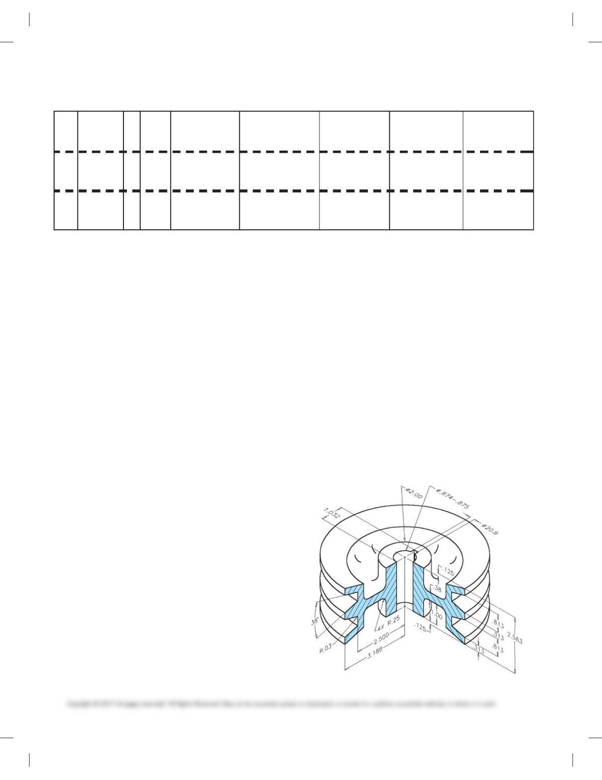
PROBLEM 17.18 FWB SD 18 sprocket (in.)
59728_ch17_EOC_ptg01.indd 3 03/02/16 10:34 am
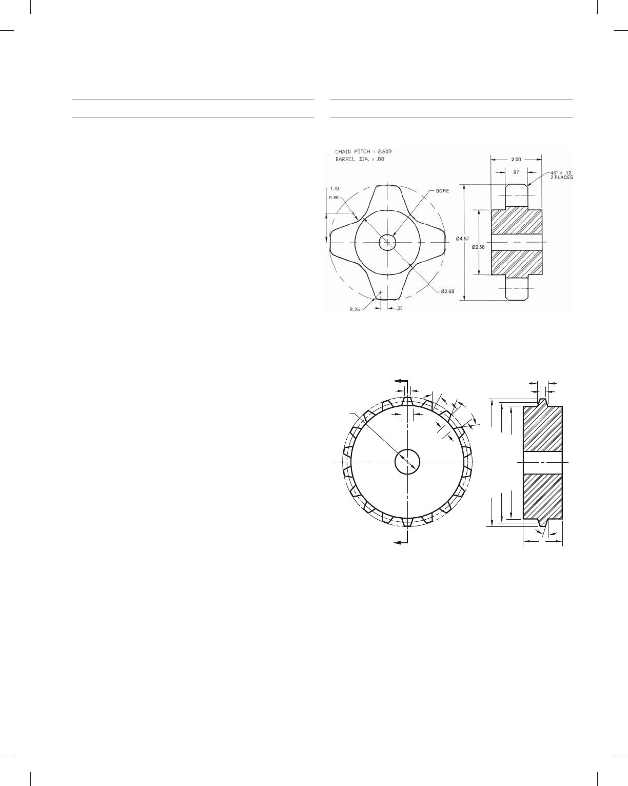
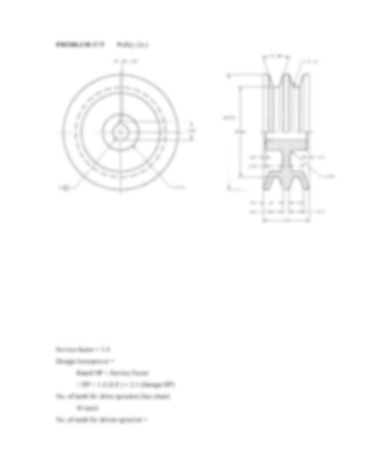
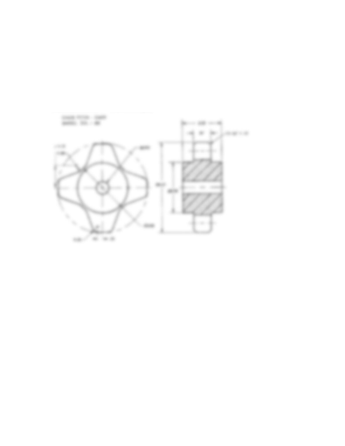
PROBLEM 17.19 Chain saver sprocket (in.)
NOTES:
1. SPROCKET CONSISTS OF (2) 6 TOOTH SEGMENTS, AND (1) 7-TOOTH SEGMENT.
2. TOLERANCES TO BE +.003/- .000 ON BD
,
ALL OTHERS ±.005.
17.05 RD
18.98
OD
18.48 PD
12 × 30°
A
SPLIT LINES
.50
12 HOLES
A
11.50 BD
13.50 BC
16.06
HUB
DIA.
∅
SECTION A–A
SCALE 2:1 3.74
.938
.75
.25
20°
10°
2.50
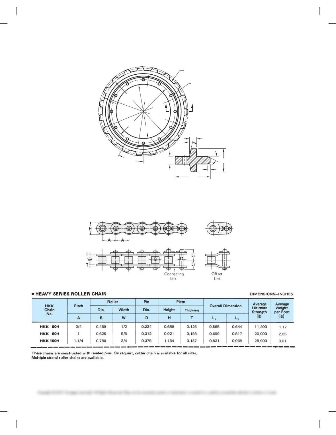
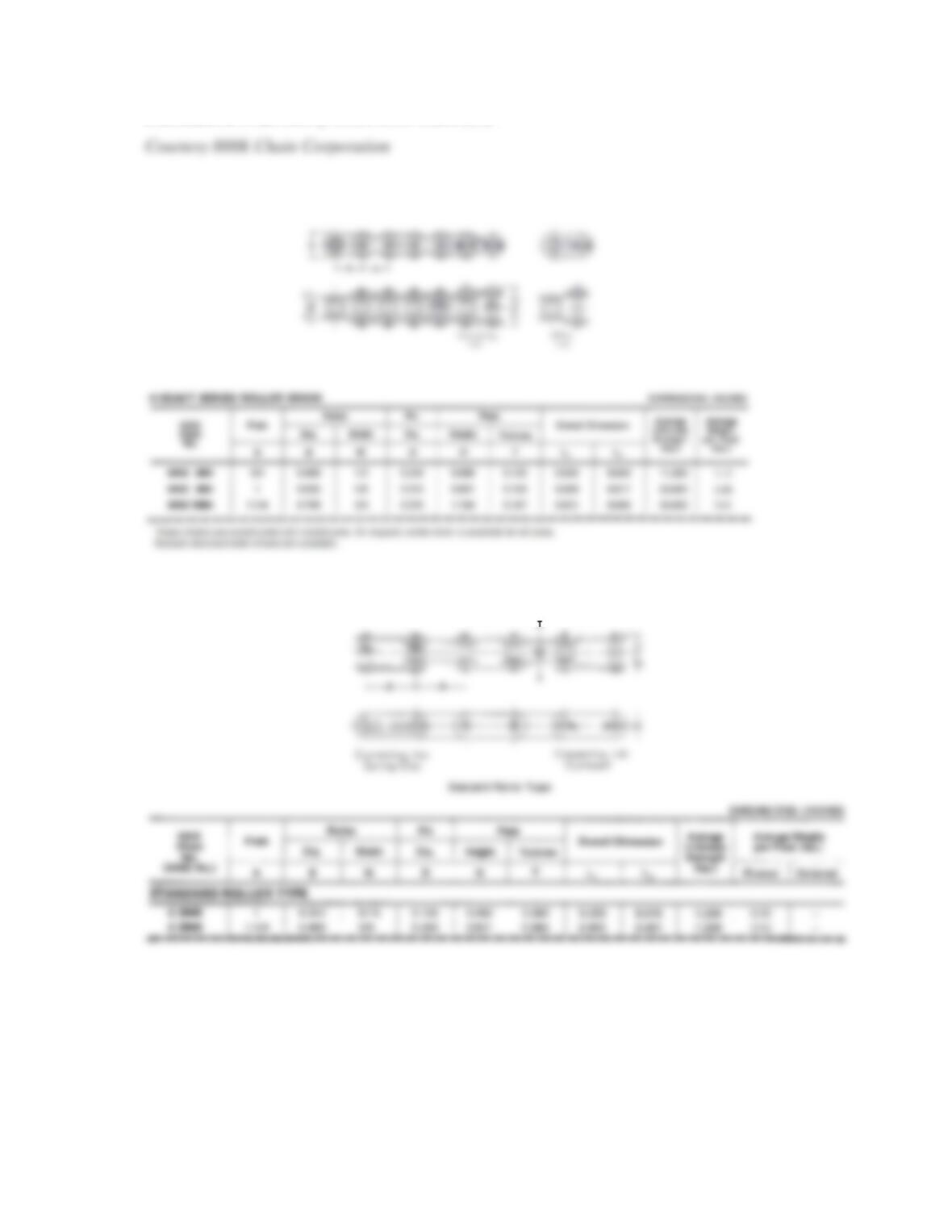
PROBLEM 17.20 Heavy series roller chain (in.) Courtesy HHK Chain Corporation.
59728_ch17_EOC_ptg01.indd 4 03/02/16 10:34 am
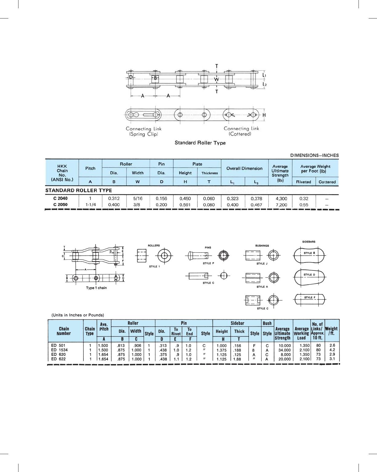
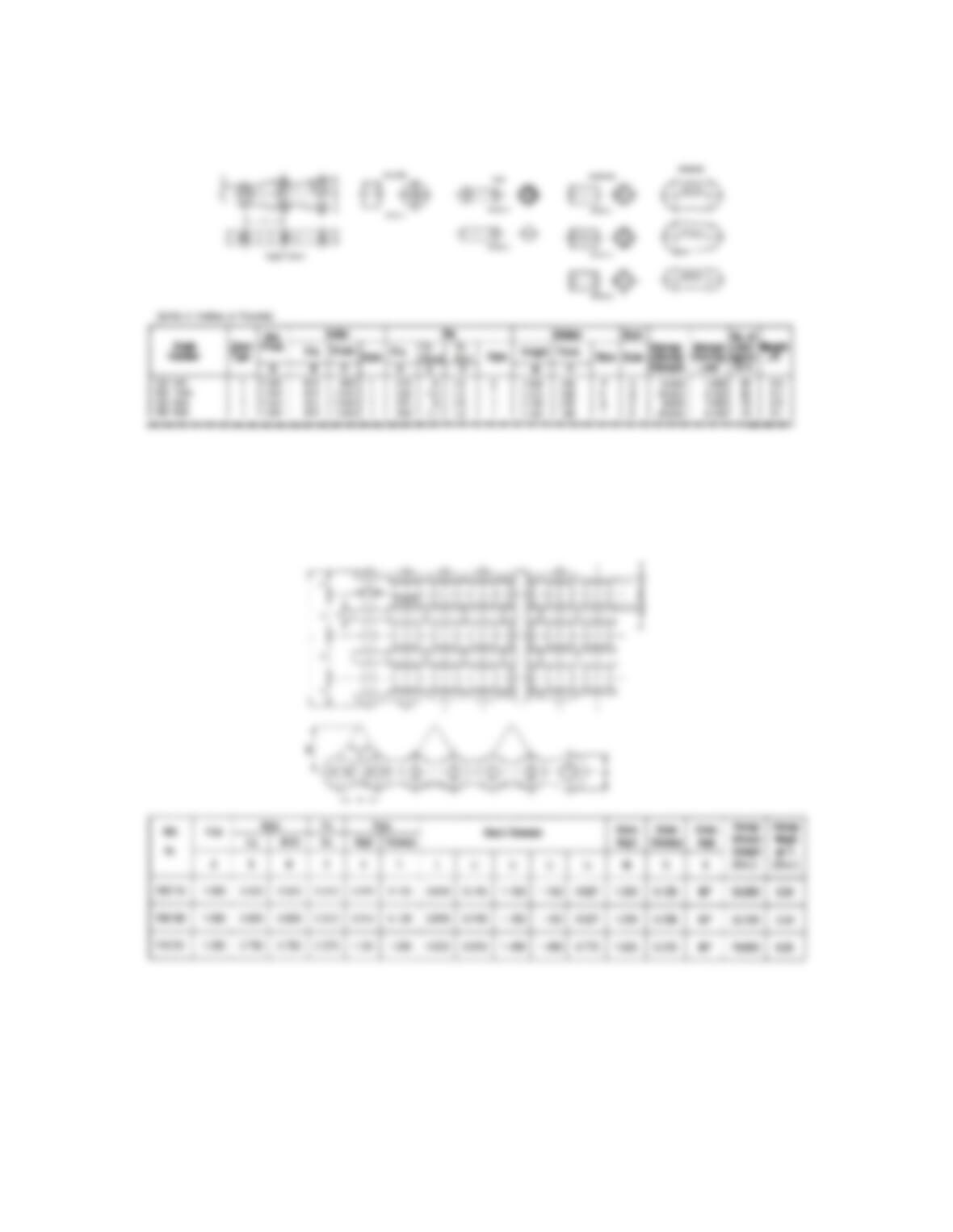
PROBLEM 17.21 Conveyor-type standard roller chain (in.)
p
PROBLEM 17.22 Offset sidebar chain (in.)
59728_ch17_EOC_ptg01.indd 5 03/02/16 10:34 am
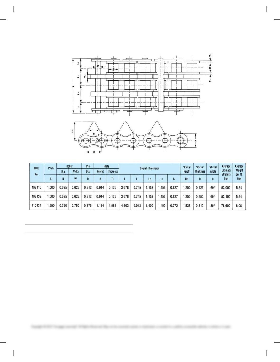
PROBLEM 17.23 Sticker chain for the forest industries (in.)
MATH PROBLEMS
Part 4: Problems 17.24 Through 17.29
Find the belt length fxor these pulley radii and center-to-center
distances:
PROBLEM 17.24 r 5 80, R 5 100, d 5 270
PROBLEM 17.25 r 5 120, R 5 120, d 5 1000
PROBLEM 17.26 r 5 50, R 5 300, d 5 400
PROBLEM 17.27 r 5 70, R 5 150, d 5 300
PROBLEM 17.28 r 5 40, R 5 80, d 5 350
PROBLEM 17.29 r 5 101.6 mm, R 5 203.2 mm, d 5 889 mm
59728_ch17_EOC_ptg01.indd 6 03/02/16 10:34 am
312
Chapter 17
Belt and Chain Drives
Solutions to End-of Chapter Problems
Belt Drive Problems
Part 1: Problems 17.1 Through 17.9
PROBLEM 17.1
313
PROBLEM 17.2
PROBLEM 17.3
314
PROBLEM 17.4
315
PROBLEM 17.5
316
PROBLEM 17.6
PROBLEM 17.7

317
PROBLEM 17.8
In conclusion, the design solution to the sample problem is as follows:
318
Chain Drive Problems
Part 2: Problems 17.10 Through 17.16
PROBLEM 17.10 No solution provided.
PROBLEM 17.11 No solution provided.
PROBLEM 17.12
319
PROBLEM 17.13 No solution provided.
PROBLEM 17.14
320
PROBLEM 17.15 No solution provided.
PROBLEM 17.16 No solution provided.
Part 3: Problems 17.17 Through 17.23
PROBLEM 17.17 Chain saver (in.)

321
PROBLEM 17.18 FWB SD 18 sprocket (in.)
322
PROBLEM 17.20 Heavy series roller chain (in.)
PROBLEM 17.21 Conveyor-type standard roller chain (in.)
323
PROBLEM 17.22 Offset sidebar chain (in.)
PROBLEM 17.23 Sticker chain for the forest industries (in.)
324
Math Problem Solutions
Part 4: Problems 17.24 Through 17.29