CHAPTER16 MECHANISMS:
LINKAGES, CAMS, GEARS,
ANDBEARINGS PROBLEMS
INSTRUCTIONS
Read each problem carefully before you begin working. Com-
plete each problem on an appropriately sized sheet with a border
and sheet block of your choice unless otherwise specified by your
instructor.
LINKAGE PROBLEMS
Print each problem page at 100% for use in making measure-
ments from the hard copy.
Part 1: Problems 16.1 Through 16.14
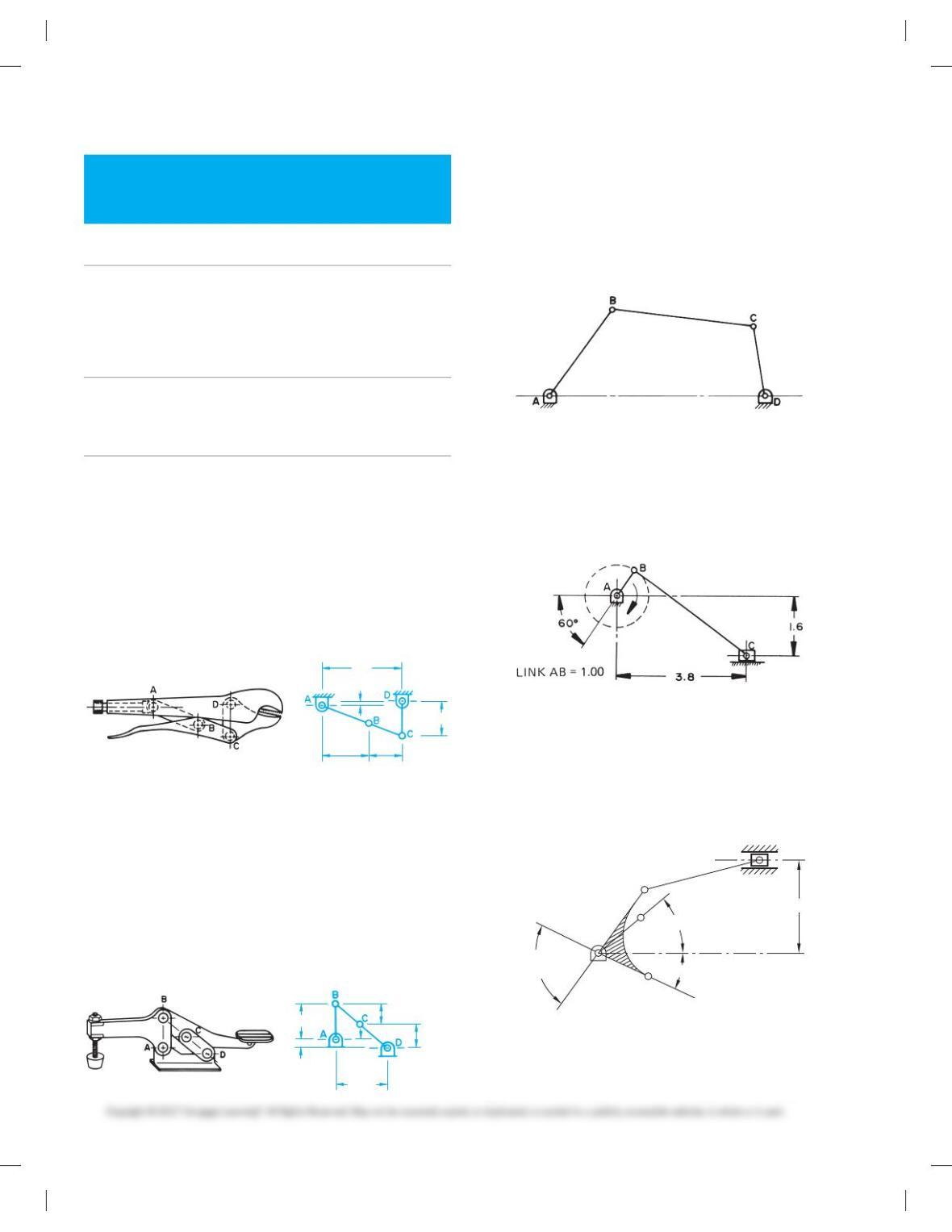
PROBLEM 16.1 Refer to the pictorial drawing and a linkage
schematic of a vise grip in the closed position. Reproduce the
schematic exactly as shown and also show the open position in
a second color.
A-B 5 2.5 IN
B-C 5 1.75 IN
C-D 5 1.75 IN
A-D vertical .25 IN
A-D horizontal 4.0 IN
2.5 1.75
4.0
.25
1.75
PROBLEM 16.2 Refer to the pictorial drawing and a linkage
schematic of a toggle clamp in the closed position. Reproduce
the schematic exactly as shown and also show the open posi-
tion in a second color.
A-B 5 1.7 IN
B-C 5 1.6 IN
C-D 5 1.75 IN
A-D vertical .4 IN
A-D horizontal 2.6 IN
1.7 IN 1.6 IN
1.75 IN
.4 IN
2.6 IN
PROBLEM 16.3 Determine the extreme right and left posi-
tions of link CD in the given problem. Determine and label the
angle through which CD oscillates. Measure the problem
drawing using a 1/20 5 19200 scale and transfer the measure-
ments to your final drawing.
PROBLEM 16.4 Draw the mechanism in the position
shown. Use different colors to draw the mechanism in the ex-
treme right and left positions. Dimension the stroke (in.).
PROBLEM 16.5 Draw the combination bell crank slider
mechanism in the position shown. Determine the stroke of the
slider if A moves to position A1. Note: Position of features in
the sketch may be out of proportion (in.).
408
258
ANGLE ABC=
808
D
C
B
AB = 1.500″
BC = 2.125″
CD = 3.375″
A’
A
1.625″
PROBLEM 16.6 The given drawing is a linkage schematic of
an oscillating lawn sprinkler. The spray tube, shown in section,
is part of link CD. Link AB moves through 3608, while points A
59728_ch16_EOC_ptg01.indd 2 2/3/16 2:25 PM
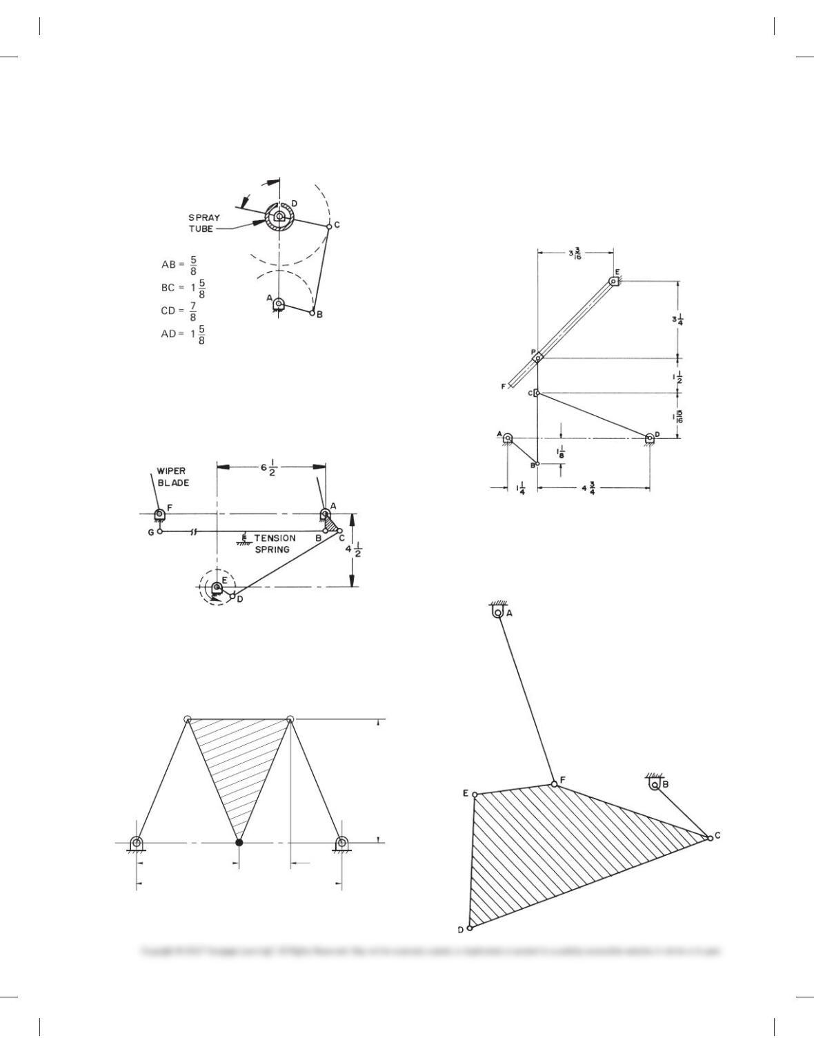
through a total of 3608. Use a different color or line type or
both for each position (in.).
Dimension the angle through which CD oscillates.
BCP is a through link.
Point P slides on EF.
EF 5 6.5 IN
PROBLEM 16.7 Given the windshield wiper mechanism, de-
termine and dimension the angle of oscillation of the wiper
blades. The electric motor rotates link ED continuously
through 3608. ABC is one link with a 908 angle at B. A tension
spring is located in the center of link BG.
PROBLEM 16.8 Draw the given mechanism. Use different
colors to show the path of point D in a total of five equally
spaced positions, including the extreme right and left posi-
tions (in.).
B
C
A
D
E
21
4
2.5
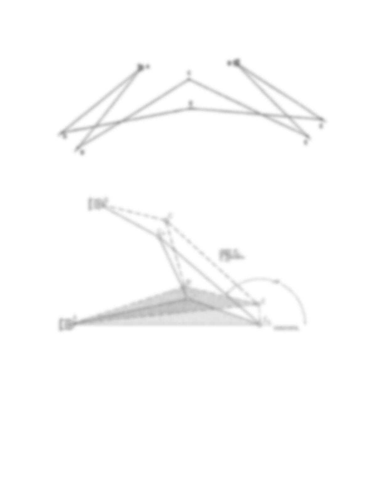
PROBLEM 16.9 Draw the mechanism in the given position.
Draw the path of point P as linkage AB moves every 308
PROBLEM 16.10 Given the mechanism, rotate link BC at
608 intervals clockwise through 3608. Plot and draw the paths
of points D, E, and F. Dimension the angle of oscillation of link
AF. Measure the problem drawing using a 1/20 5 19 2 00 scale
and transfer the measurements to your final drawing.
and D are stationary. Determine and dimension the angle of
oscillation through which the spray moves (in.).
59728_ch16_EOC_ptg01.indd 3 2/3/16 2:25 PM
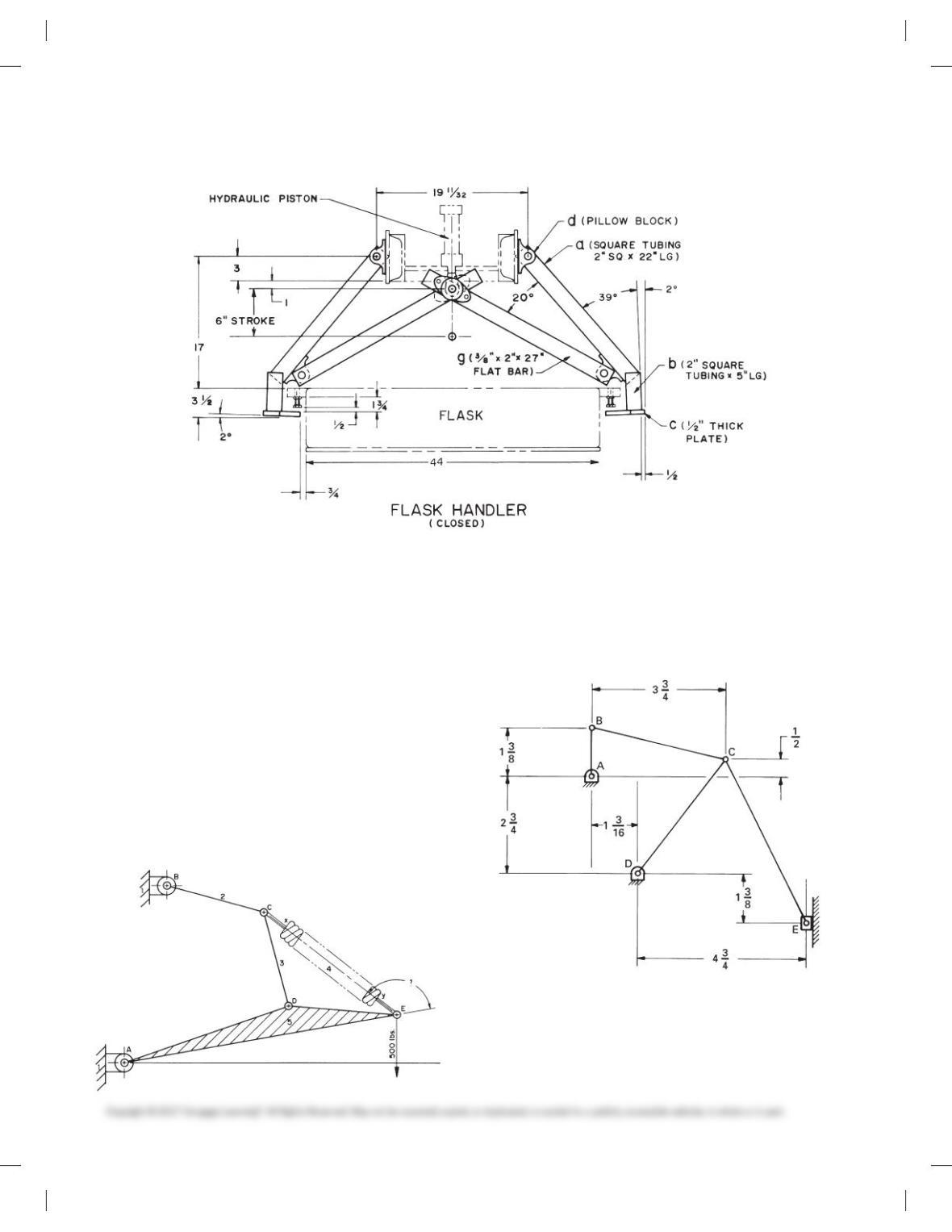
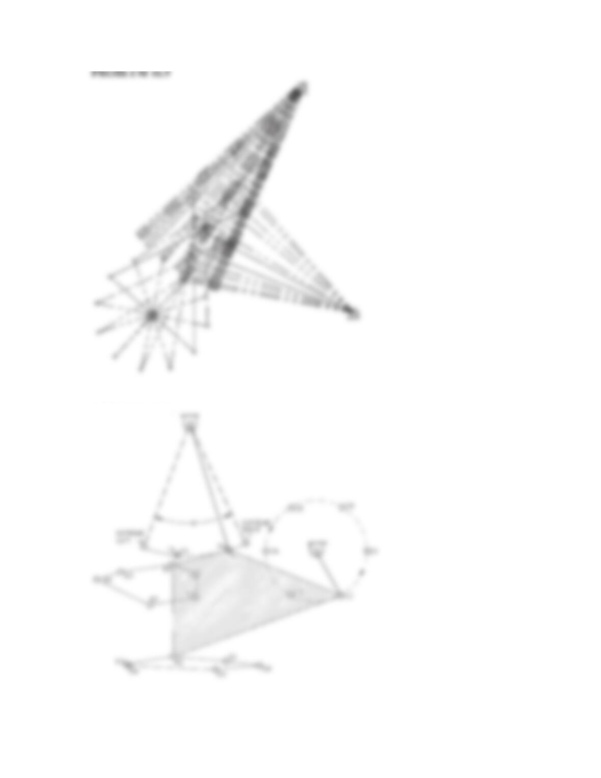
PROBLEM 16.11 Given the assembly drawing of the
foundry flask handler, draw a mechanism schematic showing
the two extreme positions of movement. The handler is oper–
ated by a hydraulic piston with a 6 IN stroke.
a is welded to b.
b is welded to c (in.).
PROBLEM 16.12 Given the pivot hoist, measure and draw
exactly as shown using a 1/40 5 19 2 00 scale and transfer the
measurements to your final drawing. Rotate ADE clockwise so
link AE is horizontal. Determine and dimension the extended
length of the spring between C and E. Determine and dimen-
sion the angle between AE and CE when E is in the new
position.
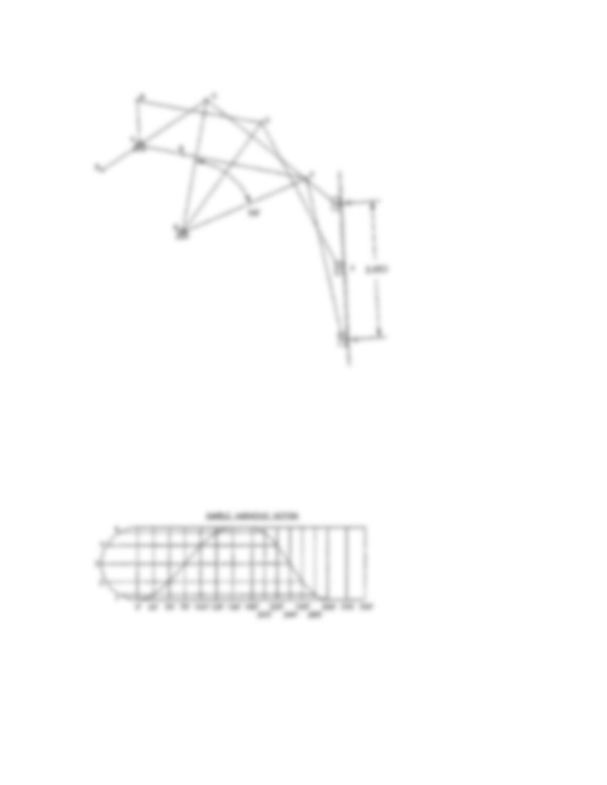
PROBLEM 16.13 Given the linkage drawing, determine and
dimension the stroke of point E moving in a straight line as
link AB rotates 3608. In addition, dimension the angle of oscil-
lation of link CD (in.).
PROBLEM 16.14 Find two examples of linkage mecha-
nisms at home or school. Explain in a short complete state-
ment the function of each mechanism. Use schematic
representations to show and dimension the extreme posi-
tions of each mechanism.
PROBLEM 16.10
(Continued)
59728_ch16_EOC_ptg01.indd 4 2/3/16 2:25 PM

CAM-DISPLACEMENT DIAGRAMS
Part 2: Problems 16.15 Through 16.25
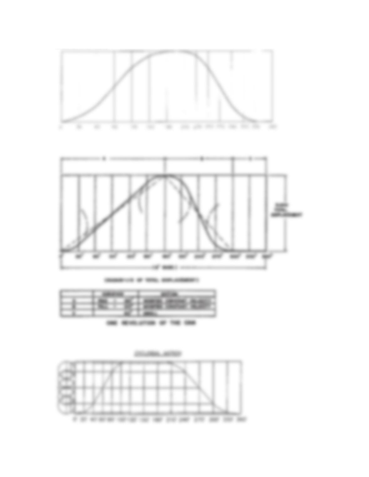
PROBLEM 16.15 Construct a cam-displacement diagram for
a cam follower that rises in simple harmonic motion a total of
2.00 in. in 1508, dwells for 308, falls 2.00 in. simple harmonic mo-
tion in 1208, and dwells for 608. Draw the horizontal scale 6.00 in.
PROBLEM 16.16 Construct a cam-displacement diagram
for a cam follower that rises in uniform accelerated motion a
total of 2.00 in. in 1808, dwells for 308, falls 2.00 in. uniform ac-
celerated motion in 1208, and dwells for 308. Draw the horizon-
tal scale 6.00 in.
PROBLEM 16.17 Construct a cam-displacement diagram
for a cam follower that rises in modified constant velocity for
3.00 in. in 1808, falls 3.00 in. modified constant velocity motion
in 1208, and dwells for 608. Use a modified constant velocity
motion designed with one-third of the displacement.
PROBLEM 16.18 Construct a cam-displacement diagram
for a cam follower that rises 2.000 in. cycloidal motion in 1208,
dwells for 608, and falls 2.000 in. in cycloidal motion in 1808.
PROBLEM 16.19 Construct a cam-displacement diagram
for a cam follower that rises in simple harmonic motion a total
of 1.250 in. in 908, dwells for 608, rises .750 in. in 458 simple har–
monic motion, and falls 2.00 in. with cycloidal motion in 1208.
Draw the horizontal scale 12 in.
PROBLEM 16.20 Construct a cam-displacement diagram for
a cam follower that rises in modified constant velocity motion
(modified to one-third the displacement) for 3.000 in. in 1808,
dwells for 308, falls 3.000 in. simple harmonic motion in 1208, and
dwells to the end of the cycle. Draw the horizontal scale 12 in.
PROBLEM 16.21 Construct a cam-displacement diagram
for a cam follower that rises 3.500 in. in 908 cycloidal motion,
dwells for 458, falls 2.500 in. cycloidal motion in 1358, dwells for
308, falls 1.000 in. simple harmonic motion in 308, and dwells to
the end of the cycle. Draw the horizontal scale 12 in.
PROBLEM 16.22 Construct a cam-displacement diagram
for a cam follower that rises in cycloidal motion for 3.000in. in
908, dwells for 308, falls 1.000 in. in simple harmonic motion in
908, dwells for 308, and falls the remaining 2.000 in. in uniform
accelerated motion in 1208. Draw the horizontal scale 12 in.
PROBLEM 16.23 Construct a cam-displacement diagram
for a cam follower that rises in cycloidal motion a total of
2.1875 in. in 1508, dwells for 308, falls back to the original level
in simple harmonic motion in 1508, then dwells through the re-
mainder of the cycle. Use a 12 in. horizontal scale.
PROBLEM 16.24 Construct a cam-displacement diagram
for a cam follower that rises a .375 in. diameter inline roller fol-
lower 1.500 in. in uniform accelerated motion in 1508, dwells
458, falls with modified constant velocity (one-third displace-
ment) in 1208, and dwells the remainder of the cycle.
PROBLEM 16.25 Construct a cam-displacement diagram for
a cam follower that rises 3.500 in. in 908 cycloidal motion, dwells
for 308, falls 2.250 in. cycloidal motion in 1508, falls 1.250 in. sim-
ple harmonic motion in 608, and dwells for 308. Draw the hori-
zontal scale equal in circumference to a 3.000 in. diameter circle.
CAM PROFILE DRAWINGS
Part 3: Problems 16.26 Through 16.31
1. For the following problems requiring detail drawings use an
appropriate ASME sheet size with border and sheet blocks.
2. Draw and completely dimension the necessary views.
3. Provide a cam-displacement chart for cam drawings and
gear data chart for gear drawings.
4. Include the following general notes at the lower-left corner
of the sheet .5 in. each way from the corner border lines:
NOTES:
1. DIMENSIONING AND TOLERANCING PER ASME
Y14.5-2009.
2. REMOVE ALL BURRS AND SHARP EDGES.
Additional general notes can be required depending on the
specifications of each individual assignment. Use the follow-
ing for tolerances for unspecified inch values. A tolerance
block is recommended as described in Chapter 2 Drafting
Equipment, Media, and Reproduction Methods and shown in
problems for Chapter 10 Dimensioning and Tolerancing un-
less otherwise specified.
Unspecified Tolerances
Decimals In.
X6.1
XX 6.01
XXX 6.005
ANGULAR 6309
FINISH 125 μin.
For metric drawings, provide a general note that states TOL-
ERANCES FOR UNSPECIFIED DIMENSIONS COMPLY WITH
ISO 2768-m. Provide a general note that states SURFACE FINISH
3.2 mm UNLESS OTHERWISE SPECIFIED.
DRAFTING
TEMPLATES
To access CADD template
files with predefined drafting
settings, go to the Student
Companion Website, select
Student Downloads and
Drafting Templates, and then
select the appropriate
template file.
59728_ch16_EOC_ptg01.indd 5 2/3/16 2:25 PM
PROBLEM 16.26 Use the displacement diagram con-
structed in Problem 16.15 and the information given in the il-
lustration to lay out the plate cam profile drawing. The cam
rotates counterclockwise. Make a two-view detailed drawing of
the cam and dimension it as shown in this chapter (in.).
INLINE ROLLER FOLLOWER
BASE CIRCLE
KEY SIZE USED
PLATE THICKNESS
HUB THICKNESS
HUB DIAMETER
SHAFT DIAMETER
.625
.626
[
.500
1.25
-28UNF-2B
[1.375
08
[.750
1
4
[.750
[2.000
1/4 3 1/4 SQ. KEY
.500
.750
[1
.375
[.625/.626
=
=
=
=
=
=
=
PROBLEM 16.27 Use the displacement diagram constructed
in Problem 16.18 and the information given in the illustration
for Problem 16.26 to lay out the plate cam profile. The cam is ro-
tating counterclockwise. Make a two-view detailed drawing of
the cam, properly dimensioned and toleranced.
PROBLEM 16.28 Make a two-view detailed drawing of a
plate cam using the displacement diagram from Prob-
lem16.24. Completely dimension the drawing using the follow-
ing information:
The cam rotates counterclockwise.
Inline roller follower 5 [.375
Base circle 5 [2.750
Shaft 5 [1.000
Hub diameter 5 [1.250
Hub projection 5 .500
Plate thickness 5 .375
All dimensions in inches.
PROBLEM 16.29 Make a two-view detailed drawing of a
plate cam using the displacement diagram from Prob-
lem16.20. Completely dimension the drawing using the follow-
ing information:
The cam rotates counterclockwise.
Inline roller follower 5 [.750
Base circle 5 [2.000
Shaft 5 [.625
Hub diameter 5 [1.250
Hub projection 5 .500
Plate thickness 5 .500
All dimensions in inches.
PROBLEM 16.30 Make a two-view detailed drawing of a
plate cam using the displacement diagram from Problem 16.18.
Completely dimension the drawing using the information
shown below (in.).
.75
1.00
.50
Ø.750
Ø.625
Ø1.250
Ø2.000
BASE CIRCLE
PROBLEM 16.31 Use the displacement diagram con-
structed in Problem 16.25 and the following illustration to lay
out the profile of the groove in the drum cam. The cam rotates
clockwise. Make a two-view detailed drawing of the drum cam,
with tolerances and dimensions as discussed and shown in
this chapter (in.).
Ø3.00
5.00
.500
.375 (GROOVE DEPTH)
.500
.750
3/8-24 UNF-2B
WIDTH)
(GROOVE
.504
.501
.156
Ø1.250
HALF OF OBJECT SHOWN
59728_ch16_EOC_ptg01.indd 6 2/3/16 2:25 PM
GEAR PROBLEMS
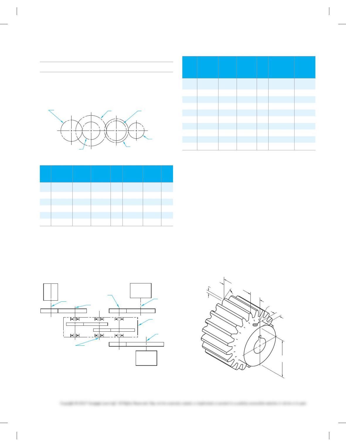
Part 4: Problems 16.32 Through 16.37
PROBLEM 16.32 Given the gear train and chart, calculate
or determine the missing information to complete the chart.
GEAR A GEAR C GEAR D
GEAR F
GEAR E
GEAR B
Gear
Diametral
Pitch
(P)
Number
of Teeth
(N)
Pitch
Diameter
(D) RPM Direction
Center
Distance
Gear
Ratio
A 4 7.5” 240 Clockwise
B18
C 10.0” 400
D540
E7
F 14 1500
Gear
Pitch
Diameter
No. of
Teeth
Diametral
Pitch RPM
Ctr. Distance
Between
Mating
Gears Direction
A 3.00 3600 Counter–
clockwise
B 5 4.00
C 48
D 12 1080
E 4.00 40
F100
G 5.00 6.00
H 6
I 4
J 40 108
PROBLEM 16.33 Given the 10-gear power transmission and
chart, calculate or determine the missing information to com-
plete the chart.
SHAFT
5
SHAFT 2
SHAFT 1
MOTOR
MACHINE
“A”
SHAFT 4
HOUSING
SHAFT
6
SHAFT 3
MACHINE
“B”
AB
CD
EF
G
IJ
H
PROBLEM 16.34 Given the following information, use
ASME standards to make a detail drawing of the spur gear us-
ing the instructions provided with these problems (in.):
20 teeth
Diametral pitch 5 5
208 pressure angle
Face width 5 2.500 IN
Shaft diameter 5 [1.125
Keyway for a .25 IN square key
Place the centerline of the keyway in line with a radial line
through the center of one tooth (one tooth profile needed to
show alignment). Include the necessary spur gear data in a chart
placed over the title block. Use the formulas given in this chapter
to solve for unknown values.
2.500 .875
Ø3.00
2X .12
2X 308
5/16-18 UNC-2B
.44
MATERIAL: SAE 4320
59728_ch16_EOC_ptg01.indd 7 2/3/16 2:25 PM
MATERIAL: SAE 4320
1.750 2.00
2.500
PROBLEM 16.36 Use ASME standards to make a detail
drawing of a straight bevel gear given the following informa-
tion and the illustration shown below (in.):
Pitch diameter 5 [8.000 in.
Pressure angle 5 208
32 teeth
Diametral pitch 5 4
Face width 5 1.400
Shaft diameter 5 [1.125 in.
Use a .250 square key.
Core distance 5 4.401
Circular thickness 5 4.0939
Pitch angle 5 658
Root angle 5 62.158
Addendum 5 .3022
Whole depth 5 .5493
Chordal addendum 5 .0496
Chordal thickness 5 .7841
5/16–13UNC–2B
1.563 2.688
4.250
MOUNTING
DISTANCE
3.750
[
(8.233)
PROBLEM 16.37 Prepare a detail drawing of the pinion and
gear using the following gear data.
Dimensions for 208 straight bevel gear 908 shaft angle
Feature Pinion Gear
Number of teeth 22 75
Diametral pitch 10 10
Face width 1.25 1.25
Pressure angle 208208
Shaft angle 908908
Working depth 0.200 0.200
Whole depth 0.221 0.221
Pitch diameter 2.200 7.500
Pitch angle 16.3488 73.6528
Cone distance 3.908 3.908
Circular pitch 0.314 0.314
Addendum 0.142 0.058
Dedendum 0.077 0.161
Clearance 0.021 0.021
Dedendum angle 1.12682.3568
Face angle of blank 18.704874.7788
Root angle 15.222871.2968
Outside diameter 2.473 7.533
Pitch apex to crown 3.710 1.044
Circular thickness 0.188 0.126
Backlash 0.002 0.002
Chordal thickness 0.186 0.125
Chordal addendum 0.146 0.058
Tooth angle 107.149 min 107.149 min
Limit point width 0.046 0.046
Tool advance 0.002 0.002
BEARING PROBLEMS
Part 5: Problems 16.38 Through 16.41
PROBLEM 16.38 Use the charts shown in this chapter to
establish the following medium-service bearing dimensions
for an approximate [1.25 in. shaft. Use a word processor to
type the problem number and the answer for each required
item.
Bearing catalog number ________________________________
Bore ________________________________________________
Outside diameter _____________________________________
Width ______________________________________________
Fillet radius __________________________________________
Shaft shoulder diameter ________________________________
PROBLEM 16.35 Use ASME standards to make a detail draw-
ing of a rack that mates with the spur gear in Problem 16.34.
Use the instructions provided with these problems. The overall
length is 24 in.
59728_ch16_EOC_ptg01.indd 8 2/3/16 2:25 PM
Housing shoulder diameter ______________________________
Shaft diameter _______________________________________
Housing diameter_____________________________________
PROBLEM 16.39 Use the charts shown in this chapter to es-
tablish the following medium-service bearing dimensions for
an approximate [3.5 in. shaft. Use a word processor to type
the problem number and the answer for each required item.
Bearing catalog number ________________________________
Bore ________________________________________________
Outside diameter _____________________________________
Width ______________________________________________
Fillet radius __________________________________________
Shaft shoulder diameter ________________________________
Housing shoulder diameter _____________________________
Shaft diameter _______________________________________
Housing diameter _____________________________________
PROBLEM 16.40 Use the charts shown in this chapter to es-
tablish the following medium-service bearing dimensions for
an approximate [20 mm shaft. Use a word processor to type
the problem number and the answer for each required item.
Bearing catalog number ________________________________
Bore ________________________________________________
Outside diameter _____________________________________
Width ______________________________________________
Fillet radius __________________________________________
Shaft shoulder diameter ________________________________
Housing shoulder diameter _____________________________
Shaft diameter _______________________________________
Housing diameter _____________________________________
PROBLEM 16.41 Use the charts shown in this chapter to es-
tablish the following medium-service bearing dimensions for
an approximate [60 mm shaft. Use a word processor to type
the problem number and the answer for each required item.
Bearing catalog number ________________________________
Bore ________________________________________________
Outside diameter _____________________________________
Width ______________________________________________
Fillet radius __________________________________________
Shaft shoulder diameter ________________________________
Housing shoulder diameter _____________________________
Shaft diameter _______________________________________
Housing diameter _____________________________________
LINKAGE DESIGN PROBLEMS
Part 6: Problems 16.42 and 16.43
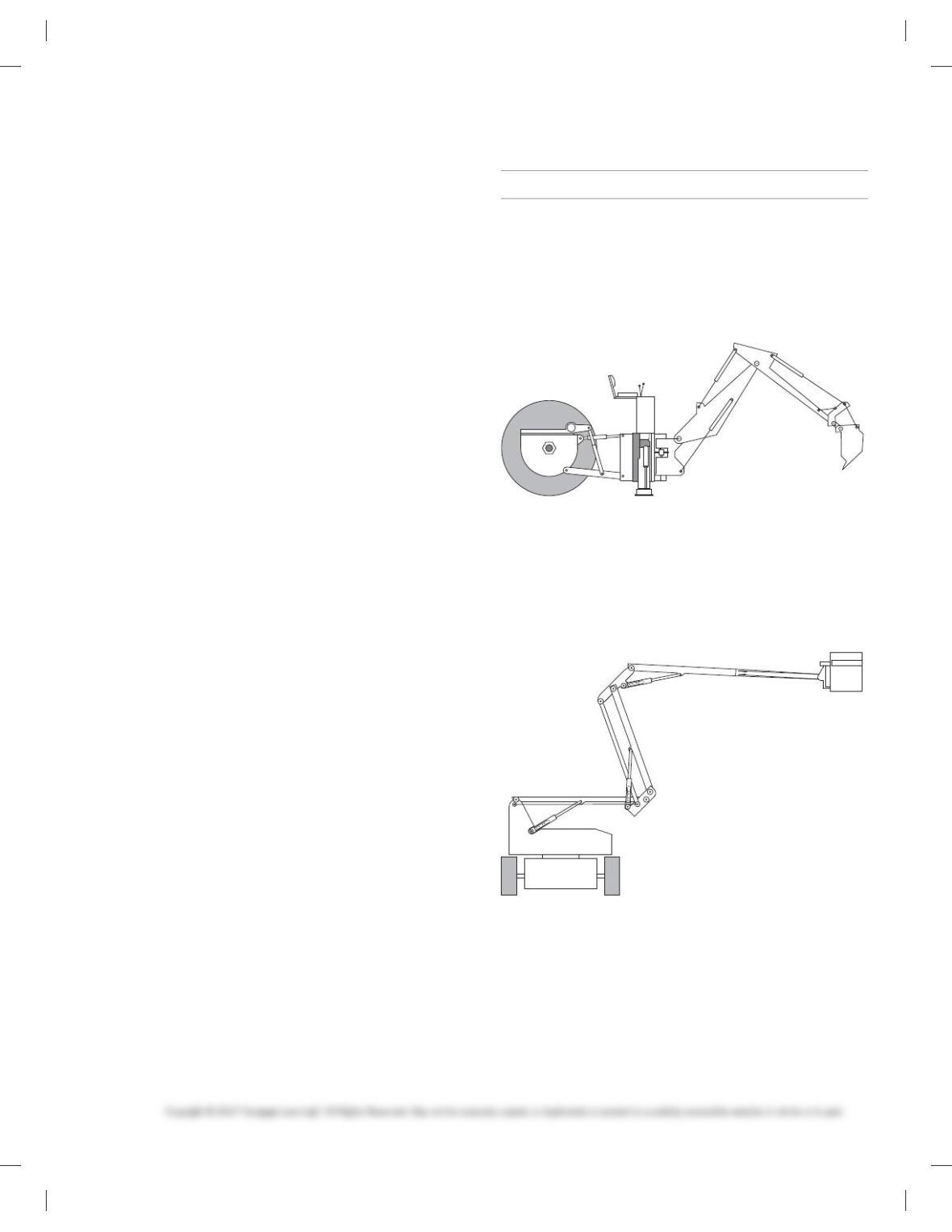
PROBLEM 16.42 Given the following drawing as an exam-
ple, design a backhoe that can dig a 20-ft.-deep trench. Draw
an assembly drawing with dimensions specified between link–
ages. Show the backhoe in the fully closed position, half ex-
tended position, fully extended horizontal, and fully extended
at the maximum trench depth.
PROBLEM 16.43 Given the following drawing as an exam
ple, design a similar material handling lift that can lift a maxi-
mum of 12 ft. vertically and 16 ft. horizontally. The telescoping
actuator can operate a maximum 4-ft. extension.
59728_ch16_EOC_ptg01.indd 9 2/3/16 2:25 PM
GEAR DESIGN, BEARING SELECTION,
SHAFT DESIGN PROBLEM
Part 7: Problem 16.44
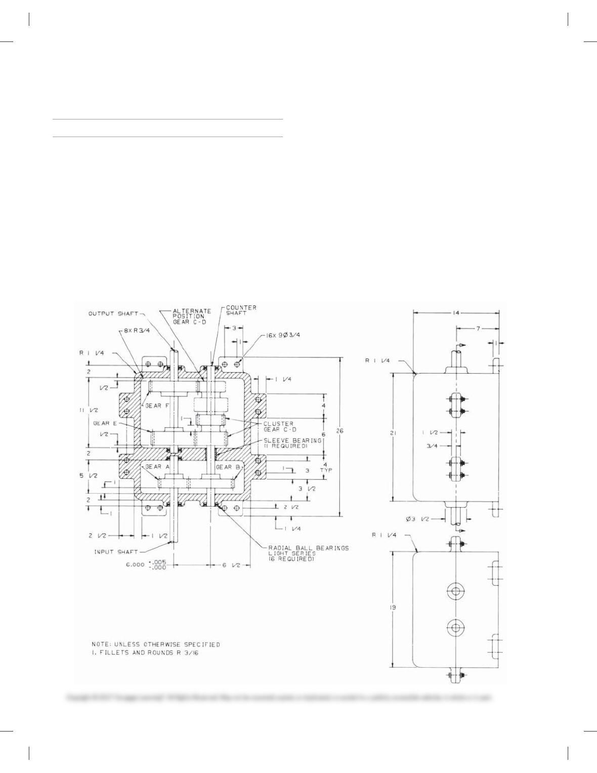
PROBLEM 16.44 Design a two-speed gear reducer that will
operate eight to ten hours per day and receive moderate shock
while in operation. Use the following information:
■ A 5-HP 1750 electric motor supplies the input power.
■ There are six gears arranged approximately as shown on the
following drawing.
■ Gear C-D is a cluster gear sliding on the countershaft.
■ The output speed is 625 rpm when gear C is engaged with gear E.
■ The output speed is 437.5 rpm when gear D is engaged with
gear F.
■ Gear A has 32 teeth, gear B has 64 teeth, gear C has 25 teeth,
and gear D has 24 teeth.
Use the gear and bearing information from this chapter to design
the gear reducer and do the following:
1. Determine the diametral pitches for all six gears.
2. Determine the number of teeth for gears E and F.
3. Use tolerances, surface finishes, and fit as discussed in this
chapter.
4. Use manufacturers’ catalogs shown in this chapter or sup-
plied by your instructor to select standard parts.
5. Make a detailed drawing of the cluster gear, including spur
gear data charts for both gears on one sheet.
6. Make detailed drawings of the three shafts—input, output,
and countershaft—each on a separate sheet. The shafts are
approximately [1.250 in. Design the shafts based on bear–
ing specifications and fits. Design the keyseats based on the
shaft diameter given and as specified in the Machinery’s
Handbook or other source.
59728_ch16_EOC_ptg01.indd 10 2/3/16 2:25 PM
MATH PROBLEMS
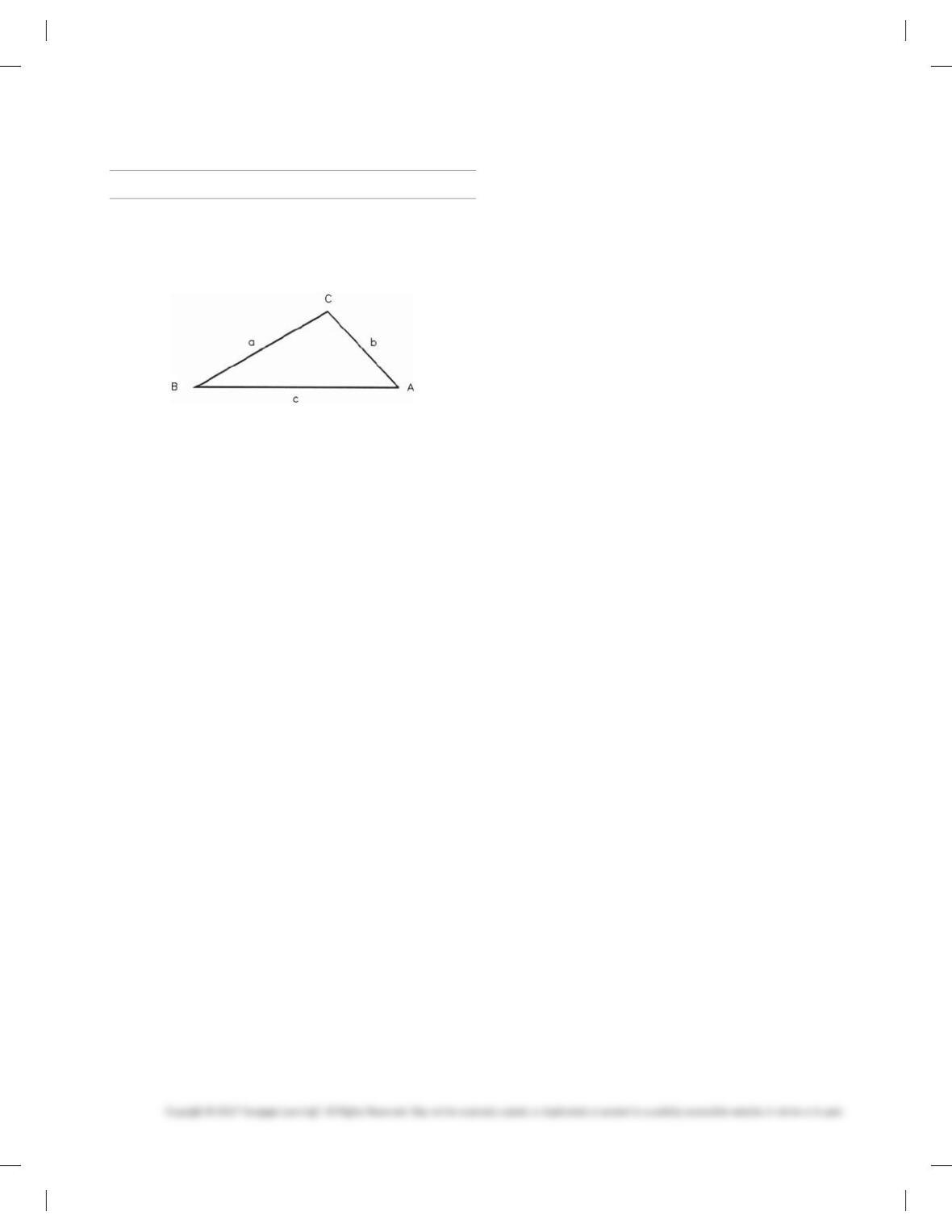
Part 8: Problems 16.45 Through 16.50
For the oblique triangle shown below (which is not drawn
to scale):
PROBLEM 16.45 Find side b given a 5 125, A 5 54.78,
B 5 65.28.
PROBLEM 16.46 Find side c given b 5 321, A 5 75.38,
C 5 38.58. (Hint: A 1 B 1 C 5 1808.)
PROBLEM 16.47 Find angle C given b 5 50.4, c 5 33.3,
B 5 118.58.
PROBLEM 16.48 Find angle A given b 5 51.5, a 5 62.5, B 5
40.78, and given that angle A is greater than 908.
PROBLEM 16.49 Find side b given a 5 320, c 5 475,
A 5 35.38, and given that angle C is less than 908.
(Hint: Find angle C first.)
PROBLEM 16.50 Find side a given b 5 50.4, c 5 33.3,
B 5 118.58.
59728_ch16_EOC_ptg01.indd 11 2/3/16 2:25 PM
289
Chapter 16
Mechanisms: Linkages, Cams, Gears, and Bearings
Solutions to End-of-Chapter Problems
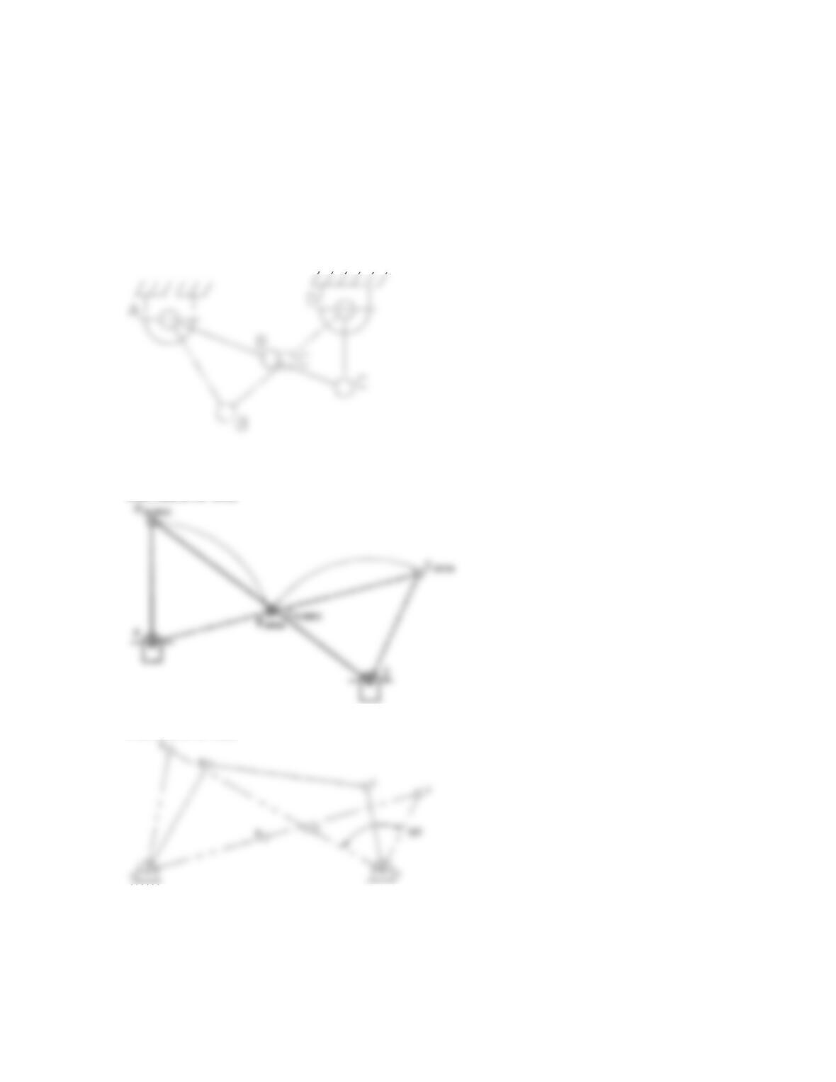
Linkage Problems
Part 1: Problems 16.1 Through 16.14
PROBLEM 16.1
PROBLEM 16.2
PROBLEM 16.3
290
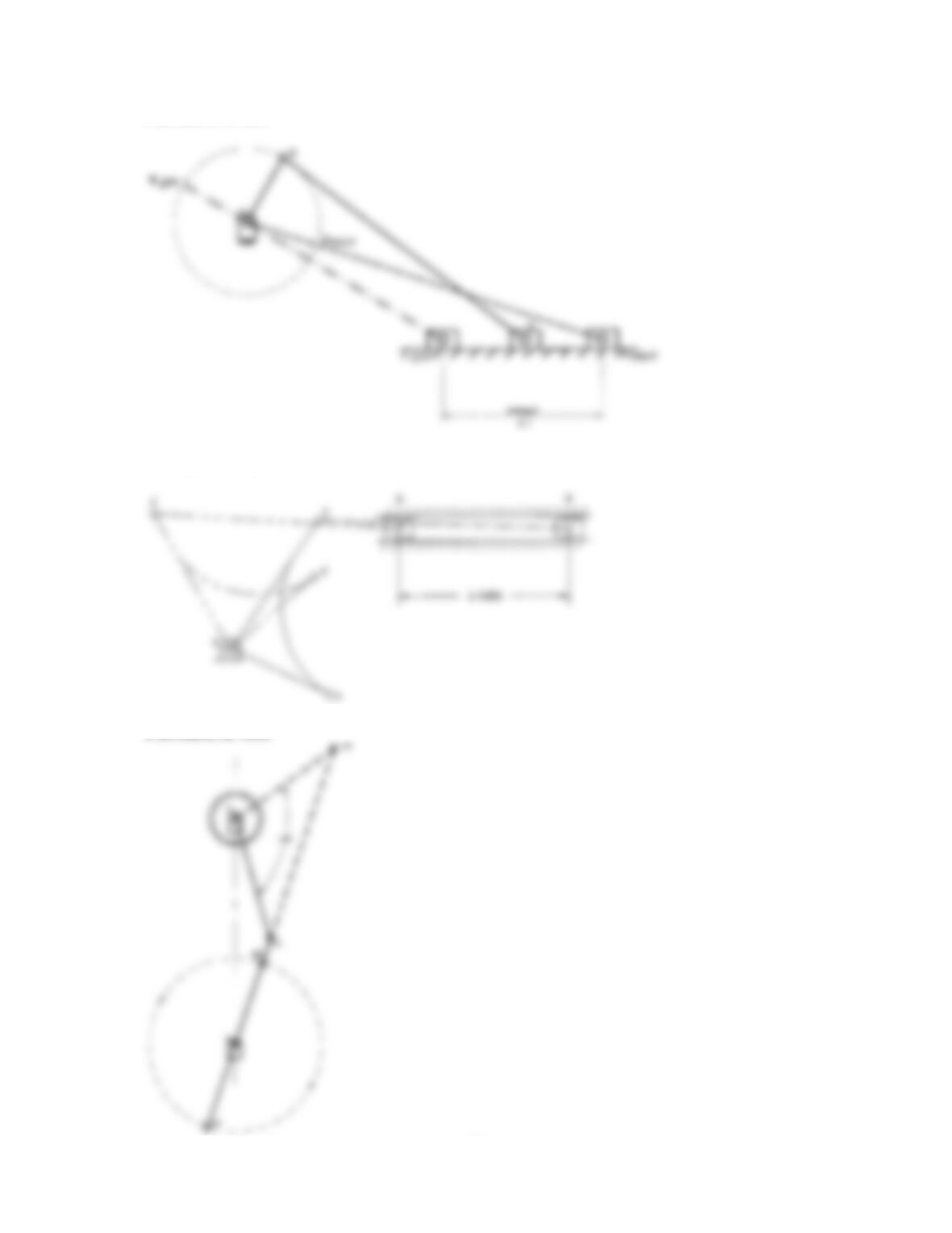
PROBLEM 16.4
PROBLEM 16.5
PROBLEM 16.6
291
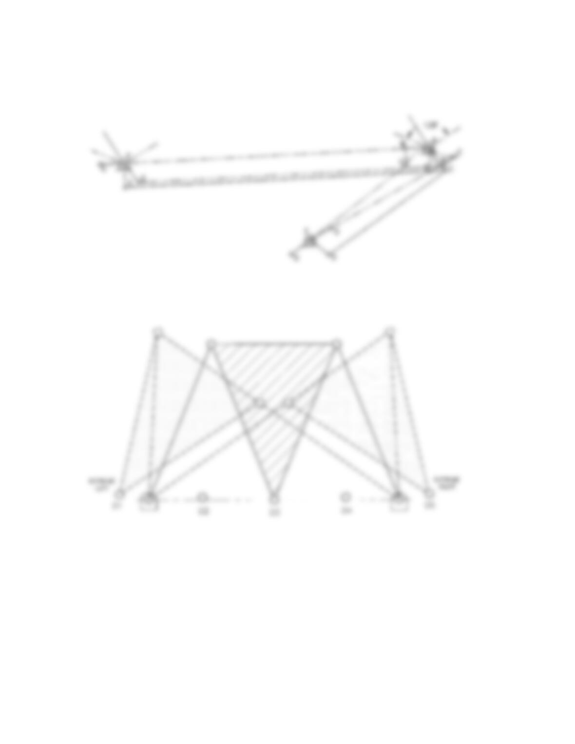
PROBLEM 16.7
PROBLEM 16.8
292
PROBLEM 16.10
293
PROBLEM 16.11
PROBLEM 16.12
294
PROBLEM 16.13
PROBLEM 16.14 Solutions will vary.
Cam Displacement Diagrams
Part 2: Problems 16.15 Through 16.25
PROBLEM 16.15
295
PROBLEM 16.16
PROBLEM 16.17
PROBLEM 16.18