
CHAPTER 15 WORKING DRAWINGS
PROBLEMS
INSTRUCTIONS
1. From the given engineering sketches or layouts, prepare a
complete set of working drawings, including details assembly
and parts list. Use appropriately sized standard ASME sheets
with border and sheet blocks. Determine which views and
dimensions should be used to completely detail each part. In
addition, determine the views, parts list, dimensions, and
notes, if any, for the assembly drawing. Use ASME standards.
The complete set of working drawings should be prepared
with one detail drawing per sheet using multiview projection
and with the assembly drawing and parts list on one sheet
unless otherwise specified. All purchase (standard) parts are
completely identified in the parts list. Use the sketches or
layouts as a guide to draw original multiview drawings on
adequately sized sheets. Use drafting applications that you
have learned, such as auxiliary views and sectioning tech-
niques, as needed for each drawing. Add all necessary dimen-
sions and notes using unidirectional dimensioning. Many of
the problems are designed to be manufactured as projects in
the manufacturing (machine) technology department.
2. When using solid modeling software, create the solid model
using the given geometry and confirm the accuracy of the given
engineering information as you proceed. Consult with your
instructor or supervisor if you discover errors in the geometry
and revise the drawings as needed to make the geometry
59728_ch15_EOC_ptg01.indd 1 2/3/16 2:23 PM
2
accurate and confirm that parts fit together. Use your com-
pleted part solid models to develop fully dimensioned 2-D de-
tail drawings. Place a 3-D model in the upper-left corner of the
drawing for use as a visualization aid. Assemble the part models
and create a 2-D assembly drawing with a correlated parts list.
3. Include the following general notes at the lower left corner of
each sheet .5 in. (13 mm) each way from the corner border lines:
NOTES:
1. DIMENSIONING AND TOLERANCING PER ASME
Y14.5-2009.
2. REMOVE ALL BURRS AND SHARP EDGES.
Note number 2 does not normally apply to the assembly draw-
ings. Additional general notes may be required, depending on
the specifications of each individual assignment. Use the follow-
ing for tolerances for unspecified inch values. A tolerance block
is recommended as described in Chapter 2.
Unspecified Tolerances
Decimals In.
X6.1
XX 6.01
XXX 6.005
ANGULAR 6309
FINISH 125 μin.
For metric drawings, provide a general note that states TOLER–
ANCES FOR UNSPECIFIED DIMENSIONS COMPLY WITH ISO
2768-m. Provide a general note that states SURFACE FINISH
3.2 µm UNLESS OTHERWISE SPECIFIED.
choose, or if you are assigned to solve these advanced problems,
you should study Chapters 16, 17, and 18 as you encounter parts
in your problems that relate to content found in those chapters.
This is the kind of challenge that you can face in the real world of
engineering drafting. Often you have to go ahead on your own or
seek additional instruction when you encounter new and varied
obstacles. The following are the types of features that require you
to study additional content beyond this chapter:
■Linkages, cams, gears, and bearings in Chapter 16.
■Belt and chain drives in Chapter 17.
■Welding representations and assembly of welded parts in
Chapter 18.
Special Note: Some problems in this chapter contain errors,
missing information, or slight inaccuracies. This is intentional
and is meant to encourage you to apply appropriate problem-
solving methods, engineering, and drafting standards in order to
solve the problems. This is meant to force you to think about
each part and how parts fit together in the assembly. As in real-
world projects, the engineering problem should be considered as
a basis for your preliminary layouts. Always question inaccura-
cies in project designs and consult with the proper standards
and other sources. In some cases, an error might be the source of
engineering changes provided by your instructor, but this is de-
termined by your specific course objectives. Other situations re-
quire that corrections be made during the development of the
original design drawings. This is not intended as a source of
frustration but is considered part of an engineering drafter’s
daily responsibility in project development.
DRAFTING
TEMPLATES
To access CADD template files
with predefined drafting
settings, go to the Student
Companion Website, select
Student Downloads,
Drafting Templates and then
select the appropriate
template file. The ASME-Inch
and ASME-Metric drafting
templates follow ASME, ISO,
and related mechanical drafting
standards. Drawing templates
include standard sheet sizes
and formats and a variety of
appropriate drawing settings
and content. You can also use
a utility such as the AutoCAD
DesignCenter to add content
from the drawing templates to
your own drawings and
templates. Consult with your
instructor to determine which
template drawing and drawing
content to use.
NOTE: Each problem assignment is given as an
engineering layout to help simulate actual real-
world drafting conditions. Problems become
more complex as you continue.
Dimensions and views on engineer layouts may not beplaced
in accordance with acceptable standards. You need to carefully re-
view this chapter and previous chapter contents when preparing
the layout sketch. In some problems, the engineer layout assumes
certain information, such as the symmetry of a part or the align-
ment of holes. You need to place enough dimensions or draw lines
between features to fully dimension each part. In addition, evaluate
proper tolerancing between mating components to make sure they
fit during assembly. For example, a 1-in. shaft does not always fit in
a 1-in. hole, depending on the tolerance applied to thefeatures.
Most of the Chapter 15, Working Drawings, problems can be
drawn without studying other chapters in this section. However,
several of the given problems are advanced and challenging and
are best solved after you study all Section Four chapters. If you
59728_ch15_EOC_ptg01.indd 2 2/3/16 2:23 PM
3
BASIC THROUGH ADVANCED PROBLEMS
Part 1 : Problems 15.1 Through 15.22
PROBLEM 15.1 Working-drawing assembly (metric)
Assembly Name: Plumb Bob
SPECIFIC INSTRUCTIONS: Prepare a working-drawing assem-
bly that has a detail drawing of each part, an assembly drawing,
and a parts list on one sheet.
PARTS LIST
ITEM QTY NAME MATERIAL
1 1 PLUMB BOB BRONZE
2 1 CAP BRONZE
TWO PICTORIAL VIEWS OF
THE CAP ARE PROVIDED
FOR CLARITY
PROBLEM 15.2 Working drawing (in.)
Assembly Name: Hammer
SPECIFIC INSTRUCTIONS: Prepare a detail drawing for the
hammer head and two optional hammer handles on one sheet.
Make the assembly drawing and parts list on another sheet.
(a)
59728_ch15_EOC_ptg01.indd 3 2/3/16 2:23 PM
4
(c)
PROBLEM 15.2
(Continued)
(b)
59728_ch15_EOC_ptg01.indd 4 2/3/16 2:23 PM
5
PROBLEM 15.3 Working drawing (in.)
Assembly Name: Key Holder
SPECIFIC INSTRUCTIONS: Prepare a detail drawing for each
part, an assembly drawing, and a parts list on one sheet, unless
otherwise specified by your instructor.
59728_ch15_EOC_ptg01.indd 5 2/3/16 2:23 PM
6
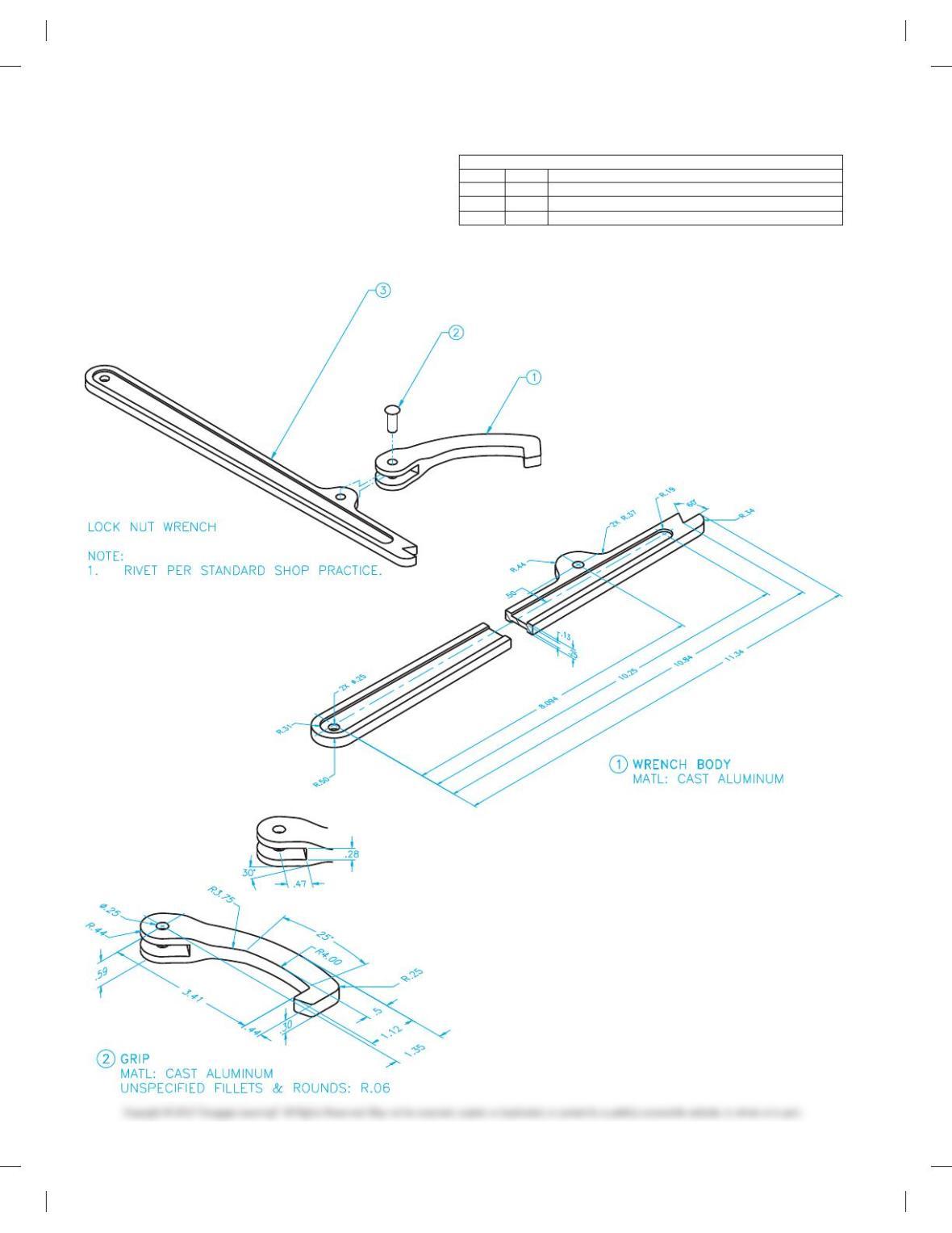
PROBLEM 15.4 Working drawing (in.)
Assembly Name: Lock Nut Wrench
SPECIFIC INSTRUCTIONS: Prepare a complete set of working
drawings with all of the detail drawings on one sheet and the as-
sembly drawing and bill of materials on another sheet. Use mul-
tiview projection for view layout.
LOCK NUT WRENCH BILL OF MATERIALS
ITEM QTY DESCRIPTION
1 1 GRIP
2 1
STEEL RIVET, Ø .25 X .625 LONG
3 1 MAIN BODY
59728_ch15_EOC_ptg01.indd 6 2/3/16 2:23 PM
7
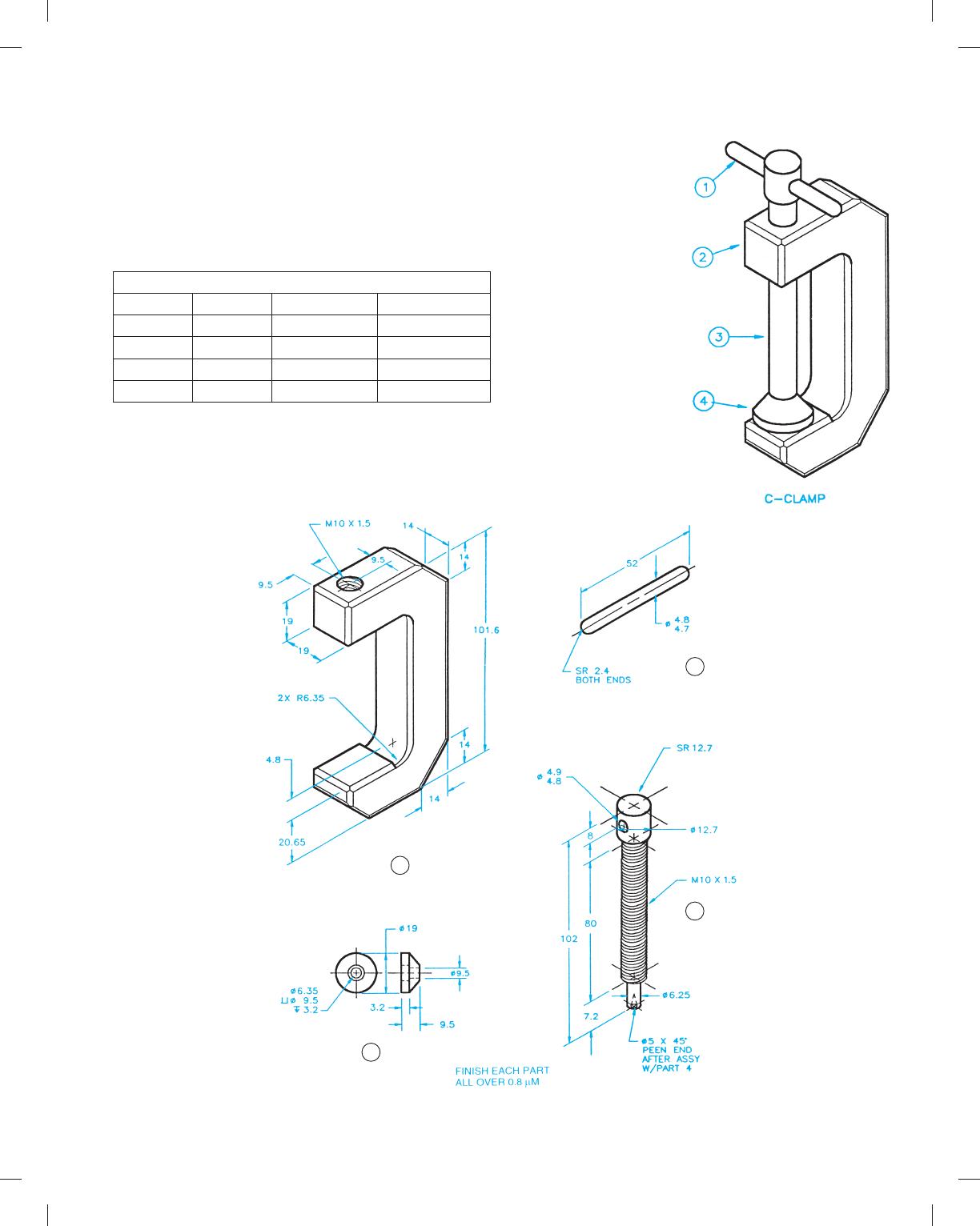
PROBLEM 15.5 Working drawing (metric)
Assembly Name: C-clamp
SPECIFIC INSTRUCTIONS: Prepare a complete set of working
drawings with all of the detail drawings on one sheet and the as-
sembly drawings and parts list on another sheet. Use multiview
projection for view layout.
PARTS LIST
ITEM QTY NAME MATERIAL
1 1 PIN CRMS
2 1 BODY SAE 4320
3 1 SCREW SAE 4320
4 1 SWIVEL SAE 1020
C-CLAMP
1 PIN
2 BODY
CHAMFER ALL CORNER 45˚ X 1.6
4 SWIVEL
3 SCREW
59728_ch15_EOC_ptg01.indd 7 2/3/16 2:23 PM
8
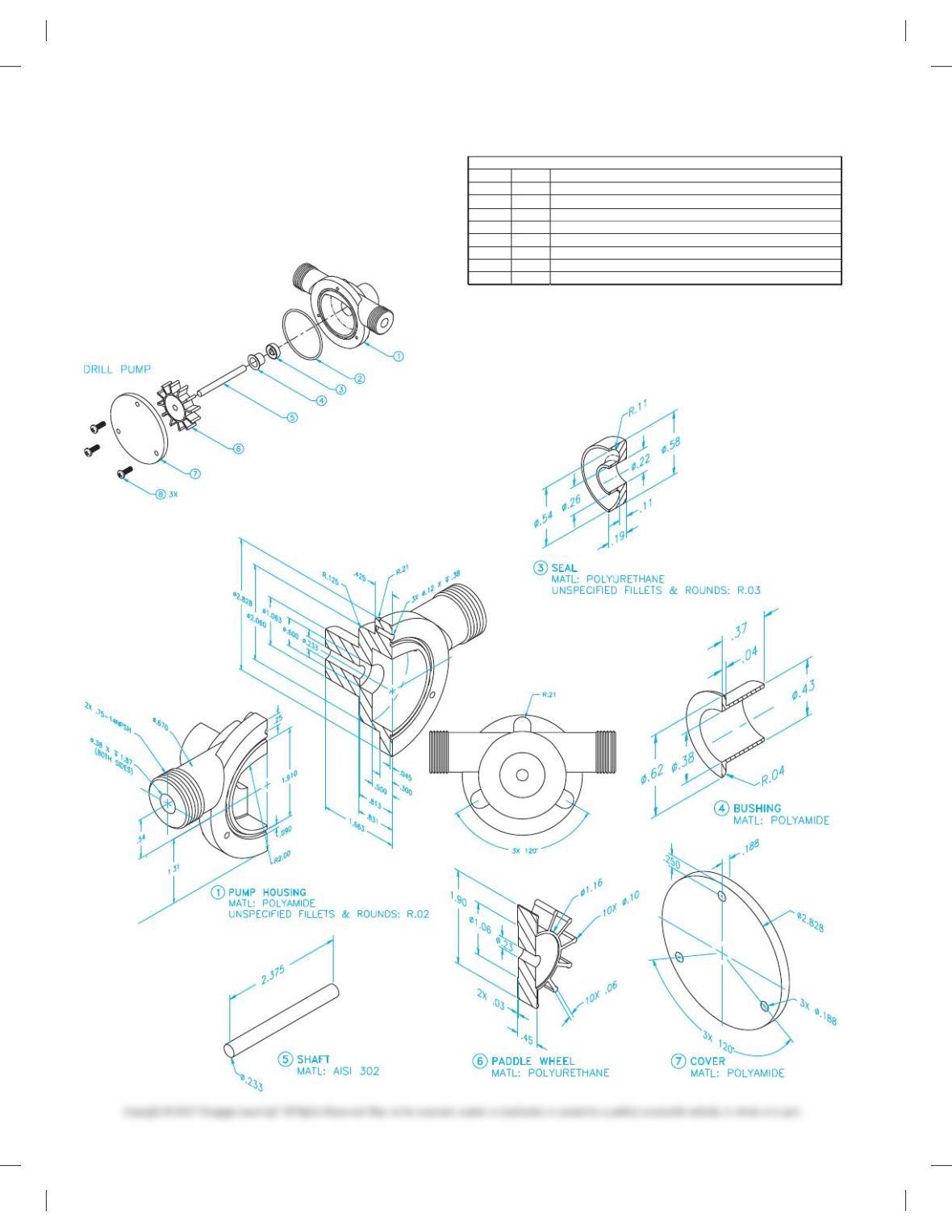
PROBLEM 15.6 Working drawing (in.)
Assembly Name: Drill Pump
SPECIFIC INSTRUCTIONS: Prepare a complete set of working
drawings with one detail drawing per sheet and the assembly
drawing and bill of materials on another sheet. Use multiview
projection for view layout.
DRILL PUMP BILL OF MATERIALS
ITEM QTY DESCRIPTION
1 1 PUMP HOUSING
2 1
.070 O-RING, Ø 2.00
3 1 SEAL
4 1 PLASTIC BUSHING
5 1 SHAFT
6 1 PADDLE WHEEL
7 1 COVER
8 3 1/8” X 5/8” LONG PAN HEAD SCREW, THREAD CUTTING
59728_ch15_EOC_ptg01.indd 8 2/3/16 2:23 PM
9
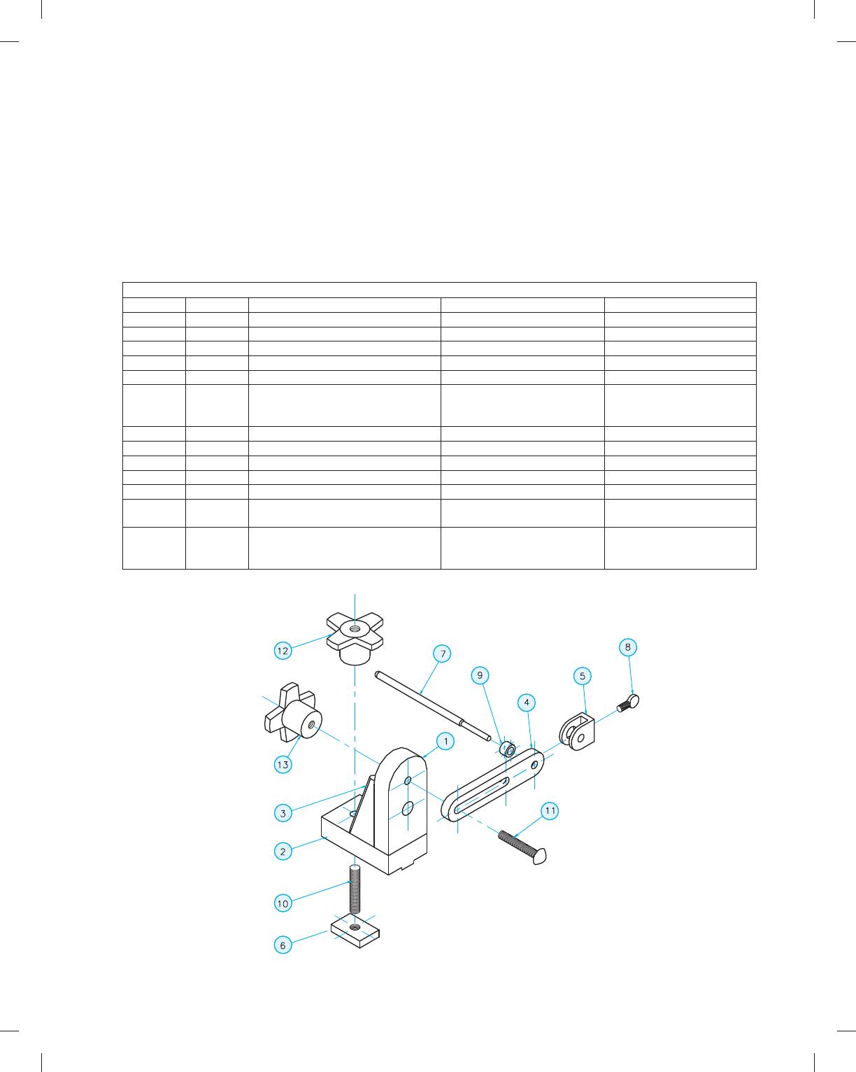
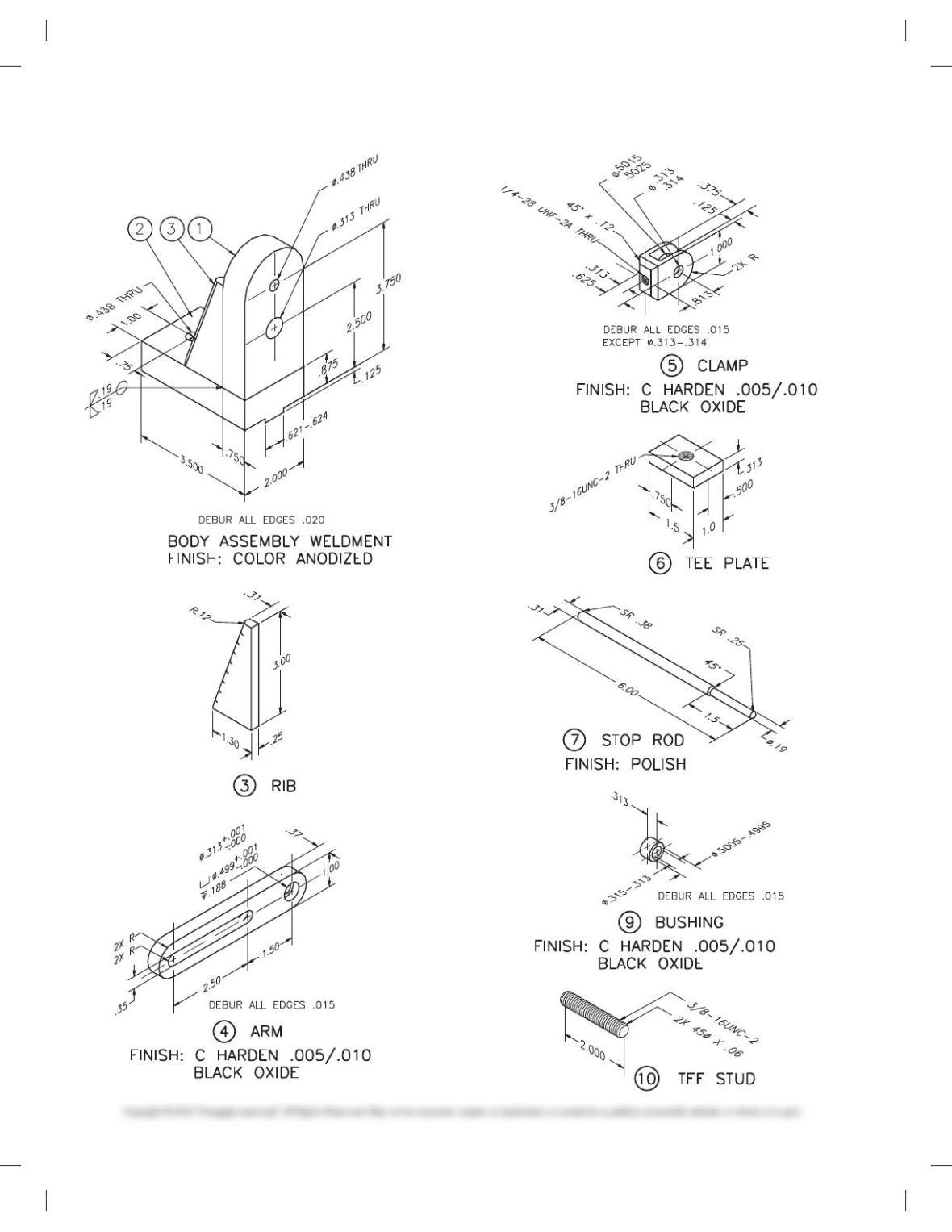
PROBLEM 15.7 Working drawing (in.)
Assembly Name: Mill Work Stop
SPECIFIC INSTRUCTIONS: This problem has basic applications.
However, there is a welding symbol involved in the assembly. You
should study welding processes and representations covered in
Chapter 18 before completing this problem.
Prepare a complete set of working drawings with one detail
drawing per sheet and the assembly drawing with parts list on
one sheet. Notice that part number 10, TEE STUD, is cut from
standard 3/8-16UNC ALL THREAD. Parts 12 and 13, BLANK
KNOBS, are purchased as knobs without the threads machined.
You will draw the knobs as a representation of the purchase part
and give the thread note as identified in the parts list. The actual
dimensions of the knob to be purchased are not important. How-
ever, accurate specifications for the threads to be machined into
the purchase part are important. Note: Some design is required
throughout the completion of the project.
PARTS LIST
ITEM QTY NAME DESCRIPTION MATERIAL
1 1 VERTICAL MEMBER 3/4 3 2 3 4 SAE 6061
2 1 BASE MEMBER 1 3 2 3 3.5 SAE 6061
3 2 RIB 1/4 PLATE SAE 6061
4 1 ARM 3/8 3 1 3 5-1/2 SAE 1018
5 1 CLAMP 1/2 3 1 3 1-5/16 SAE 1018
6 1 TEE PLATE DRILL AND
TAP AT CENTER FOR
5/16-18UNC-2 THREAD THRU
5/16 3 1 3 1-1/4 SAE 1018
7 1 STOP ROD Ø5/16 3 6 SAE 303 SS
8 1 WING NUT 1/4-28 3 1/2
9 1 BUSHING Ø1/2 3 .31 SAE 1018
10 1 TEE STUD 3/8-16 3 2 LG ALL THREAD
11 1 CARRIAGE BOLT 5/16-18UNC-2
12 21 BLANK KNOB VLIER HK-3 (DRILL AND
TAP FOR 3/8-16UNC-2B)
13 1 BLANK KNOB VLIER HK-3
(DRILL AND TAP FOR
5/16-18UNC-2B)
59728_ch15_EOC_ptg01.indd 9 2/3/16 2:23 PM
10
PROBLEM 15.7
(Continued)
59728_ch15_EOC_ptg01.indd 10 2/3/16 2:24 PM
11
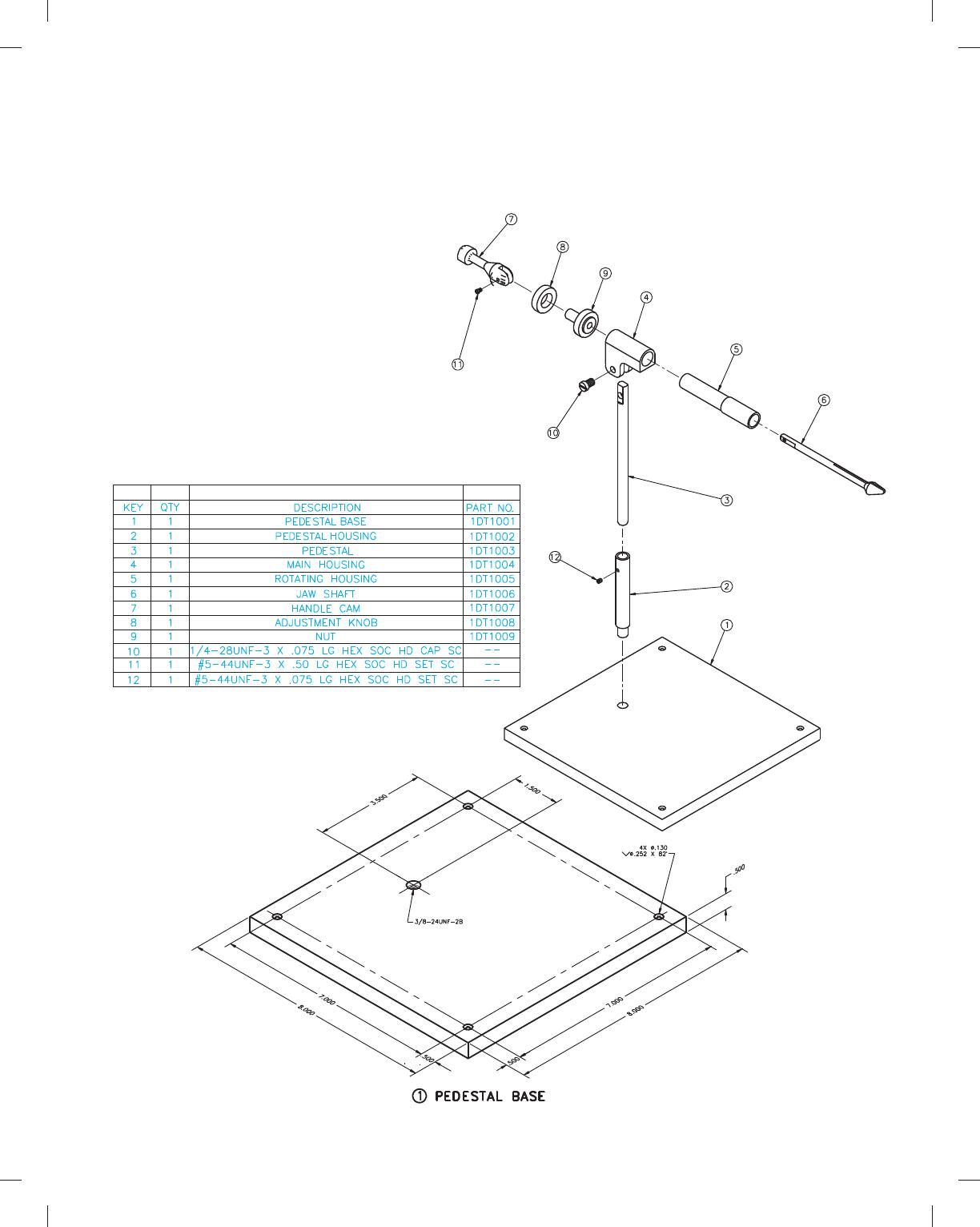
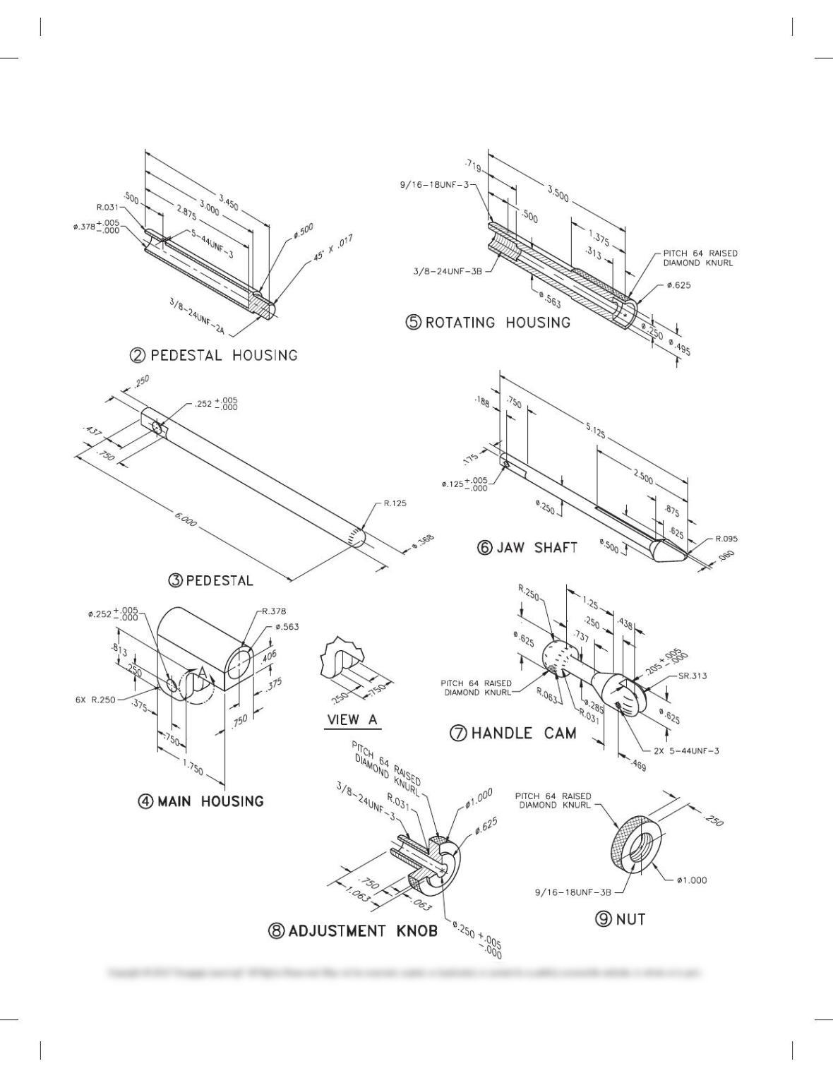
PROBLEM 15.8 Working drawing (in.)
Assembly Name: Fly Tying Vise
SPECIFIC INSTRUCTIONS: Prepare a complete set of working
drawings with one detail drawing per sheet and the assembly
PARTS LIST
and parts list on another sheet. When preparing the assembly
drawing, use separate balloons for each part in each view or use
only one balloon in the view that most clearly identifies the part.
Problem Courtesy of David P. Madsen and John Melloy.
59728_ch15_EOC_ptg01.indd 11 2/3/16 2:24 PM
12
PROBLEM 15.8
(Continued)
59728_ch15_EOC_ptg01.indd 12 2/3/16 2:24 PM
13
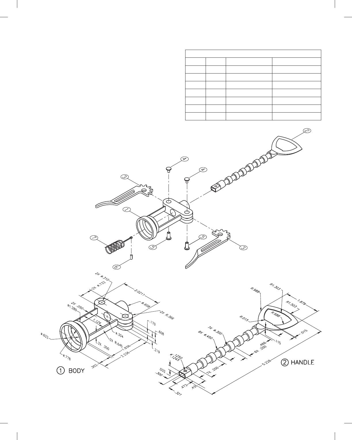
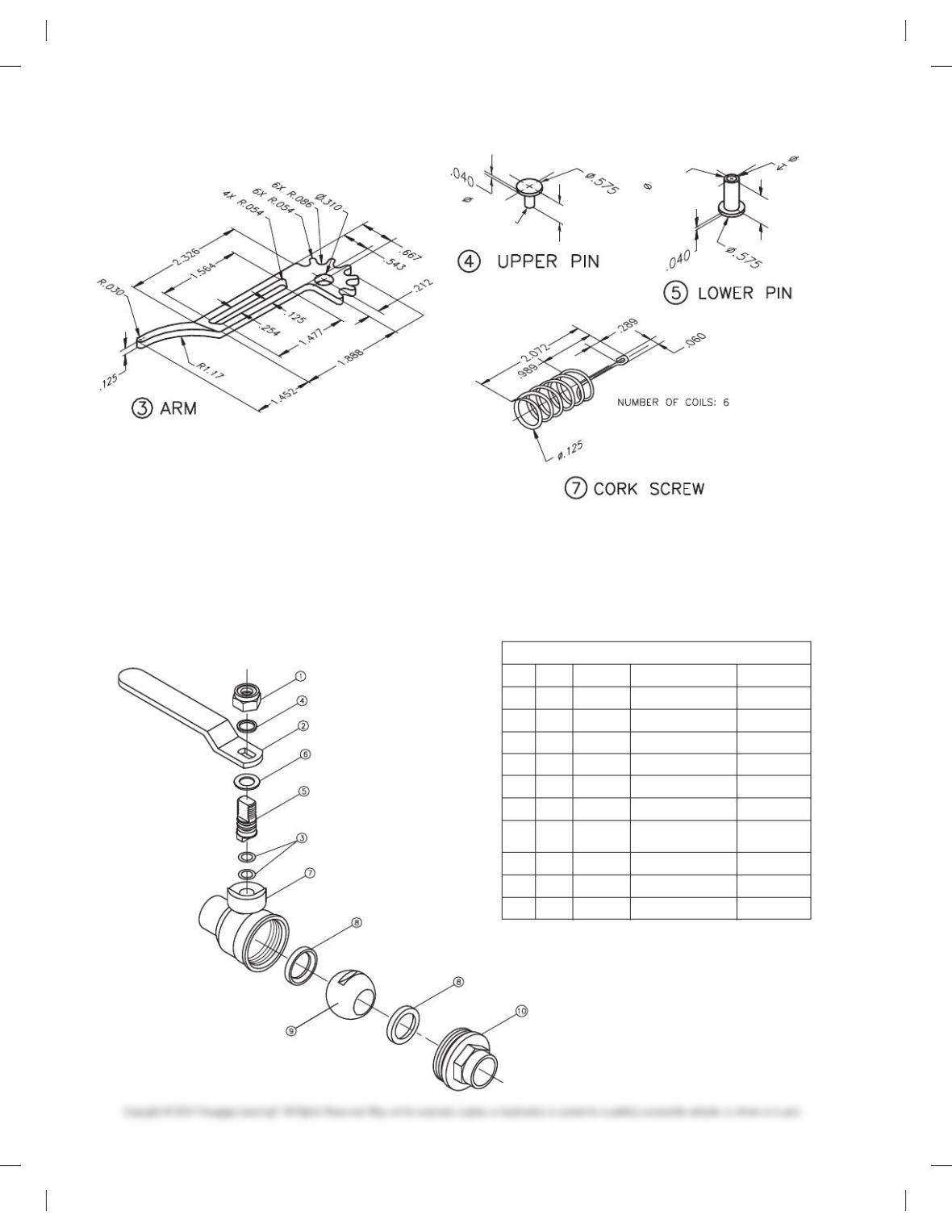
PROBLEM 15.9 Working drawing (in.)
Assembly Name: Cork Screw
SPECIFIC INSTRUCTIONS: Prepare a complete set of working
drawings with one detail drawing per sheet and the assembly
and parts list on another sheet. When preparing the assembly
drawing, use separate balloons for each part in each view or use
only one balloon in the view that most clearly identifies the part.
Establish tolerances between mating parts. Determine the di-
mensions for the Pin, Part 6 and create needed detail or purchase
part specifications. Errors are likely in this problem. Identify and
correct errors as discussed in the general problem instructions
in this chapter. Verify dimensions during assembly. Establish
tolerances between mating parts.
PARTS LIST
ITEM QTY NAME MATERIAL
1 1 BODY Stainless Steel
2 1 HANDLE Stainless Steel
3 2 ARM Stainless Steel
4 2 UPPER PIN Stainless Steel
5 2 LOWER PIN Stainless Steel
6 1 PIN Stainless Steel
7 1 CORK SCREW Stainless Steel
59728_ch15_EOC_ptg01.indd 13 2/3/16 2:24 PM
14
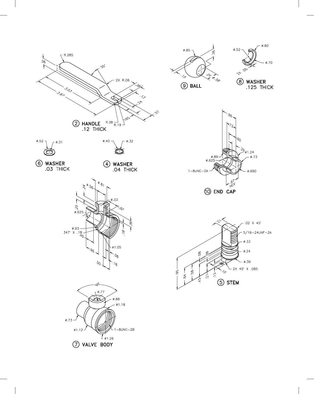
PROBLEM 15.10 Working drawing (in.)
Assembly Name: Ball Valve
SPECIFIC INSTRUCTIONS: Prepare a complete set of working
drawings with one detail drawing per sheet and the assembly
and parts list on another sheet. When preparing the assembly
drawing, use separate balloons for each part in each view or use
.1295
.1290
.600
.1300
.1295
.500
.595
.300
.295
5 1 STEM STAINLESS STEEL 1DT1005
4 1 WASHER PLASTIC 1DT1004
3 2 O-RING PARKER #2-008 5DT1003
2 1 HANDLE STAINLESS STEEL 1DT1002
1 1 NUT 5/16-24UNF-2 5DT1001
KEY QTY NAME MATERIAL PART NO.
PARTS LIST
BODY
10 1 END CAP BRASS 1DT1010
9 1 BALL STAINLESS STEEL 1DT1009
8 2 WASHER PLASTIC 1DT1008
7 1 VALVE BRASS 1DT1007
6 1 WASHER PLASTIC 1DT1006
only one balloon in the view that most clearly identifies the part.
This is a prototype project. Errors are likely in this problem. Iden-
tify and correct errors as discussed in the general problem in-
structions in this chapter. Verify dimensions during assembly.
Establish tolerances between mating parts.
PROBLEM 15.9
(Continued)
59728_ch15_EOC_ptg01.indd 14 2/3/16 2:24 PM
15
PROBLEM 15.10
(Continued)
59728_ch15_EOC_ptg01.indd 15 2/3/16 2:24 PM
16
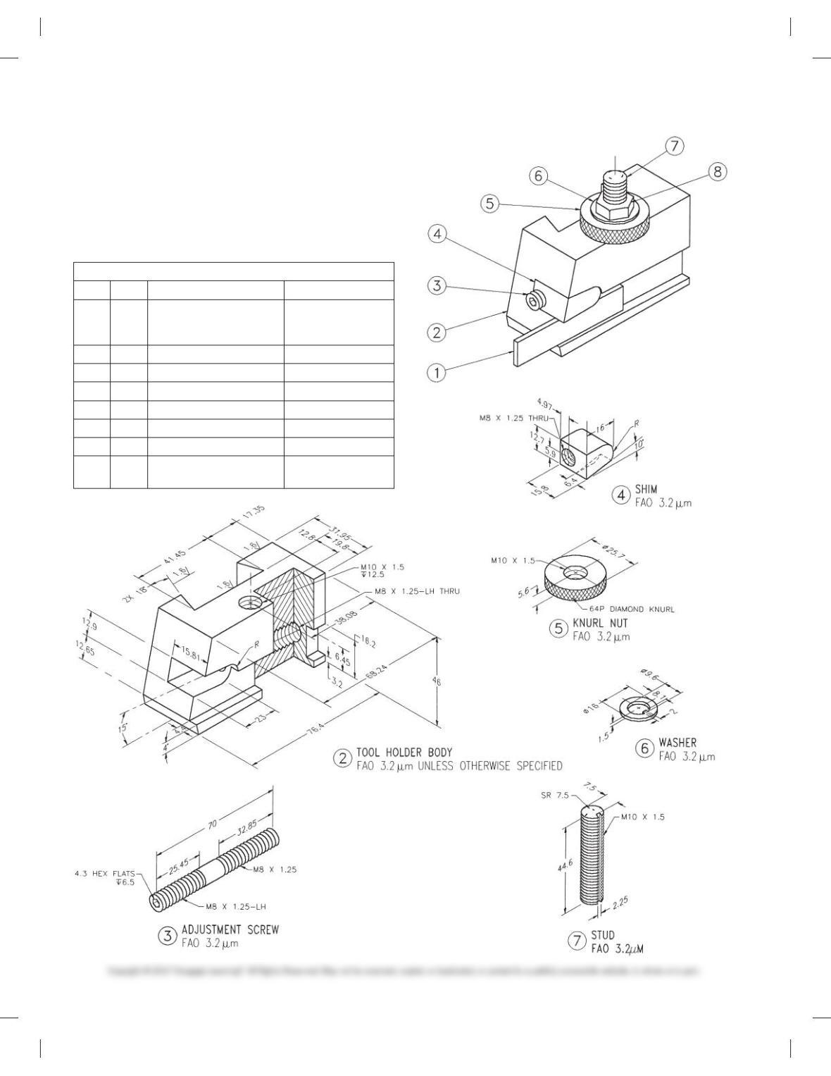
PROBLEM 15.11 Working drawing (metric)
Assembly Name: Tool Holder
SPECIFIC INSTRUCTIONS: Prepare a complete set of working
drawings with one detail drawing per sheet and the assembly
and parts list on another sheet. When preparing the assembly
drawing, use separate balloons for each part in each view or use
only one balloon in the view that most clearly identifies the part.
PARTS LIST
ITEM QTY NAME Material
1 1 PARTING TOOL,
3/32 IN 3 1/2 IN
PURCHASE PART
TOOL STEEL
2 1 TOOL HOLDER BODY 06 STEEL
3 1 ADJUSTMENT SCREW SAE 1035 STEEL
4 1 SHIM SAE 4320 STEEL
5 1 KNURL NUT SAE 3130 STEEL
6 1 WASHER SAE 1060 STEEL
7 1 STUD SAE 1035 STEEL
81 M 10 3 1.5 HEX NUT
PURCHASE PART
59728_ch15_EOC_ptg01.indd 16 2/3/16 2:24 PM
17
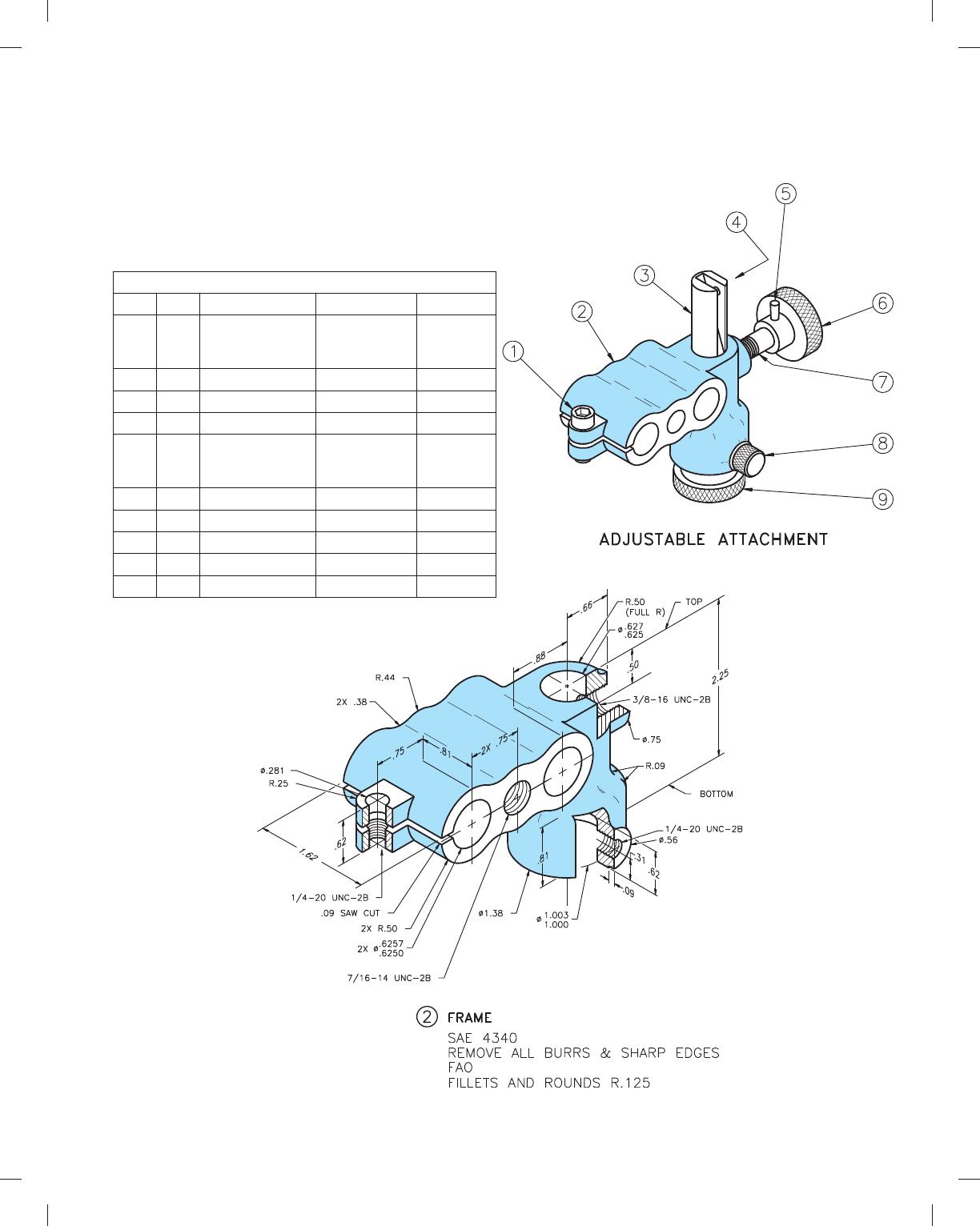
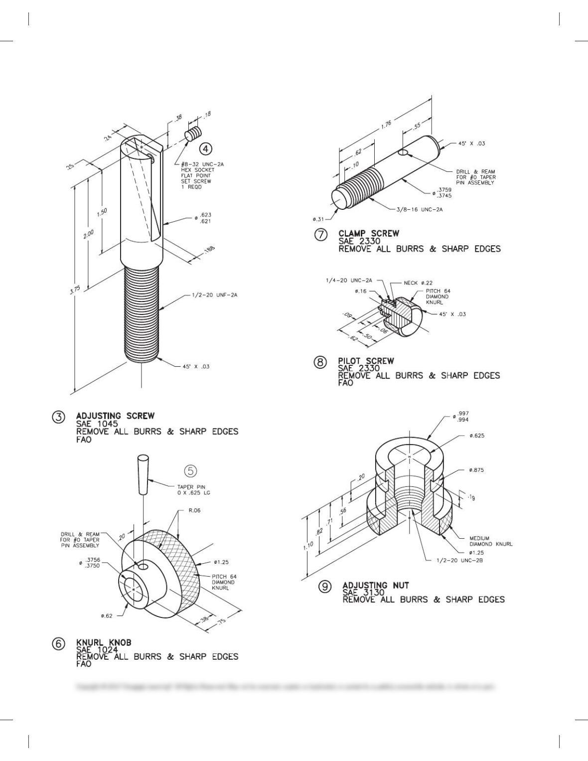
PROBLEM 15.12 Working drawing (in.)
Assembly Name: Adjustable Attachment
SPECIFIC INSTRUCTIONS: Prepare a complete set of working
drawings with detail drawings of individual parts combined on
one or more sheets, depending on the size of sheet selected. The
assembly drawing and parts list is combined on one sheet.
PARTS LIST
ITEM QTY NAME DESCRIPTION MATERIAL
1 1 CAP SCREW .25-20UNC-2 3
.75 HEX SOC
HEAD
STL
2 1 FRAME SAE 4340
3 1 ADJUSTING SAE1045
SCREW
4 1 SET SCREW 8-32UNC-2
HEX SOC FLAT
POINT
STL
5 1 TAPER PIN 0 3 .625 STL
6 1 KNURL KNOB SAE 1024
7 1 CLAMP SCREW SAE 2330
8 1 PILOT SCREW SAE 2330
9 1 ADJUSTING NUT SAE 3130
59728_ch15_EOC_ptg01.indd 17 2/3/16 2:24 PM
18
PROBLEM 15.12
(Continued)
59728_ch15_EOC_ptg01.indd 18 2/3/16 2:24 PM
19
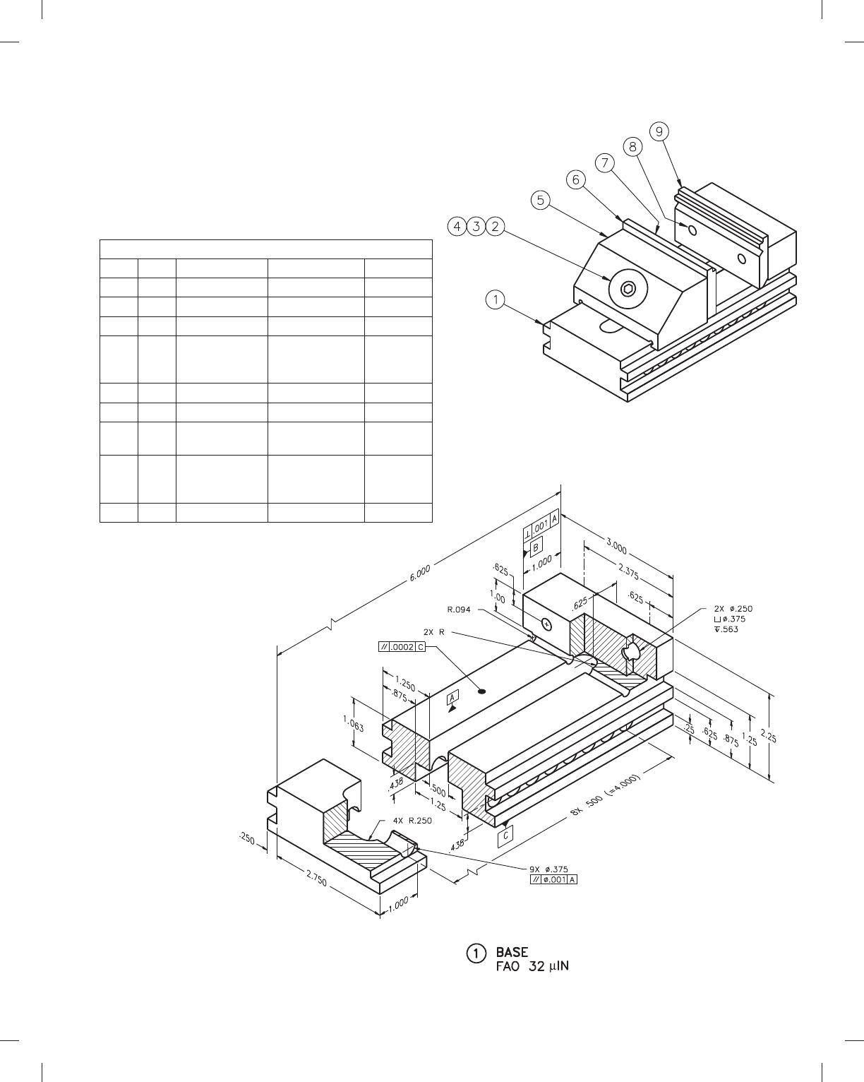
PROBLEM 15.13 Working drawing (in.)
Assembly Name: Precision Vise
SPECIFIC INSTRUCTIONS: Prepare a complete set of working
drawings with one detail drawing per sheet and the assembly
drawing and bill of materials on another sheet. Use multiview
projection for view layout.
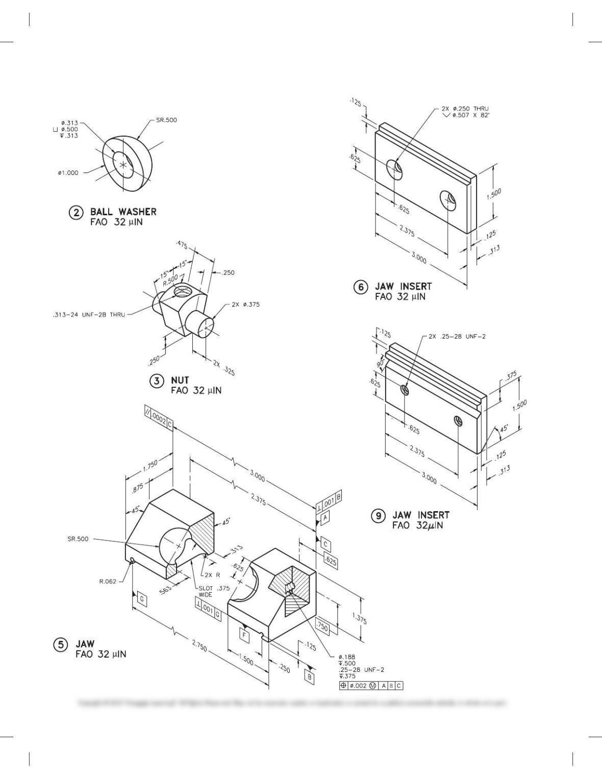
PARTS LIST
ITEM QTY NAME DESCRIPTION MATERIAL
1 1 BASE SAE 1040
2 1 BALL WASHER SAE 1040
3 1 NUT SAE 1040
4 1 CAP SCREW
5/16-24NF 3 1
1/2 HEX
SOCKET HEAD
STL
5 1 JAW SAE 1040
6 1 JAW INSERT SAE 4330
7 2 MACH SCREW
1/4-28NF 3 1/2
FLAT HD
STL
8 2 CAP SCREW
1/4-28NF 3 3/4
HEX SOCKET
HEAD
STL
9 1 JAW INSERT SAE 4330
TWO SURFACES
59728_ch15_EOC_ptg01.indd 19 2/3/16 2:24 PM
20
PROBLEM 15.13
(Continued)
59728_ch15_EOC_ptg01.indd 20 2/3/16 2:24 PM