21
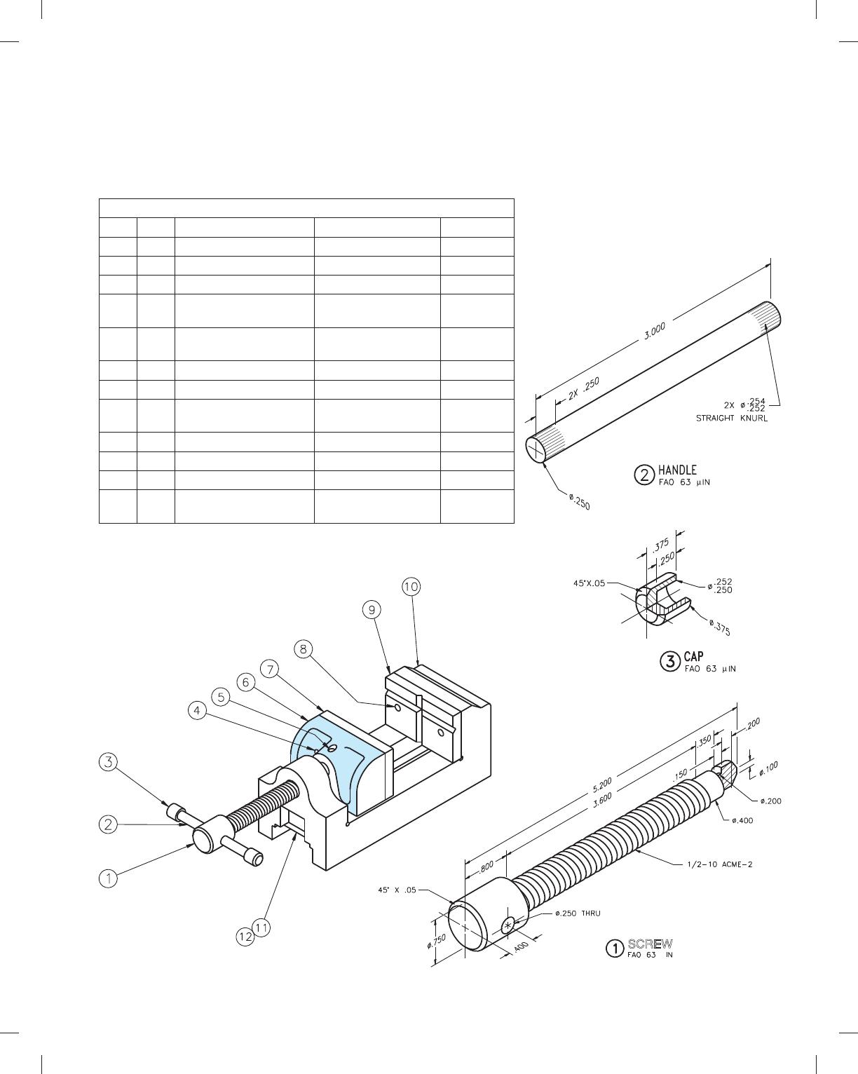
PROBLEM 15.14 Working drawing (in.)
Assembly Name: Machine Vise
SPECIFIC INSTRUCTIONS: When preparing the assembly draw-
ings, use separate balloons for each part in each view or use only
one balloon in the view that most clearly identifies the part.
Prepare a complete set of working drawings with one detail
drawing per sheet and the assembly drawing and bill of materials
on another sheet. Use multiview projection for view layout.
PARTS LIST
ITEM QTY NAME DESCRIPTION MATERIAL
1 1 SCREW SAE 4320
2 1 HANDLE MS
3 2 CAP MS
4 2 MACHINE SCREW (10).190-32UNF-2 3
.625 SLOT FIL HD
STL
5 1 SET SCREW 1/4-20UNC-2 3 .250
FULL DOG POINT
STL
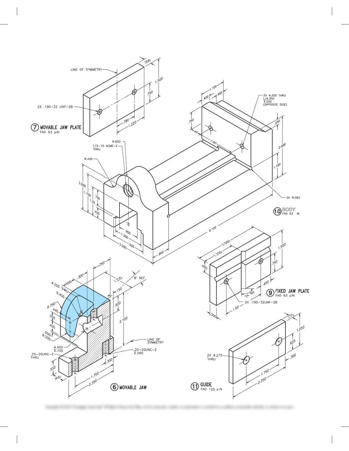
6 1 MOVABLE JAW SAE 1020
7 1 MOVABLE JAW PLATE SAE 4320
8 2 MACHINE SCREW (10).190-32UNF-2 3
.875 SLOT FIL HD
STL
9 1 FIXED JAW PLATE SAE 4320
10 1 BODY SAE 4320
11 1 GUIDE SAE 1020
12 2 MACHINE SCREW 1/4-20UNC-2 3 .500
SLOT FIL HD
STL
SCREW
59728_ch15_EOC_ptg01.indd 21 2/3/16 2:24 PM
22
BODY
PROBLEM 15.14
(Continued)
59728_ch15_EOC_ptg01.indd 22 2/3/16 2:24 PM
23
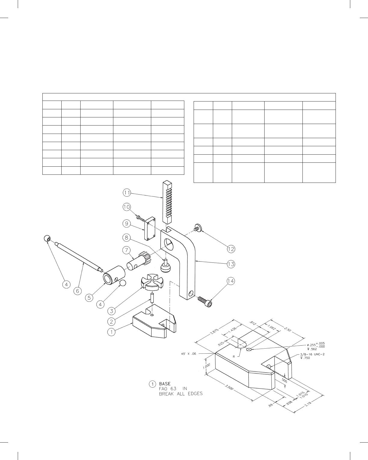
PROBLEM 15.15 Working drawing (in.)
Assembly Name: Arbor Press
SPECIFIC INSTRUCTIONS: This problem is generally basic, but
it also contains challenging applications that include gears. You
should study gears and related drafting practices covered in
Chapter 16 before completing this problem. Prepare a complete
set of working drawings with one detail drawing per sheet and
the assembly drawing and bill of materials on another sheet. Use
multiview projection for view layout.
µ
ITEM QTY NAME DESCRIPTION MATERIAL
1 1 BASE SAE 1020
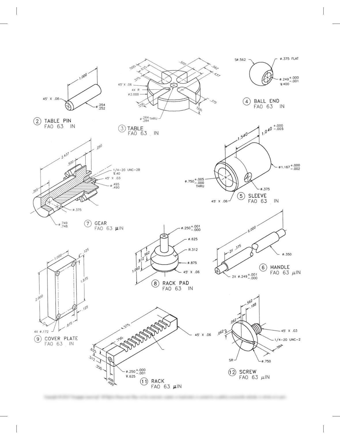
2 1 TABLE PIN SAE 1020
3 1 TABLE SAE 1020
4 2 BALL END SAE 1020
5 1 SLEEVE SAE 1020
6 1 HANDLE SAE 1020
7 1 GEAR SAE 4320
8 1 RACK PAD SAE 4320
ITEM QTY NAME DESCRIPTION MATERIAL
9 1 COVER
PLATE
SAE 1020
10 4 CAP
SCREWS
8-32UNC-2 3
.50 HEX SOC
STL
11 1 RACK SAE 4320
12 1 SCREW SAE 1040
13 1 COLUMN SAE 1020
14 1 CAP SCREW 3/8-16UNC-2 3
1.00 HEX
SOCKET HEAD
STL
PARTS LIST
59728_ch15_EOC_ptg01.indd 23 2/3/16 2:24 PM
24
m
m
m
m
DIAMETRAL PITCH 12
NUMBER OF TEETH 12
OUTSIDE DIAMETER 1.164
PRESSURE ANGLE 208
m
m
TOOTH THICKNESS
AT PITCH LINE .1309
PRESSURE ANGLE 208
LINEAR PITCH .262
DIAMETRAL PITCH 12
NUMBER OF TEETH 12
LINEAR PITCH .262
WHOLE DEPTH .183
WORKING DEPTH .166
m
m
PROBLEM 15.15
(Continued)
59728_ch15_EOC_ptg01.indd 24 2/3/16 2:24 PM
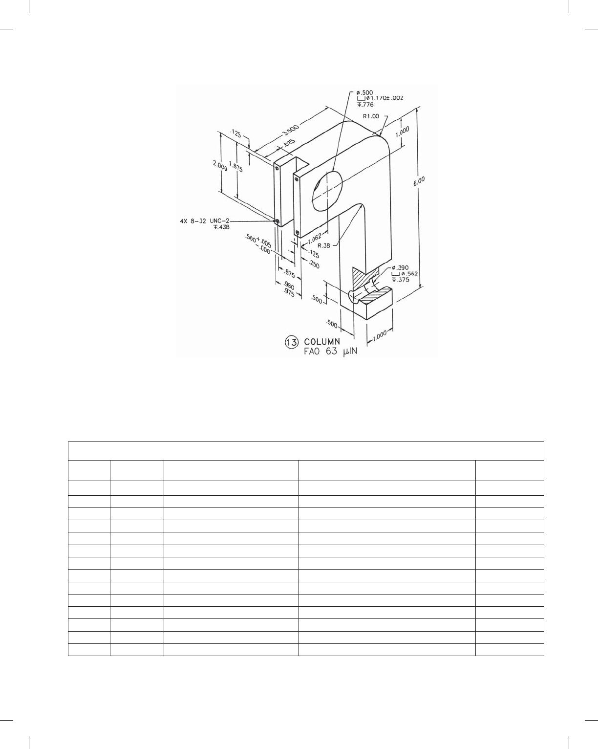
25
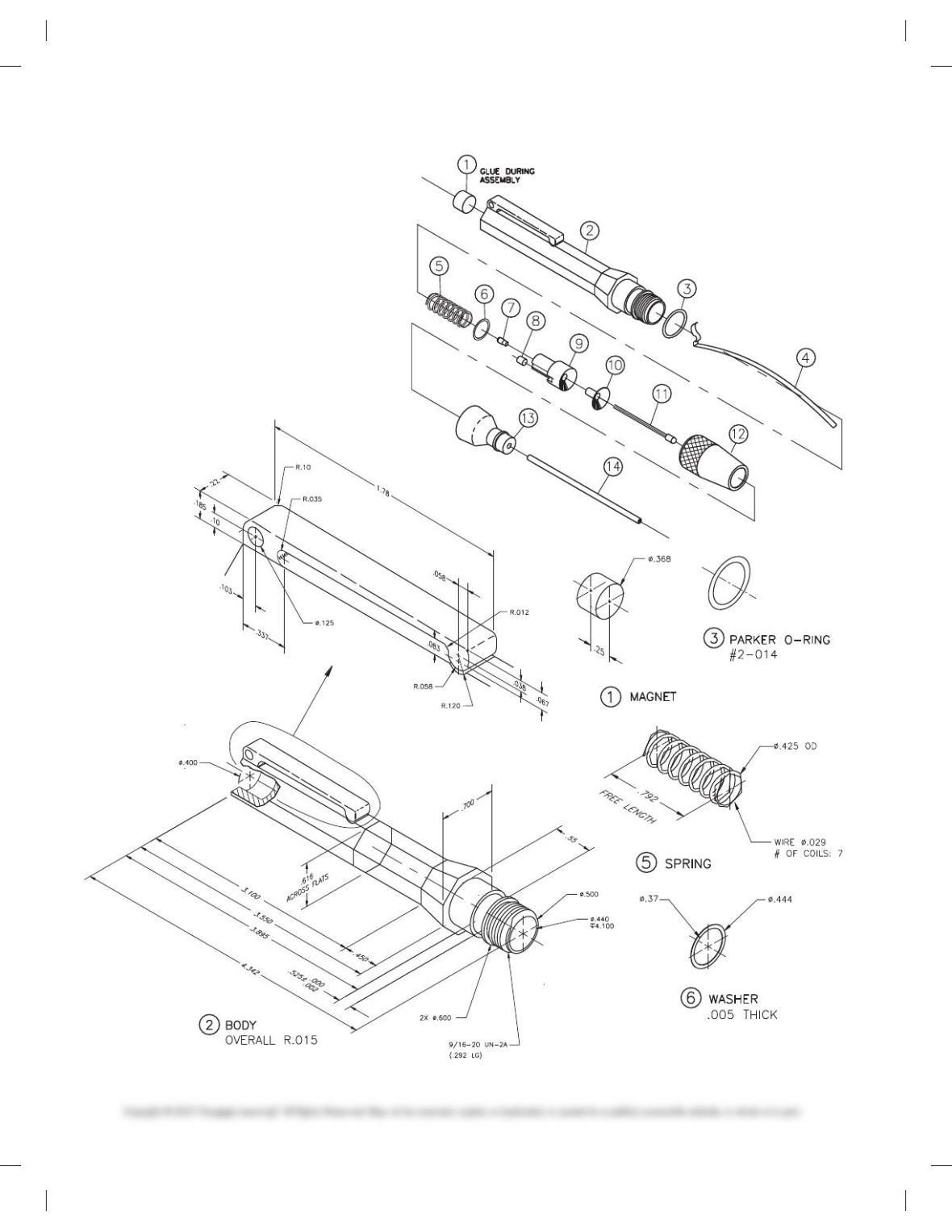
PROBLEM 15.16 Working drawing (in.)
Assembly Name: Pen Light
SPECIFIC INSTRUCTIONS: Prepare a complete set of working
drawings with one detail drawing per sheet and the assembly
and parts list on another sheet. When preparing the assembly
drawing, use separate balloons for each part in each view or use
only one balloon in the view that most clearly identifies the part.
This is an engineering prototype project. Errors are likely. Verify
dimensions during assembly. Establish tolerances between
mating parts.
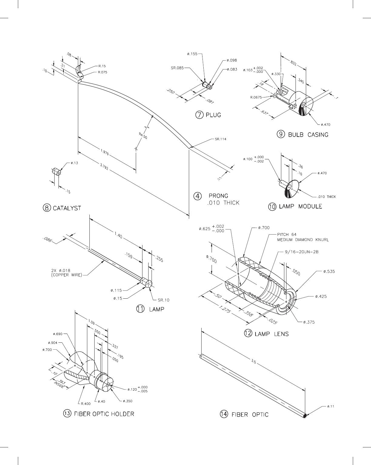
14 1 FIBER OPTIC FIBER-OPTIC 3-1/2” 3 ?12” 5DT1014
13 1 FIBER OPTIC HOLDER (PVF) POLYVINYLIDENE FLOURIDE 1DT1013
12 1 LAMP LENS POLYCARBONATE 1DT1012
11 1 LAMP HIGH INTENSITY XENON 5DT1011
10 1 LAMP MODULE VACUUM METALLIZED 1DT1010
9 1 BULB CASING POLYCARBONATE 1DT1009
8 1 CATALYST DE OXO TYPE D 5DT1008
7 1 PLUG PHOSPHOR BRONZE 1DT1007
6 1 WASHER PHOSPHOR BRONZE 1DT1006
5 1 SPRING PHOSPHOR BRONZE 1DT1005
4 1 PRONG PHOSPHOR BRONZE 1DT1004
3 1 PARKER O-RING PARKER #2-014 5DT1003
2 1 BODY POLYCARBONATE 1DT1002
1 1 MAGNET MAGNET 5DT1001
KEY QTY NAME DESCRIPTION PART NO.
PARTS LIST
PROBLEM 15.15
(Continued )
59728_ch15_EOC_ptg01.indd 25 2/3/16 2:24 PM
26
PROBLEM 15.16
(Continued)
59728_ch15_EOC_ptg01.indd 26 2/3/16 2:24 PM
27
PROBLEM 15.16
(Continued)
59728_ch15_EOC_ptg01.indd 27 2/3/16 2:24 PM
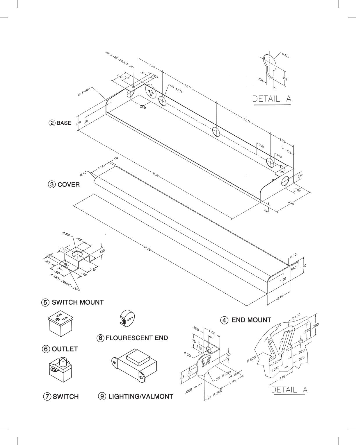
28
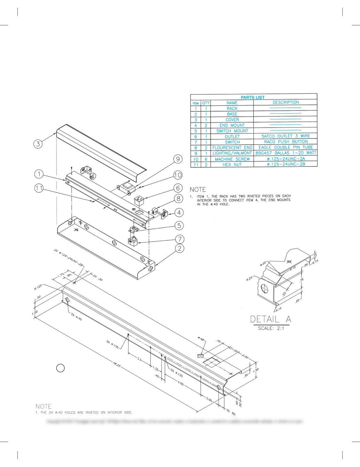
PROBLEM 15.17 Working drawing (in.)
Assembly Name: Fluorescent Light Fixture
SPECIFIC INSTRUCTIONS: Prepare a complete set of working
drawings with one detail drawing per sheet and the assembly and
parts list on another sheet. When preparing the assembly drawing,
use separate balloons for each part in each view or use only one
:
balloon in the view that most clearly identifies the part. This is an
engineering prototype project. Errors are likely in this problem.
Verify dimensions during assembly. Establish tolerances between
mating parts. There are several purchase parts in this assembly.
Manufacturer research is needed to locate available products.
1 RACK
:
59728_ch15_EOC_ptg01.indd 28 2/3/16 2:24 PM
29
PROBLEM 15.17
(Continued)
59728_ch15_EOC_ptg01.indd 29 2/3/16 2:24 PM
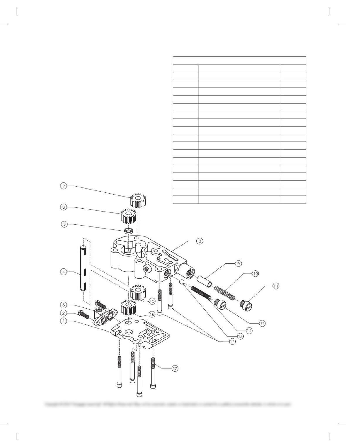
30
PROBLEM 15.18 Working drawing (in.)
Assembly Name: Oil Pump
SPECIFIC INSTRUCTIONS: This problem is challenging, and
contains applications that include gears and seals. You should
study gears and related drafting practices covered in Chapter 16
Mechanisms: Linkages, Cams, Gears, and Bearings before com-
pleting this problem.
Prepare a complete set of working drawings with one detail
drawing per sheet and the assembly and parts list on another
sheet. When preparing the assembly drawing, use separate bal-
loons for each part in each view or use only one balloon in the
view that most clearly identifies the part. This is an engineering
prototype project. Errors are likely in this problem. Verify dimen-
sions during assembly. Establish tolerances between mating
parts. There are several purchase parts in this assembly. Manu-
facturer research is needed to locate available products.
PARTS LIST
ITEM DESCRIPTION QTY
1 PUMP COVER 1
21/4 – 20 3 3/40 BUTTON HEAD BOLT 2
3 END COVER 1
4 DRIVE SHAFT 1
5 OIL SEAL 1
6 DRIVE GEAR (RETURN) 1
7 IDLER GEAR (RETURN) 1
8 OIL PUMP BODY 1
9 PLUNGER VALVE 1
10 PLUNGER SPRING 1
11 END CAP 2
12 PSI CONTROL SPRING 1
13 CHECK BALL 1
14 1/4 – 20 3 20 HEX HEAD BOLT 2
15 IDLER GEAR (FEED) 1
16 DRIVE GEAR (FEED) 1
17 1/4 – 20 3 2 1/20 HEX HEAD BOLT 4
59728_ch15_EOC_ptg01.indd 30 2/3/16 2:24 PM
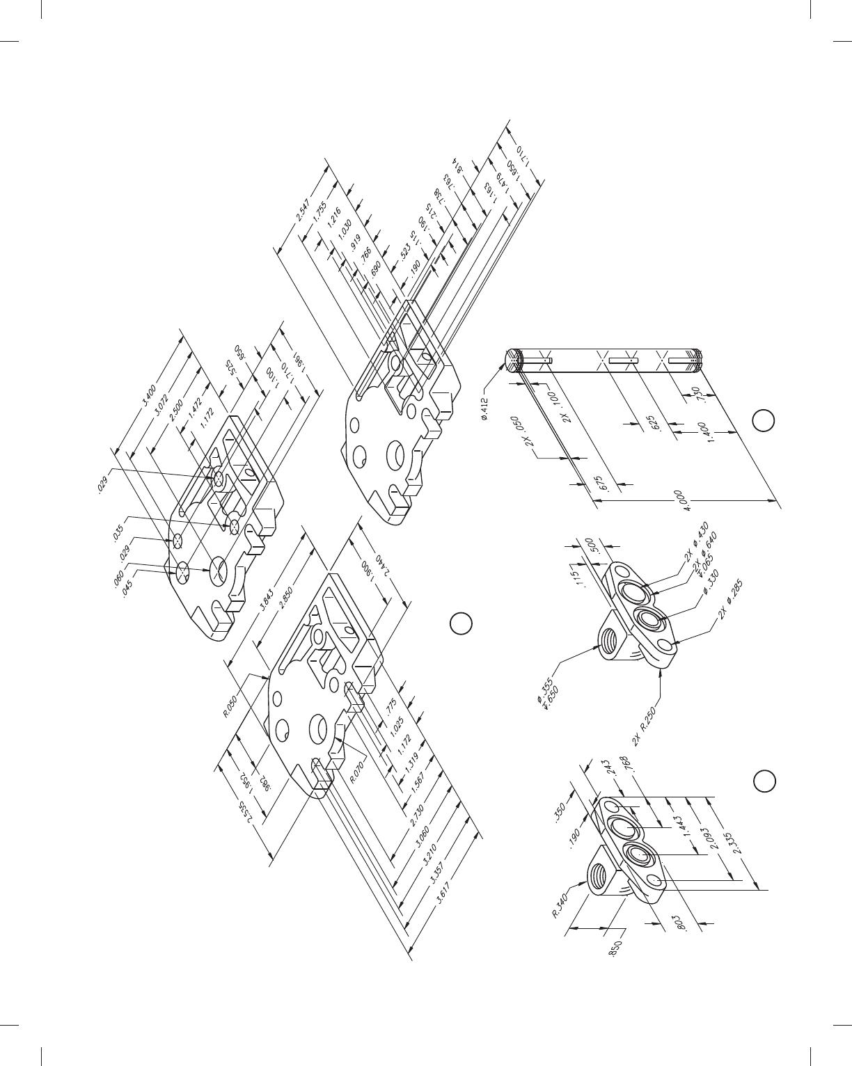
31
1 PUMP COVER
3 END COVER 4 DRIVE SHAFT
PROBLEM 15.18
(Continued)
59728_ch15_EOC_ptg01.indd 31 2/3/16 2:24 PM
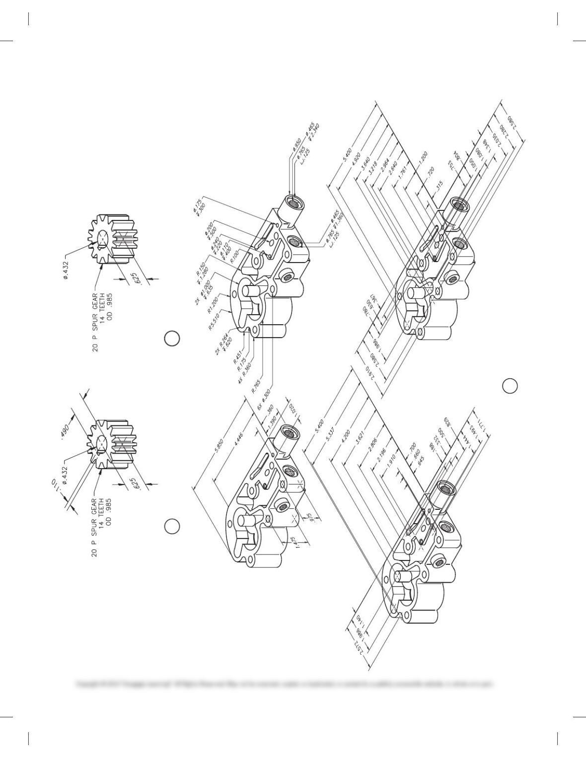
32
6 DRIVE GEAR (RETURN) 7 IDLER GEAR (RETURN)
OIL PUMP BODY8
PROBLEM 15.18
(Continued)
59728_ch15_EOC_ptg01.indd 32 2/3/16 2:24 PM
33
9 PLUNGER VALVE
10 PLUNGER SPRING
11 END CAP
12 PSI CONTROL SPRING
15 IDLER GEAR (FEED)
16 DRIVE GEAR (FEED)
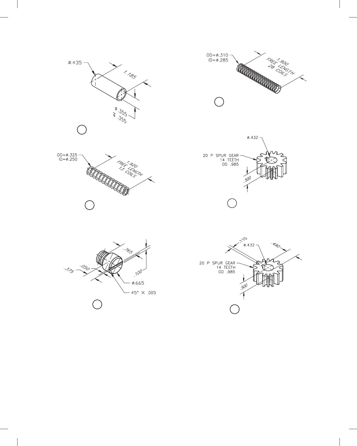
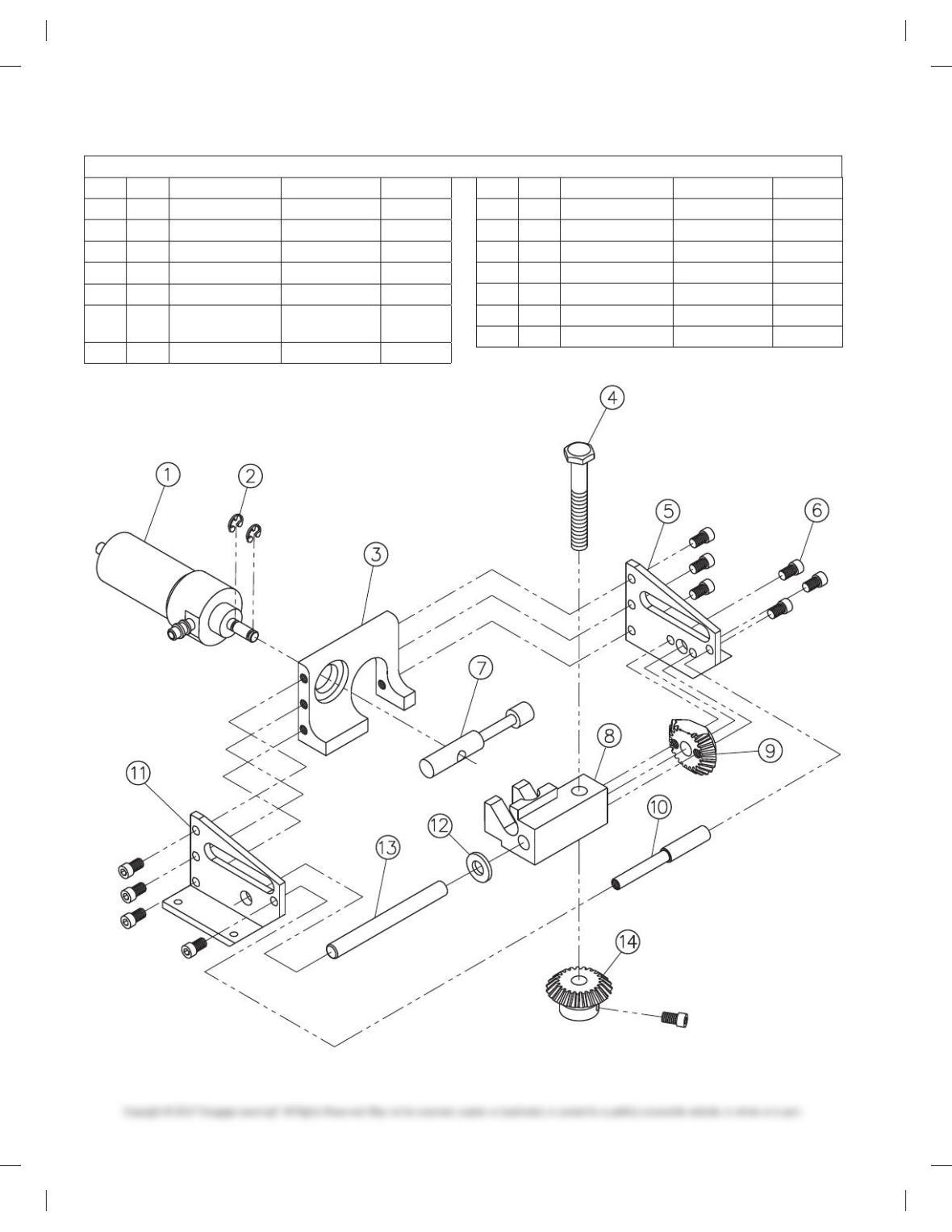
PROBLEM 15.19 Working drawing (in.)
Assembly Name: Landing Gear Retract Assembly
SPECIFIC INSTRUCTIONS: This problem is challenging and con-
tains applications that include gears. You should study gears and
related drafting practices covered in Chapter 16 Mechanisms: Link-
ages, Cams, Gears, and Bearings before completing this problem.
Prepare a complete set of working drawings with one de-
tail drawing per sheet and the assembly and parts list on
another sheet. When preparing the assembly drawing, use
separate balloons for each part in each view or use only one
balloon in the view that most clearly identifies the part. This
is an engineering prototype project. Errors are likely in this
problem. Verify dimensions during assembly. Establish toler–
ances between mating parts. There are several purchase parts
in this assembly. Manufacturer research is needed to locate
available products.
PROBLEM 15.18
(Continued)
59728_ch15_EOC_ptg01.indd 33 2/3/16 2:24 PM
34
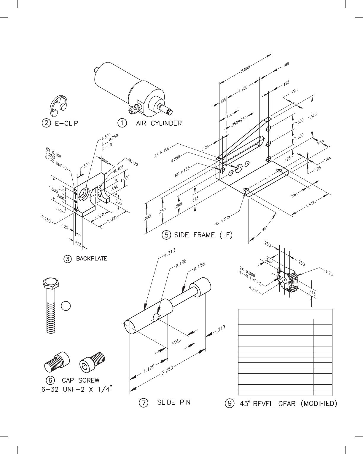
ITEM QTY NAME DESCRIPTION PART NO.
1 1 AIR CYLINDER CLIPPERD CL0002
2 2 E-CLIP 1/80 EC0018
3 1 BACKPLATE ALUMINUM LGR001
41
1/40 3 20 BOLT 20 HARD BOLT BT0002
5 1 SIDE FRAME (LF) ALUMINUM LGR003
6 11 CAP SCREW 6-32UNF-2 3
1/40
CS0012
7 1 SLIDE PIN STEEL LGR006
ITEM QTY NAME DESCRIPTION PART NO.
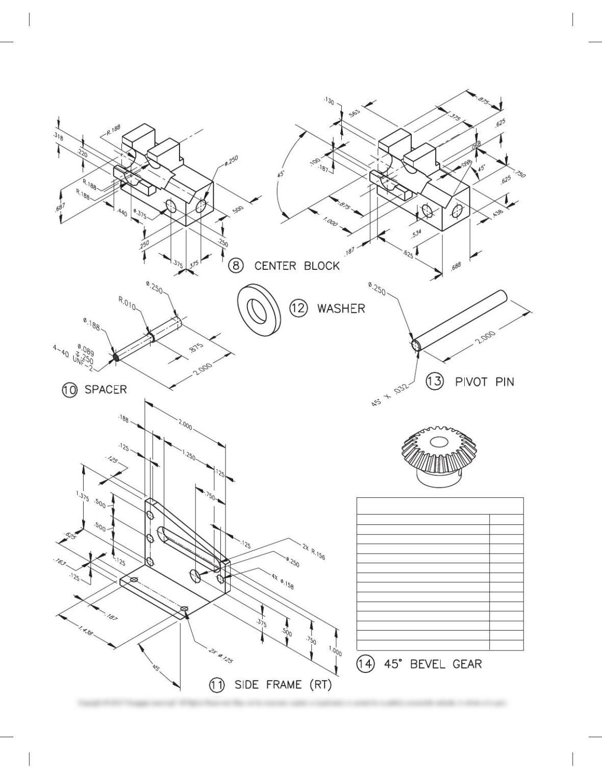
8 1 CENTER BLOCK ALUMINUM LGR005
9 1 45° BEVEL GEAR MODIFIED BG0002
10 1 SPACER ALUMINUM LGR007
11 1 SIDE FRAME (RT) ALUMINUM LGR002
12 1 WASHER BRASS WA0014
13 1 PIVOT PIN HARD STEEL LGR008
14 1 45° BEVEL GEAR BROWNING BG0001
PARTS LIST
PROBLEM 15.19
(Continued)
59728_ch15_EOC_ptg01.indd 34 2/3/16 2:24 PM
35
4 1/4″ X 2″ BOLT
20
20
20d
.707
1.000
.07854
45d
40d
.05
2.188
.052
.078
.0625
1.071
NUMBER OF TEETH
DIAMETRAL PITCH
PRESSURE ANGLE
CONE DISTANCE
PITCH DIAMETER
CIRCULAR THICKNESS (REF)
PITCH ANGLE
ROOT ANGLE
ADDENDEM
WHOLE DEPTH
CHORDAL ADDENDEM
CHORDAL THICKNESS
DEDENDUM
OUTSIDE DIAMETER
BEVEL GEAR DATA
PROBLEM 15.19
(Continued)
59728_ch15_EOC_ptg01.indd 35 2/3/16 2:24 PM
36
1/4″ BRASS
NUMBER OF TEETH
DIAMETRAL PITCH
PRESSURE ANGLE
CONE DISTANCE
PITCH DIAMETER
CIRCULAR THICKNESS (REF)
PITCH ANGLE
ROOT ANGLE
ADDENDEM
WHOLE DEPTH
CHORDAL ADDENDEM
CHORDAL THICKNESS
DEDENDUM
OUTSIDE DIAMETER
20
20
20d
.707
1.000
.07854
45d
40d
.05
2.188
.052
.078
.0625
1.071
BEVEL GEAR DATA
PROBLEM 15.19
(Continued)
59728_ch15_EOC_ptg01.indd 36 2/3/16 2:24 PM
37
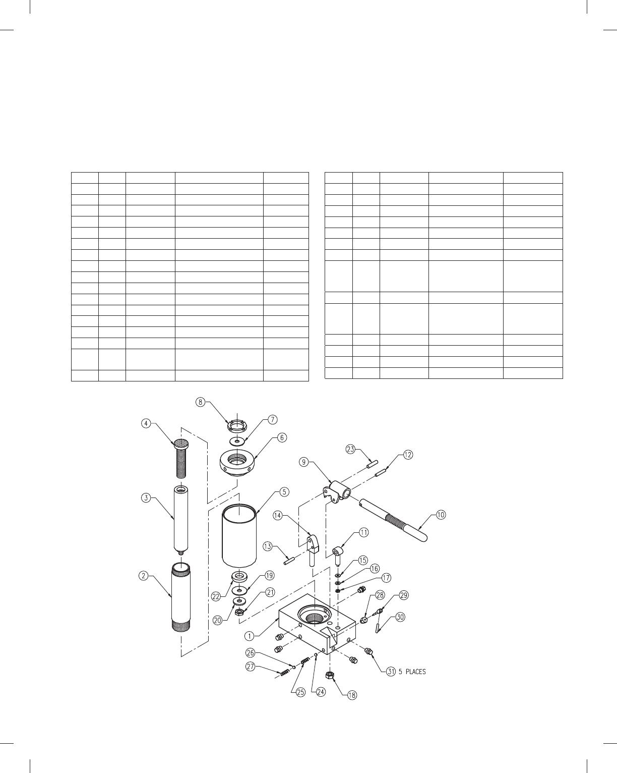
PROBLEM 15.20 Working drawing (in.)
Assembly Name: Hydraulic Jack
SPECIFIC INSTRUCTIONS: This problem is challenging and
advanced.
Prepare a complete set of working drawings with one detail
drawing per sheet and the assembly and parts list on another sheet.
When preparing the assembly drawing, use separate balloons for
each part in each view or use only one balloon in the view that most
clearly identifies the part. This is an engineering prototype project.
Errors are likely in this problem. Verify dimensions during assembly.
Establish tolerances between mating parts. Several purchase parts
and parts need to be designed in this assembly. Manufacturer re-
search is needed to locate available products.
KEY QTY NAME DESCRIPTION PART NO.
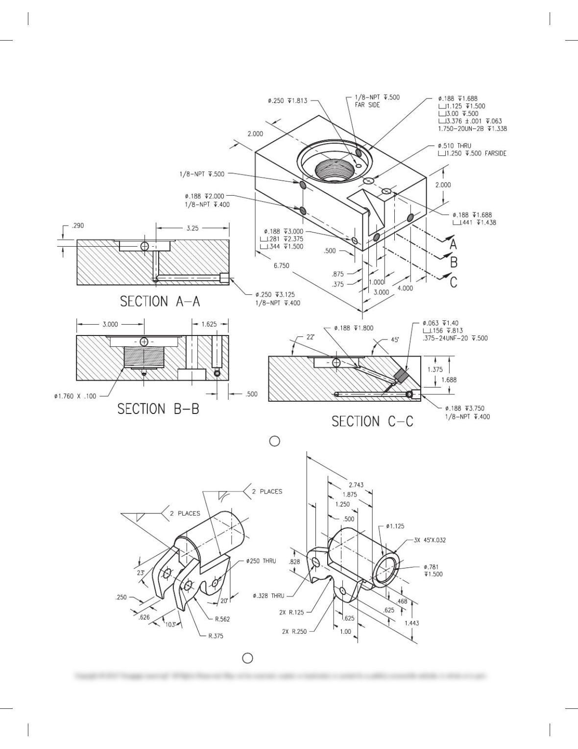
1 1 BASE JACK 1DT1001
2* 1 TUBE CYLINDER 1DT1002
3* 1 PISTON JACK 1DT1003
4* 1 SCREW JACK 1DT1004
5* 1 TUBE RESERVOIR 1DT1005
6* 1 CAP TOP 1DT1006
7 1 PACKING [ 1.500 LEATHER 5DT1007
8* 1 NUT PACKING 1DT1008
9 1 SOCKET PUMP HANDLE 1DT1009
10* 1 HANDLE PUMP 1DT1010
11* 1 PLUNGER PUMP 1DT1011
12* 1 PIN DRIVE 1DT1012
13* 1 PIN STOP 1DT1013
14* 1 SUPPORT PUMP PIVOT 1DT1014
15 1 CUP SEAL [ 445 NEOPRENE 5DT1015
16 1 WASHER ANS TYPE B PLAIN
NO. 10 N SERIES
5DT1016
17 1 NUT 10-32 UNF-2B 5DT1017
KEY QTY NAME DESCRIPTION PART NO.
18 1 NUT .437-14 UNC-2B 5DT1018
19 1 CUP [ 1.500 LEATHER 5DT1019
20* 1 WASHER PISTON 1DT1020
21 1 NUT .437-20 UNF-2B 5DT1021
22* 1 GUIDE BRONZE 1DT1022
23* 1 PIN PIVOT 1DT1023
24 1 BALL [. 250 5DT1024
25 1 SPRING [. 281 3 1.000
CLOSED ENDS,
6 COILS
5DT1025
26 1 BALL [. 3125 5DT1026
27 1 SPRING [. 343 3 1.250
CLOSED ENDS,
9 COILS
5DT1027
28* 1 NUT NEEDLE VALVE 1DT1028
29* 1 VALVE NEEDLE 1DT1029
30* 1 HANDLE NEEDLE VALVE 1DT1030
31 5 PLUG 1/8-27 NPT 5DT1031
*Engineering layouts are not provided for these parts. These parts
need to be designed to complete this set of working drawings.
Possible drawing solutions are provided in the Solutions Manual
for Engineering Drawing and Design, Sixth Edition.
*
*
*
*
*
*
*
*
*
*
*
*
*
*
**
*
59728_ch15_EOC_ptg01.indd 37 2/3/16 2:24 PM
38
1 BASE
9 SOCKET
PROBLEM 15.20
(Continued)
59728_ch15_EOC_ptg01.indd 38 2/3/16 2:24 PM
39
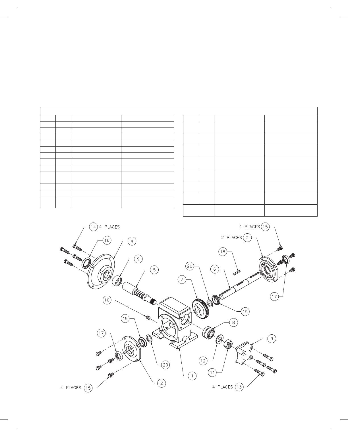
ITEM QTY NAME DESCRIPTION
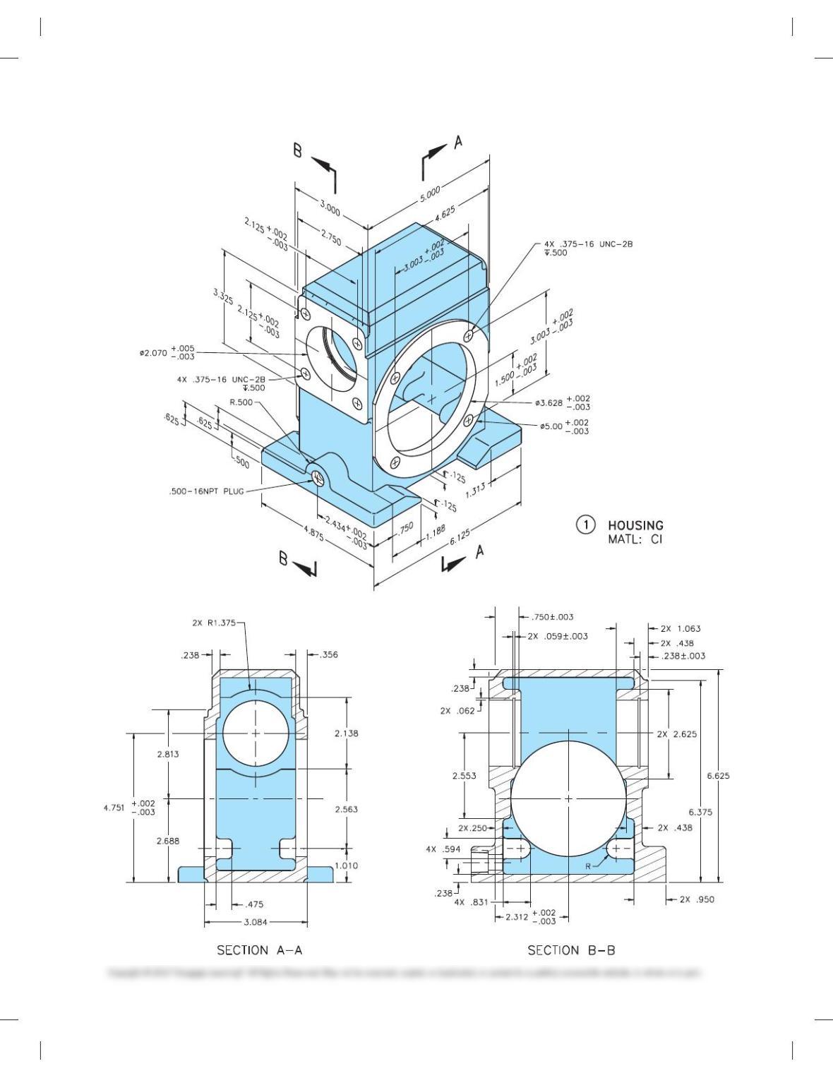
1 1 HOUSING
2 2 RETAINING PLATE
3 1 BEARING CAP
4 1 MOTOR ADAPTER
5 1 HIGH SPEED SHAFT
6 1 SLOW SPEED SHAFT
7 1 WORM GEAR BRONZE
8 1 DBL. ROW TAPERED KOYO46T30305DJ/29.5
9 1 SNGL. ROLE CYL.
ROLLER BEARING
KOYO CRL11
10 1 TAPER PLUG 500-16NPT PLUG
11 1 HEX NUT .875-16 UN-28
12 4 HIGH SPEED
LOCKWASHER
TIMKEN TW-105
ITEM QTY NAME DESCRIPTION
13 4 MACHINE SCREW .375-16UNC-2A 3
1.813 HEX HEAD
14 4 MACHINE SCREW .375-16UNC-2A 3
1.625 HEX HEAD
15 8 MACHINE SCREW .375-16UNC-2A 3 .625
HEX HEAD
16 1 HIGH SPEED OIL
SEAL
PARKER 2-028
17 2 SLOW SPEED OIL
SEAL
PARKER 2-020
18 1 SLOW SPEED
KEYWAY
.1875 3 .245 3 1.450
19 1 SNGL. ROW TAP
ROLLER BEARING
KOYO 32005J
20 2 SLOW SPEED
SPACER
TIMKEN TW-506
PROBLEM 15.21 Working drawing (in.)
Assembly Name: Worm Gear Reducer
SPECIFIC INSTRUCTIONS: This problem is demanding, and it
contains challenging applications that include gears and bearings.
You should study gears and related drafting practices covered in
Chapter 16, Mechanisms: Linkages, Cams, Gears, and Bearings,
before completing this problem. This is an advanced project, and
design changes can be required. Prepare a complete set of working
drawings with one detail drawing per sheet and the assembly and
parts list on another sheet. When preparing the assembly drawing,
use separate balloons for each part in each view or use only one
balloon in the view that most clearly identifies the part. This is an
engineering prototype project. Errors are likely in this problem.
Verify dimensions during assembly. Establish tolerances between
mating parts. A completed assembly drawing and parts list for this
problem is shown in Figure 15.24.
PARTS LIST
59728_ch15_EOC_ptg01.indd 39 2/3/16 2:24 PM
40
PROBLEM 15.21
(Continued)
59728_ch15_EOC_ptg01.indd 40 2/3/16 2:24 PM