41
PROBLEM 15.21
(Continued)
59728_ch15_EOC_ptg01.indd 41 2/3/16 2:24 PM
42
PROBLEM 15.21
(Continued)
59728_ch15_EOC_ptg01.indd 42 2/3/16 2:24 PM
43
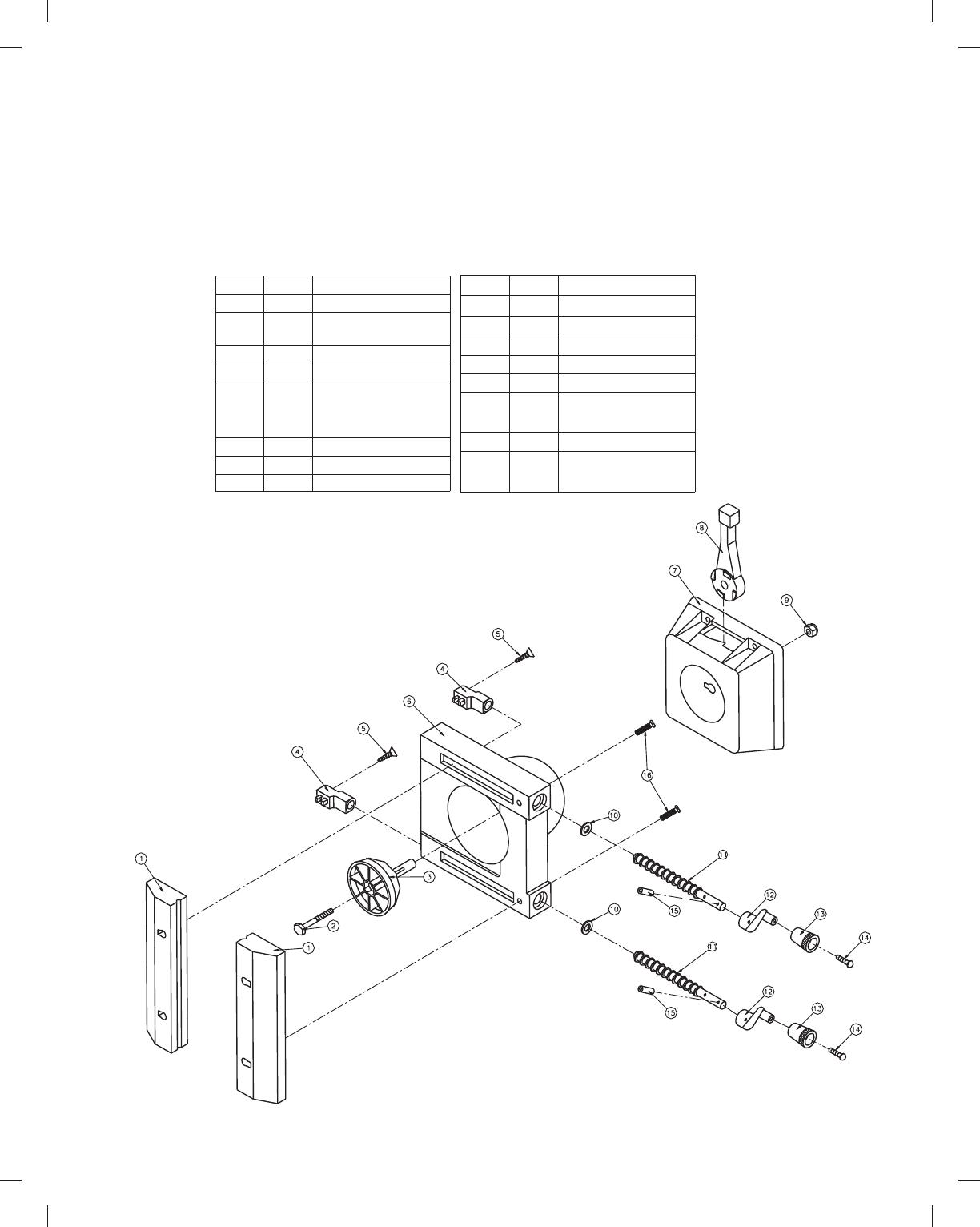
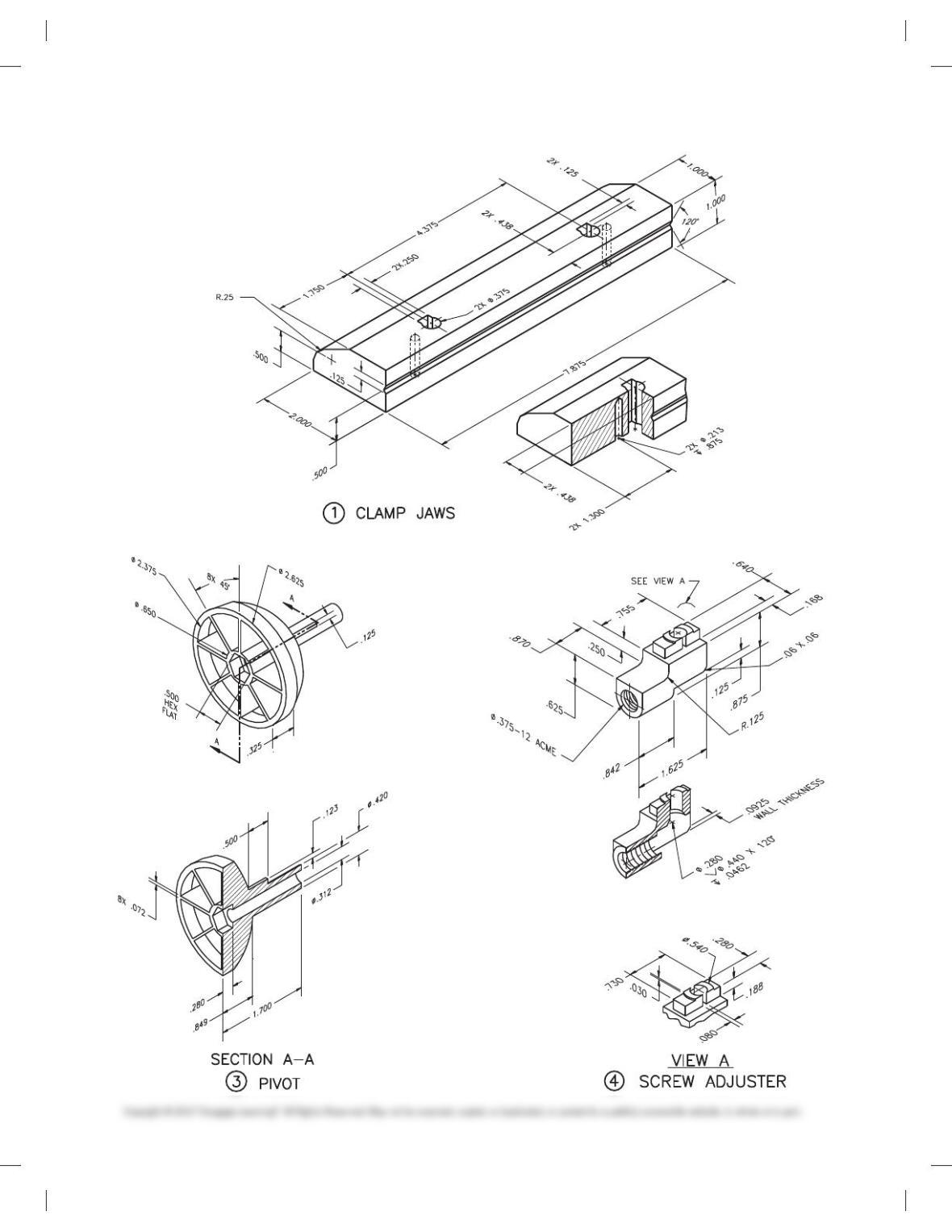
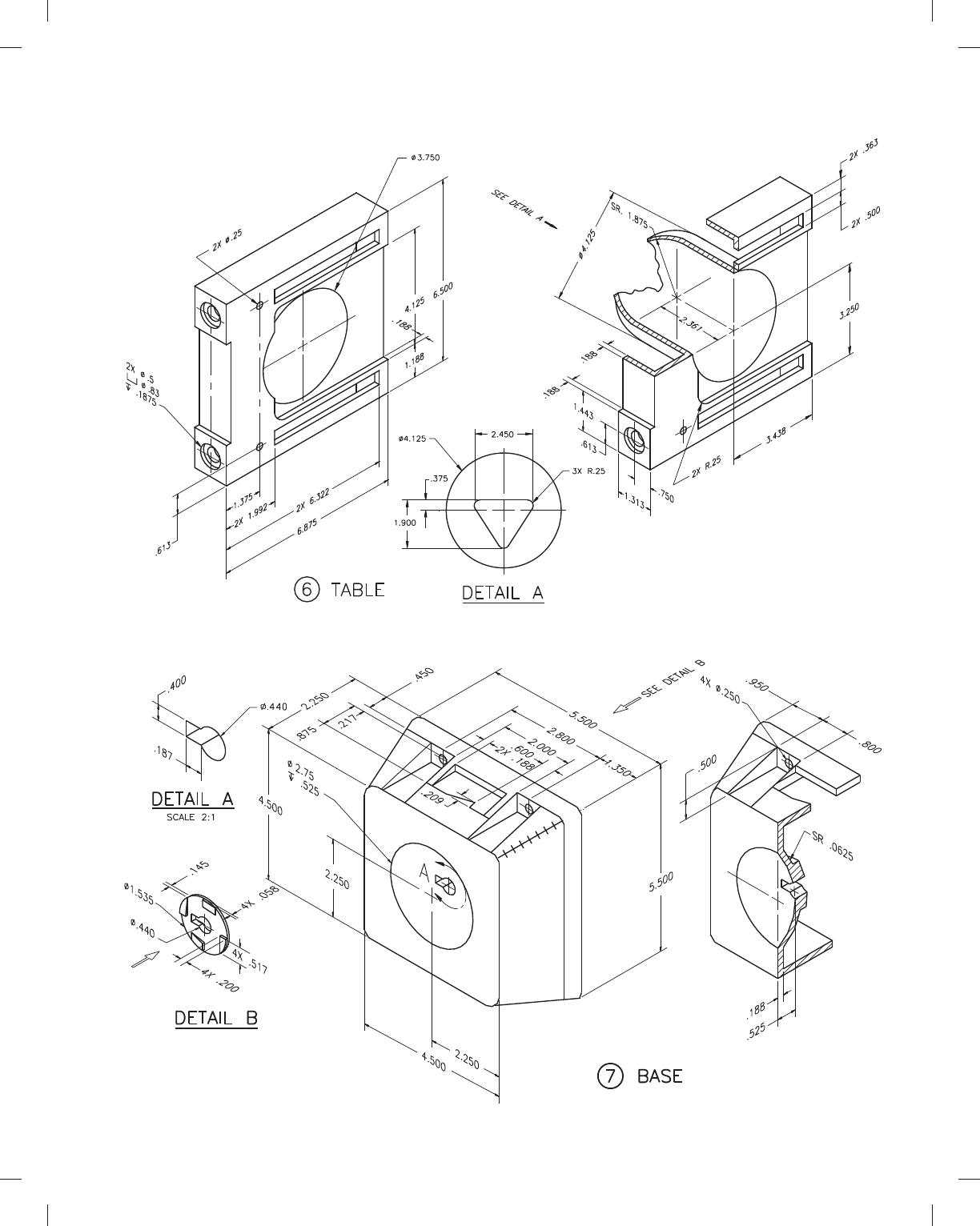
PROBLEM 15.22 Working drawing (in.)
Assembly Name: Table Vise
SPECIFIC INSTRUCTIONS: Prepare a complete set of working
drawings with one detail drawing per sheet and the assembly
and parts list on another sheet. When preparing the assembly
PARTS LIST
KEY QTY DESCRIPTION
KEY QTY DESCRIPTION
1 2 CLAMP JAWS
3 1 PIVOT
6 1 TABLE
7 1 BASE
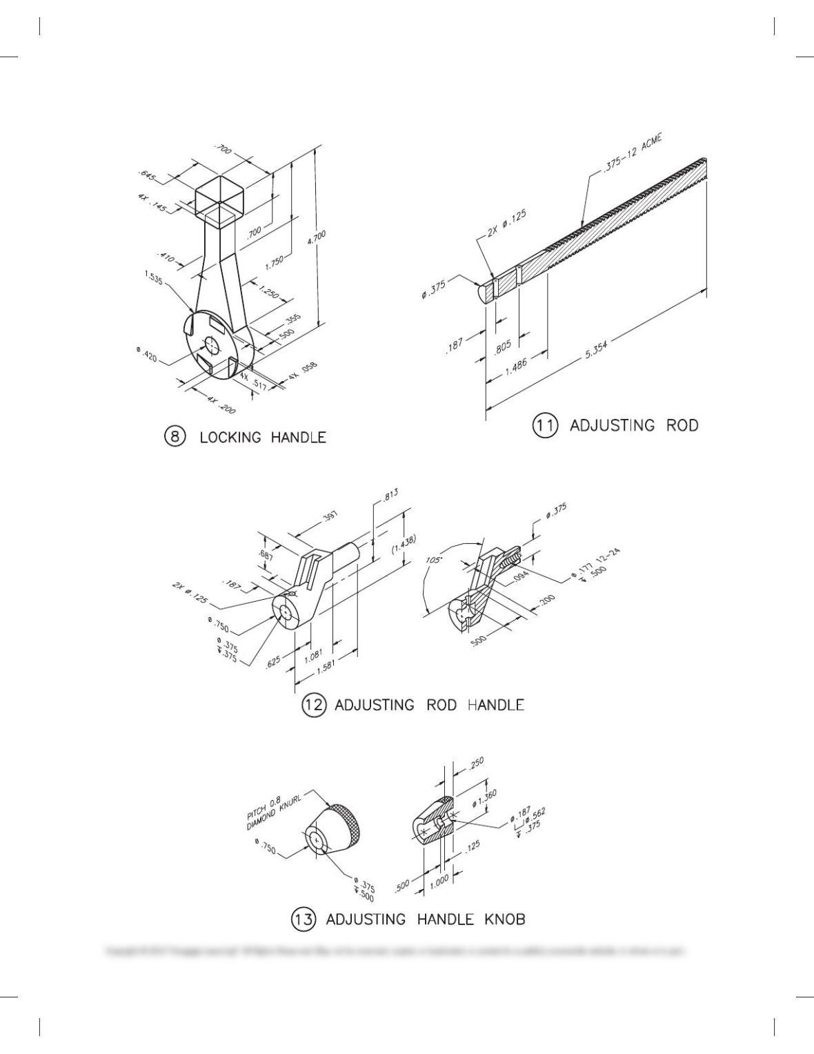
8 1 LOCKING HANDLE
9 1 1/4-28UNF NYLOCK NUT
10 2 3/8 FLAT WASHER
11 2 ADJUSTING ROD
13 2
ADJUSTING HANDLE KNOB
12 2 ADJUSTING ROD HANDLE
21
1/4 -28UNF X 2″ LG
HEX HD MACH. SCREW
4 2 SCREW ADJUSTER
52
1/4-28UNF X 1″ LG
STANDARD SLOT FLAT
COUNTERSUNK HD
CAP SCREW
14 2
8-32UNC X 5/8″ LG
SLOTTED ROUND HD.
MACHINE SCREW
15 2 1/8 SPRING PIN
1/4-28UNF X 1″ LG
STANDARD SLOT PAN
HEAD MACHINE SCREW
216
drawing, use separate balloons for each part in each view or use
only one balloon in the view that most clearly identifies the part.
This is an engineering prototype project. Errors are likely in this
problem. Verify dimensions during assembly. Establish toler-
ances between mating parts.
59728_ch15_EOC_ptg01.indd 43 2/3/16 2:24 PM
44
PROBLEM 15.22
(Continued)
59728_ch15_EOC_ptg01.indd 44 2/3/16 2:24 PM
45
PROBLEM 15.22
(Continued)
59728_ch15_EOC_ptg01.indd 45 2/3/16 2:24 PM
46
PROBLEM 15.22
(Continued)
59728_ch15_EOC_ptg01.indd 46 2/3/16 2:24 PM

47
ADVANCED TEAM DESIGN PROBLEMS
Part 2: Problems 15.23 and 15.24
These problems are suited to a team approach. It is recom-
mended that different parts of the project be assigned to each
team member. Team members must coordinate mating parts
during the development of the working drawings. This is an en-
gineering prototype project. Errors are likely. Verify dimensions
during assembly. Establish tolerances between mating parts. If
errors are encountered, the team members should meet to re-
solve conflicts and establish alternatives.
Prepare a complete set of working drawings with one detail
drawing per sheet, and the subassembly, assembly, and parts lists
on separate sheets. When preparing the subassembly and assembly
drawings, use separate balloons for each part in each view or use
only one balloon in the view that most clearly identifies the part.
TEAM PROBLEMS
The following advanced problems can be assigned as team prob-
lems as determined by the instructor and course objectives.
Team problems are provided that can be used as projects
that help foster leadership and cooperation between team mem-
bers to design and draw complete sets of working drawings for a
product. Teams are established with any desired number of
members based on the project and curriculum goals. Teams can
select an engineer by voting in a democratic process, by select-
ing the person with the highest course evaluation, or as deter–
mined by the instructor. Anengineercreates designs and is the
person in charge of the project. The engineer coordinates the
team work, monitors the progress, and provides answers and
instructions to the team members in cooperation with the in-
structor. The engineerdivides the project into tasks and assigns
portions of the project to the drafting team members. The engi-
neer works with team members to establish design alternatives.
Team members are drafters, with one drafter responsible for
sheet layout and reproduction. Each drafter is assigned specific
drawing for the completion of the entire set of drawings. The
engineer provides coordination between team members to con-
firm all parts of the project match. Final team assignments and
members are determined by your instructor. A checker is se-
lected using criteria similar to choosing the engineer. The
checker works with drafting team members to advice on the
proper use of standards. The checker evaluates each completed
drawing to make sure drafting standards are properly applied.
The checker can redline a print with requested corrections that
are returned to drafting for final completion. The checker coor–
dinates and consults with the engineer and instructor to make
sure drawings are completed in accordance with design require-
ments and industry standards.
Team evaluation criteria:
Team project evaluation includes:
Project coordination: organization of project assignments.
Project completion: complete set of working drawings
finished.
Team member cooperation.
Project quality: drawings completed accurately and in a pro-
fessional manner.
Engineering decisions:
Project properly interpreted.
Design decisions properly evaluated and completed.
59728_ch15_EOC_ptg01.indd 47 2/3/16 2:24 PM
48
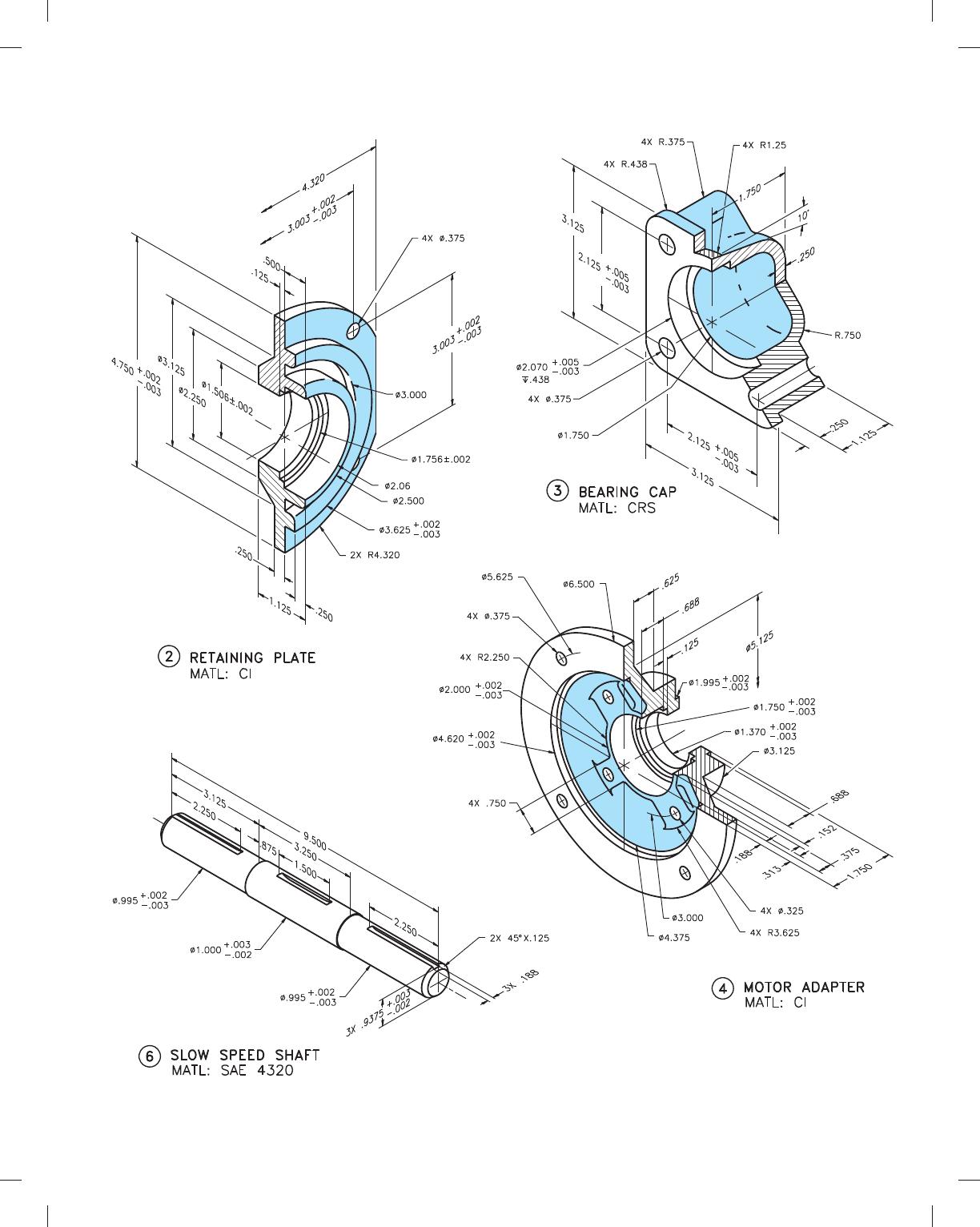
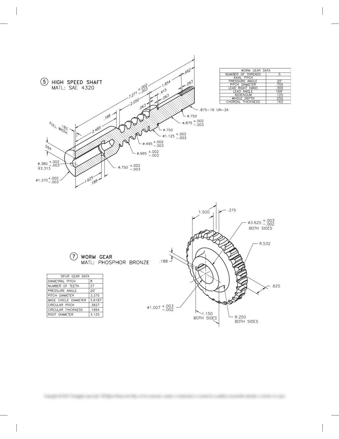
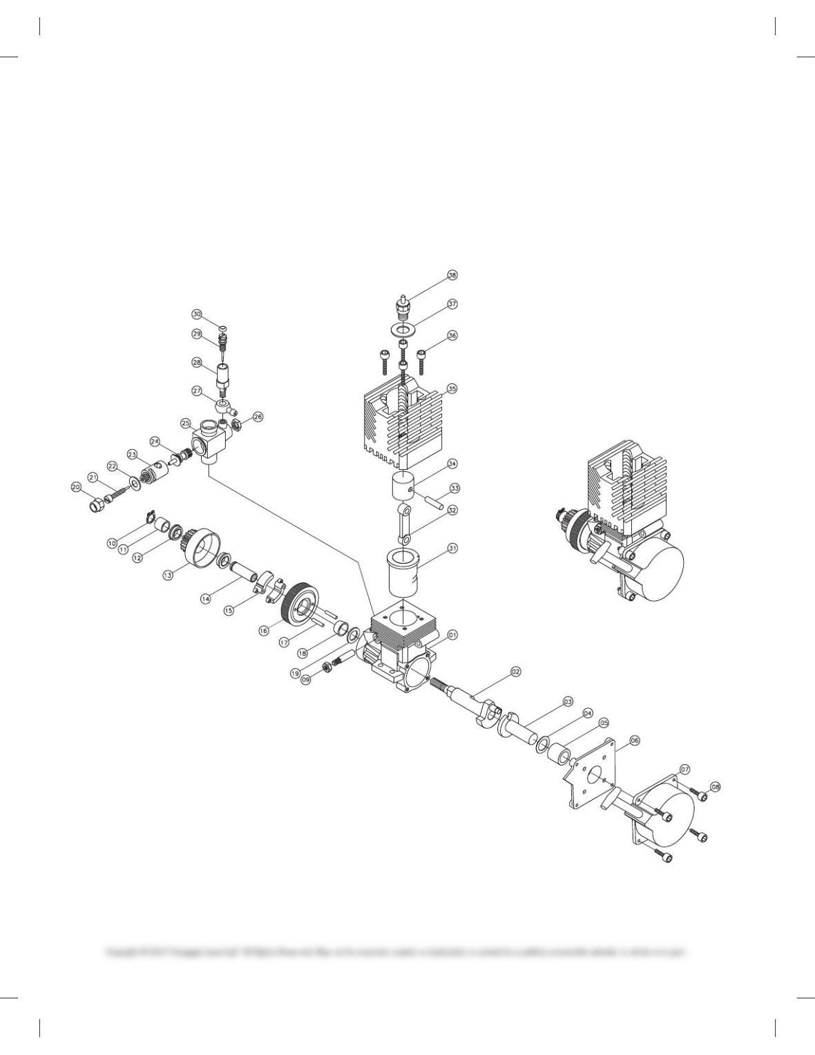
PROBLEM 15.23 Working drawing (in.)
Assembly Name: Motor
Courtesy Timothy Y. Taylor and Matthew Bell.
SPECIFIC INSTRUCTIONS: This problem is advanced, and con-
tains challenging applications that include gears, bearings, and
seals. You should study gears and related drafting practices cov-
ered in Chapter 16 before completing this problem.
59728_ch15_EOC_ptg01.indd 48 2/3/16 2:24 PM

49
PROBLEM 15.23
(Continued)
REQD
1
1
1
1
1
1
1
4
1
QTY
NOMENCLATURE
OR DESCRIPTION OF MAIN ASSEMBLYIDENTIFYING NO.
PART ORITEM
NO.
O.S. MAX GAS MOTOR
BEVELED SLEEVE
WASHER
CLUTCH PIN
CLUTCH HOUSING
BRAKE PAD
CLUTCH SLEEVE
CLUTCH GEAR
CLUTCH BEARING
CLUTCH SLEEVE
HORSESHOE CLIP
REFER TO FOLLOWING PAGES
REFER TO FOLLOWING PAGES
REFER TO FOLLOWING PAGES
REFER TO FOLLOWING PAGES
REFER TO FOLLOWING PAGES
I.D. Ø.025 ⫻ .O.D. Ø.042 ⫻ .015THK
Ø.075 ⫻ .375
REFER TO FOLLOWING PAGES
REFER TO FOLLOWING PAGES
ESTABLISH PURCHASE PART
RUBBER SEAL
FUEL INTAKE ADJUSTER PIN
FUEL ADJUSTER
FUEL INTAKE
HEX NUT
CARBURETOR HOUSING
GAS REGULATOR
MIXTURE CONTROL
AIR ADJUSTER
HEX CAP
REFER TO FOLLOWING PAGES
1/4-16UNC-2
REFER TO FOLLOWING PAGES
REFER TO FOLLOWING PAGES
ESTABLISH PURCHASE PART
REFER TO FOLLOWING PAGES
REFER TO FOLLOWING PAGES
REFER TO FOLLOWING PAGES
REFER TO FOLLOWING PAGES
REFER TO FOLLOWING PAGES
REFER TO FOLLOWING PAGES
PISTON SHAFT
GLOW PLUG
WASHER
HEX SCREW
HEAT SINK
PISTON
PISTON PIN
CRANK ARM
REFER TO FOLLOWING PAGES
REFER TO FOLLOWING PAGES
REFER TO FOLLOWING PAGES
REFER TO FOLLOWING PAGES
ESTABLISH PURCHASE PART
ESTABLISH PURCHASE PART
REFER TO FOLLOWING PAGESMAIN HOUSING
01
02
03
04
05
06
07
08
09
10
11
12
13
14
15
16
17
18
19
20
21
22
23
24
25
26
27
28
29
30
31
32
33
34
35
36
37
38
SCREW LOCK
CAP SCREW
STARTER HOUSING
FACE PLATE
SLEEVE
WASHER
PULLEY SHAFT
CRANKSHAFT
REFER TO FOLLOWING PAGES
REFER TO FOLLOWING PAGES
3-48UNC-2 ⫻ .250″
I.D.Ø.316 O.D.Ø.475 ⫻ .015THK
REFER TO FOLLOWING PAGES
REFER TO FOLLOWING PAGES
DESIGN OR FIND ALTERNATE PURCHASE
1
1
2
1
1
2
1
2
1
1
1
1
1
1
1
1
1
1
1
1
1
1
1
1
1
1
1
1
1
REFER TO FOLLOWING PAGES
REFER TO FOLLOWING PAGES
3-48UNC-2 ⫻ .375″
WASHER
59728_ch15_EOC_ptg01.indd 49 2/3/16 2:24 PM
50
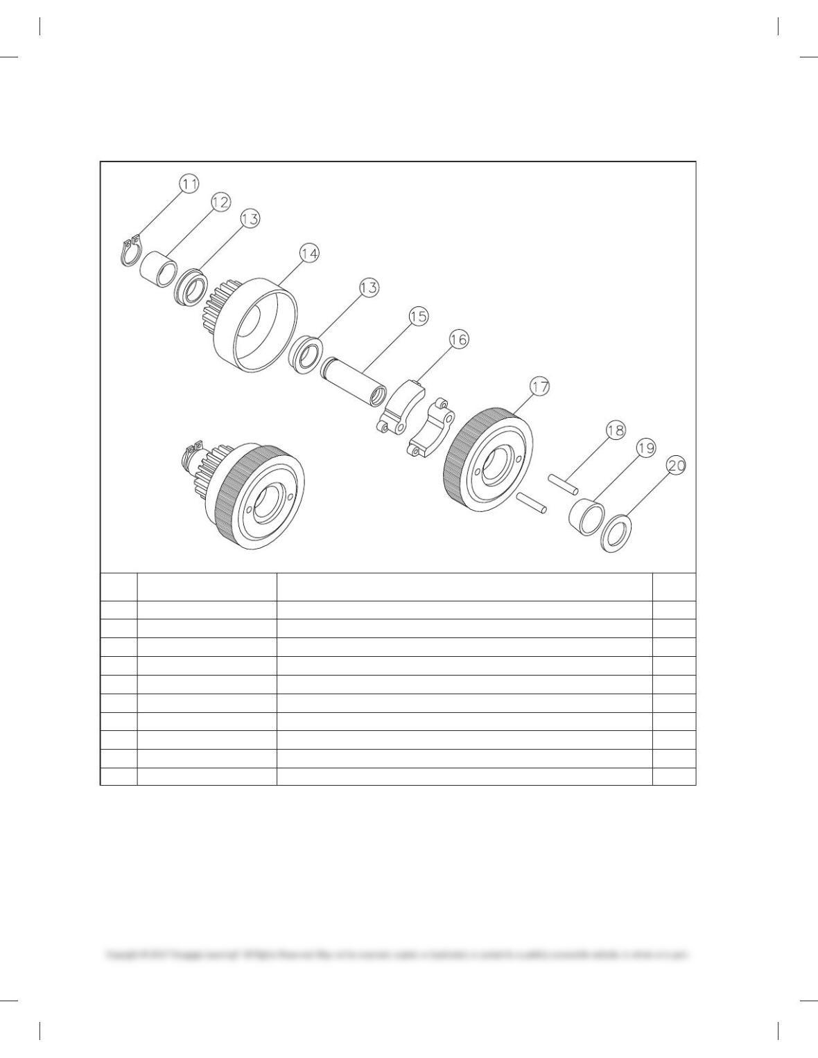
PROBLEM 15.23
(Continued)
OR DESCRIPTION OF CLUTCH ASSEMBLY
IDENTIFYING NO.
PART OR
CLUTCH ASSEMBLY
NOMENCLATUREITEM
NO.
QTY
REQD
11
12
14
15
16
17
18
13
HORSESHOE CLIP
CLUTCH SLEEVE
CLUTCH BEARING
CLUTCH GEAR
CLUTCH SLEEVE
BRAKE PAD
CLUTCH HOUSING
CLUTCH PIN
1
1
2
1
1
2
1
2
REFER TO FOLLOWING PAGES
ESTABLISH PURCHASE PART
REFER TO FOLLOWING PAGES
REFER TO FOLLOWING PAGES
REFER TO FOLLOWING PAGES
REFER TO FOLLOWING PAGES
Ø.075 ⫻ .375
REFER TO FOLLOWING PAGES
BEVELED SLEEVE
WASHER
19
20
REFER TO FOLLOWING PAGES
I.D. Ø.025 ⫻ O.D. Ø.042 ⫻ .015THK
1
1
59728_ch15_EOC_ptg01.indd 50 2/3/16 2:24 PM
51
PROBLEM 15.23
(Continued)
REQD
QTY
1
1
1
1
1
1
1
1
1
1
1
PART OR
IDENTIFYING NO.
ITEM
NO.
NOMENCLATURE
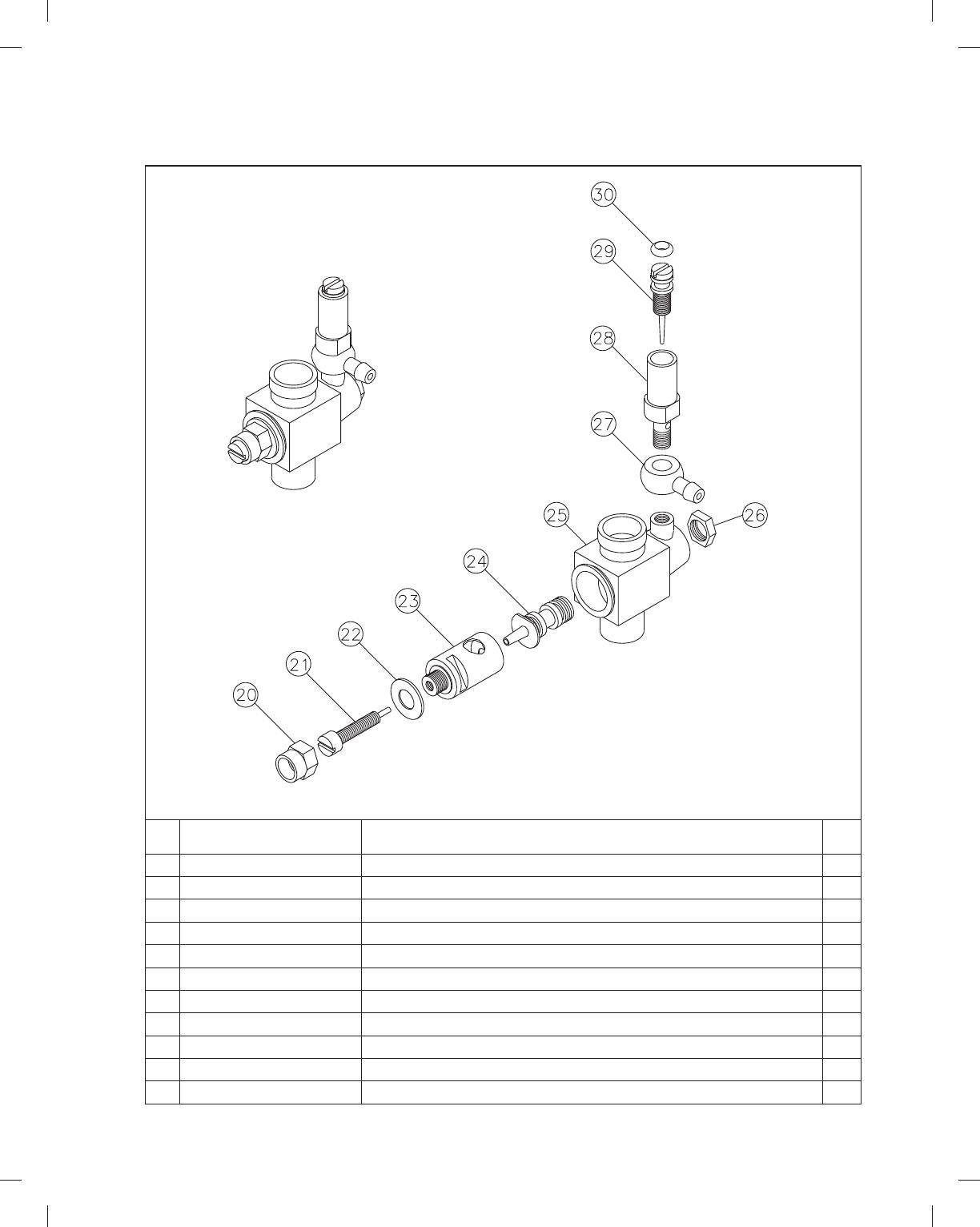
OR DESCRIPTION OF CARBURETOR SUBASSEMBLY
RUBBER SEAL
FUEL INTAKE ADJUSTER PIN
FUEL ADJUSTER
FUEL INTAKE
HEX NUT
CARBURETOR HOUSING
GAS REGULATOR
MIXTURE CONTROL
WASHER
AIR ADJUSTER
HEX CAP
30
29
28
27
26
25
24
20
22
23
21
REFER TO FOLLOWING PAGES
REFER TO FOLLOWING PAGES
REFER TO FOLLOWING PAGES
ESTABLISH PURCHASE PART
REFER TO FOLLOWING PAGES
REFER TO FOLLOWING PAGES
1/4-16UNC-2
REFER TO FOLLOWING PAGES
REFER TO FOLLOWING PAGES
REFER TO FOLLOWING PAGES
REFER TO FOLLOWING PAGES
CARBURETOR SUBASSEMBLY
59728_ch15_EOC_ptg01.indd 51 2/3/16 2:24 PM
52
PROBLEM 15.23
(Continued)
59728_ch15_EOC_ptg01.indd 52 2/3/16 2:24 PM
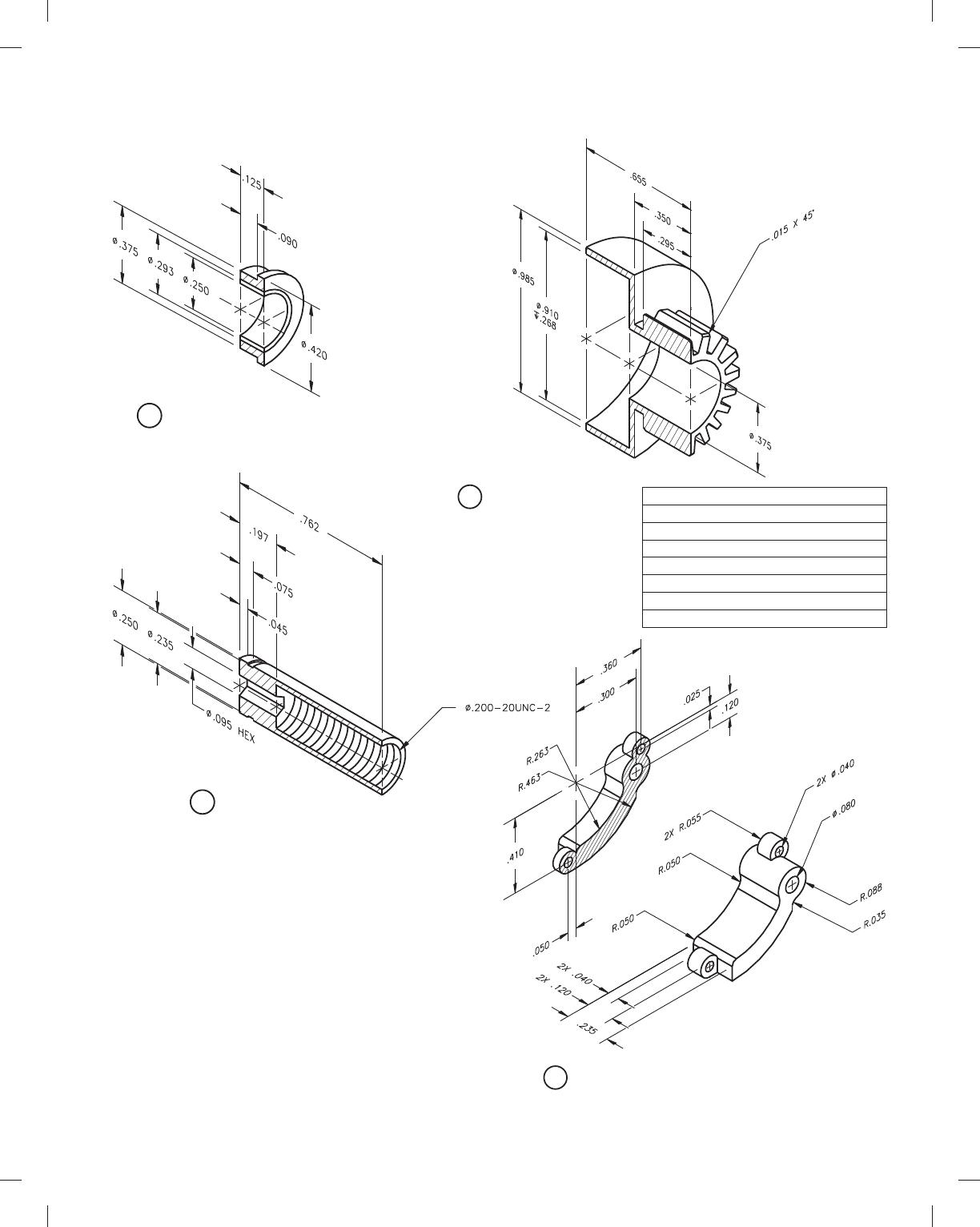
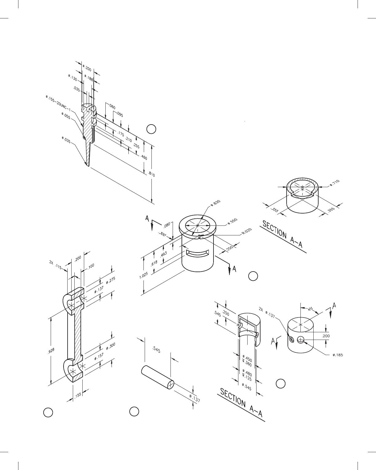
53
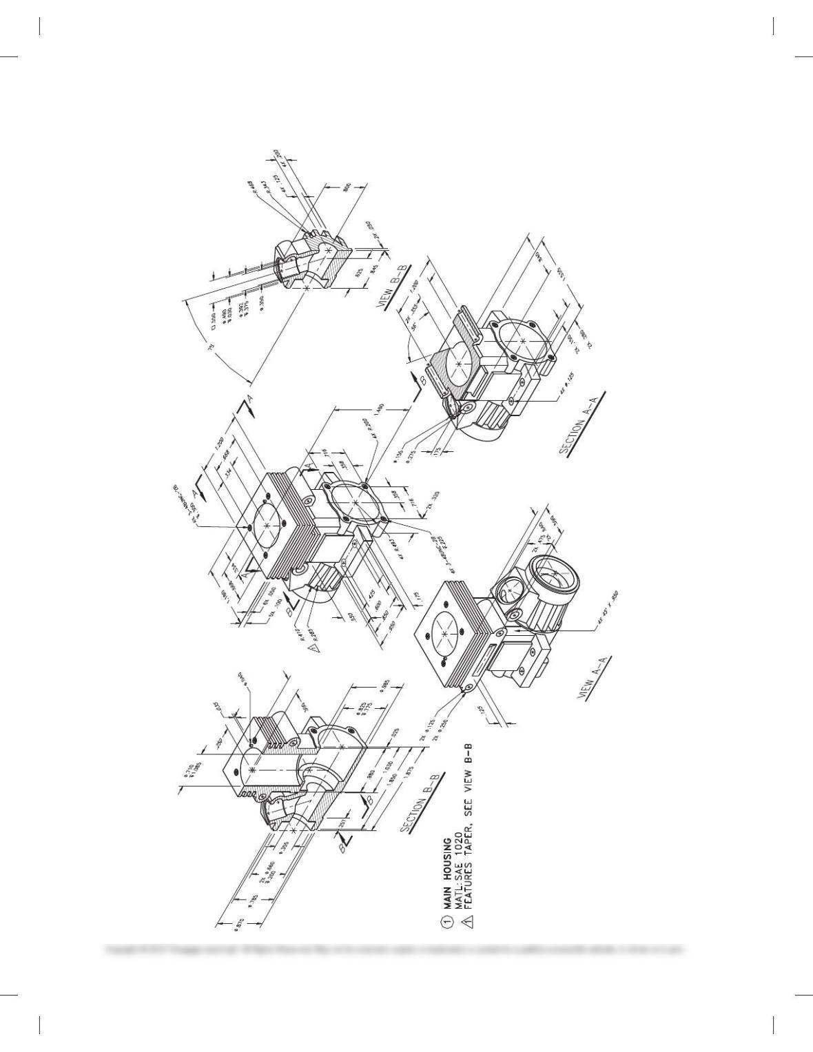
PROBLEM 15.23
(Continued)
2CRANKSHAFT
MATL: SAE 1020
3PULLEY SHAFT
MATL: SAE 1020
5SLEEVE
MATL: PHOSPHOR–BRONZE
59728_ch15_EOC_ptg01.indd 53 2/3/16 2:24 PM
54
PROBLEM 15.23
(Continued)
6FACE PLATE
MATL: SAE 1020
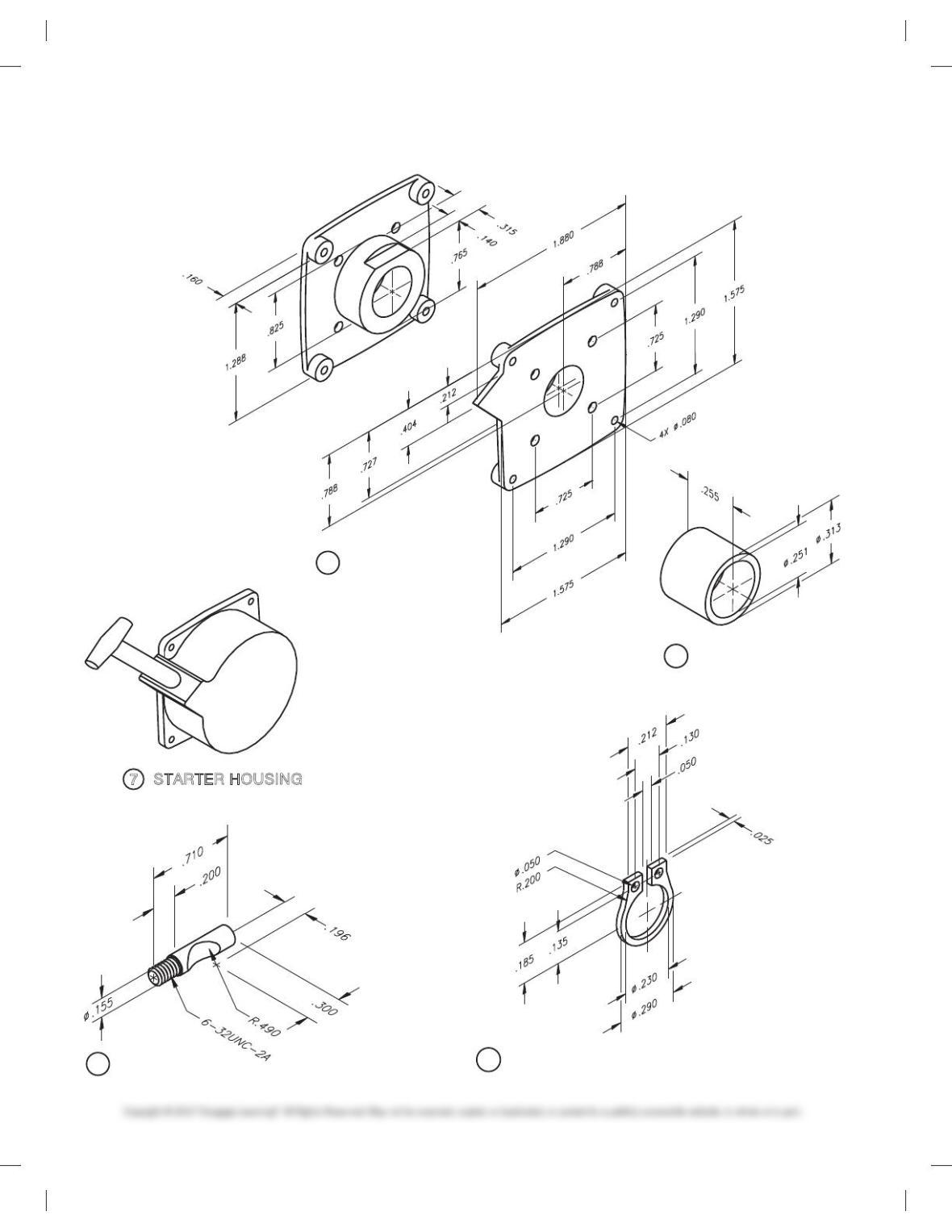
7STARTER HOUSING
9SCREW LOCK
MATL: SAE 2330
10
HORSESHOE CLIP
MATL: ACETAL THERMOPLASTIC
11
CLUTCH SLEEVE
MATL: SAE 1020
59728_ch15_EOC_ptg01.indd 54 2/3/16 2:24 PM
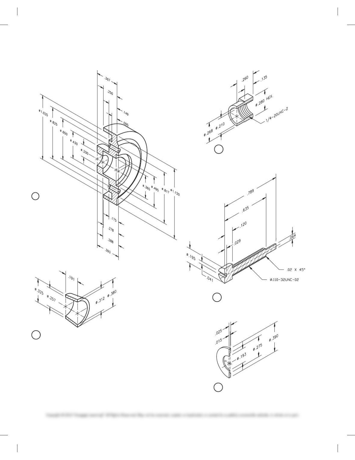
55
PROBLEM 15.23
(Continued)
SPUR GEAR DATA
BASE CIRCLE DIAMETER
CIRCULAR PITCH
ROOT DIAMETER
CIRCULAR THICKNESS
NUMBER OF TEETH
PRESSURE ANGLE
DIAMETRAL PITCH
.583
.5344
.108
.054
18
20º
29
13
CLUTCH GEAR
MATL: SAE 1020
14
CLUTCH SLEEVE
MATL: SAE 1060
15
BRAKE PAD
MATL: ACETAL THERMOPLASTIC
12
CLUTCH BEARING
MATL: BRONZE
59728_ch15_EOC_ptg01.indd 55 2/3/16 2:24 PM
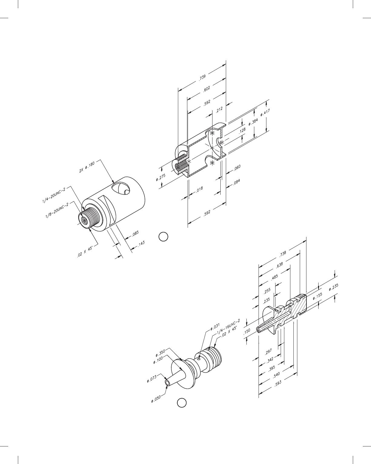
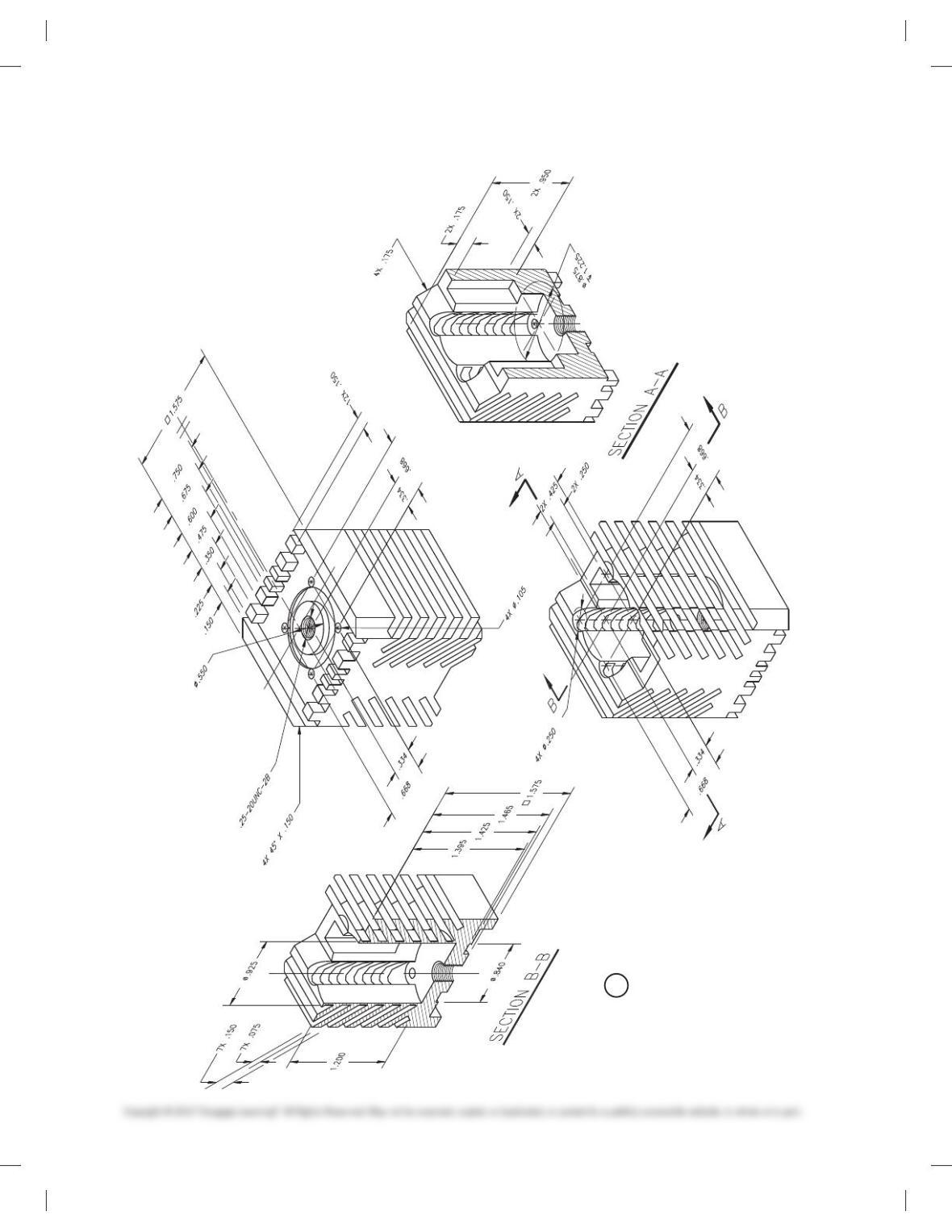
56
PROBLEM 15.23
(Continued)
16
CLUTCH HOUSING
MATL.– SAE 1020
18
BEVELED SLEEVE
MATL: PHOSPHOR–BRONZE
20 HEX CAP
MATL: SAE 1020
22 WASHER
MATL: PLASTIC
21 AIR ADJUSTER
MATL: SAE 1020
59728_ch15_EOC_ptg01.indd 56 2/3/16 2:24 PM
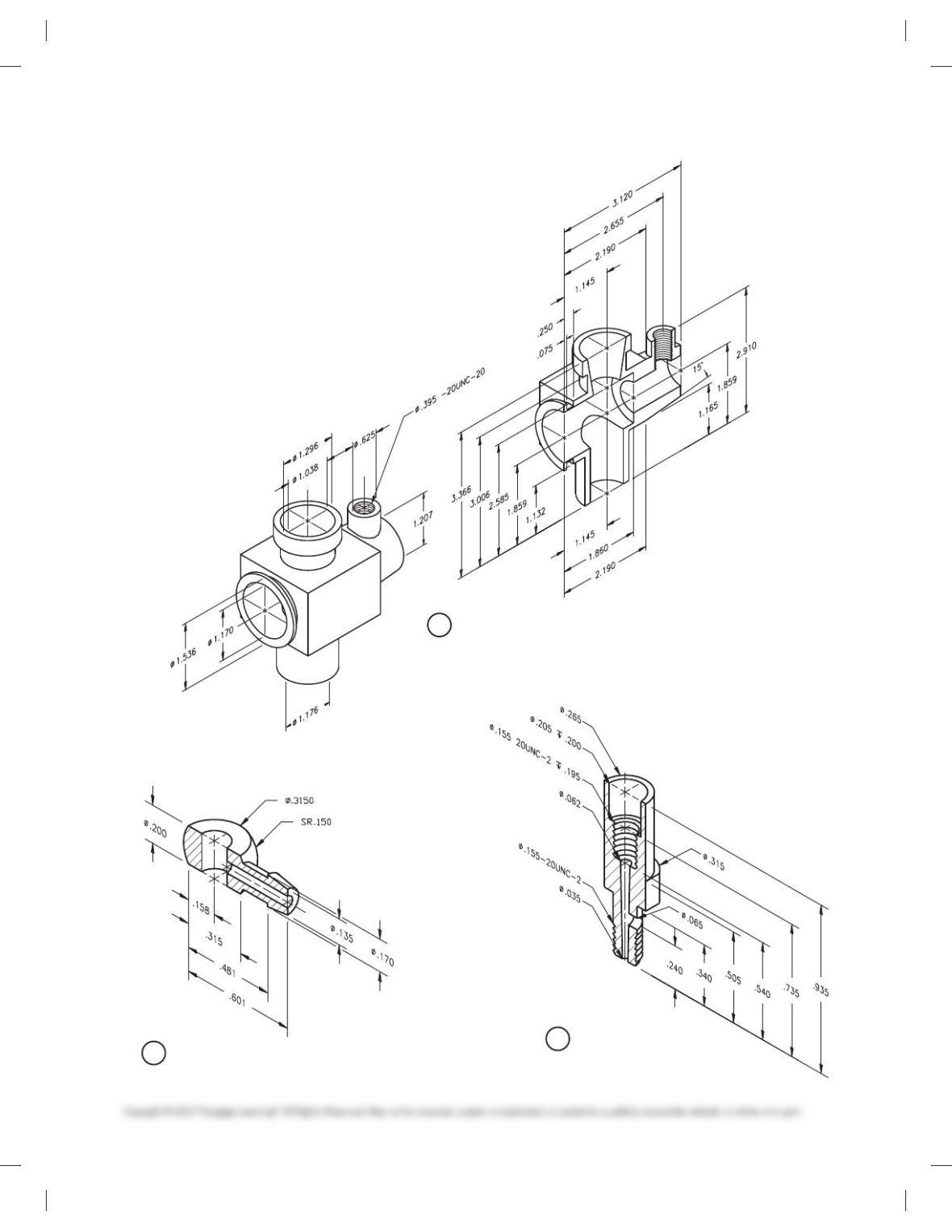
57
PROBLEM 15.23
(Continued)
23 MIXTURE CONTROL
MATL: SAE 1020
24 GAS REGULATOR
MATL: SAE 1020
59728_ch15_EOC_ptg01.indd 57 2/3/16 2:24 PM
58
PROBLEM 15.23
(Continued)
25 CARBURETOR HOUSING
MATL: SAE 1020
27 FUEL INTAKE
MATL: ACETAL THERMOPLASTIC
28 FUEL ADJUSTER
MATL: BRONZE
59728_ch15_EOC_ptg01.indd 58 2/3/16 2:24 PM
59
PROBLEM 15.23
(Continued)
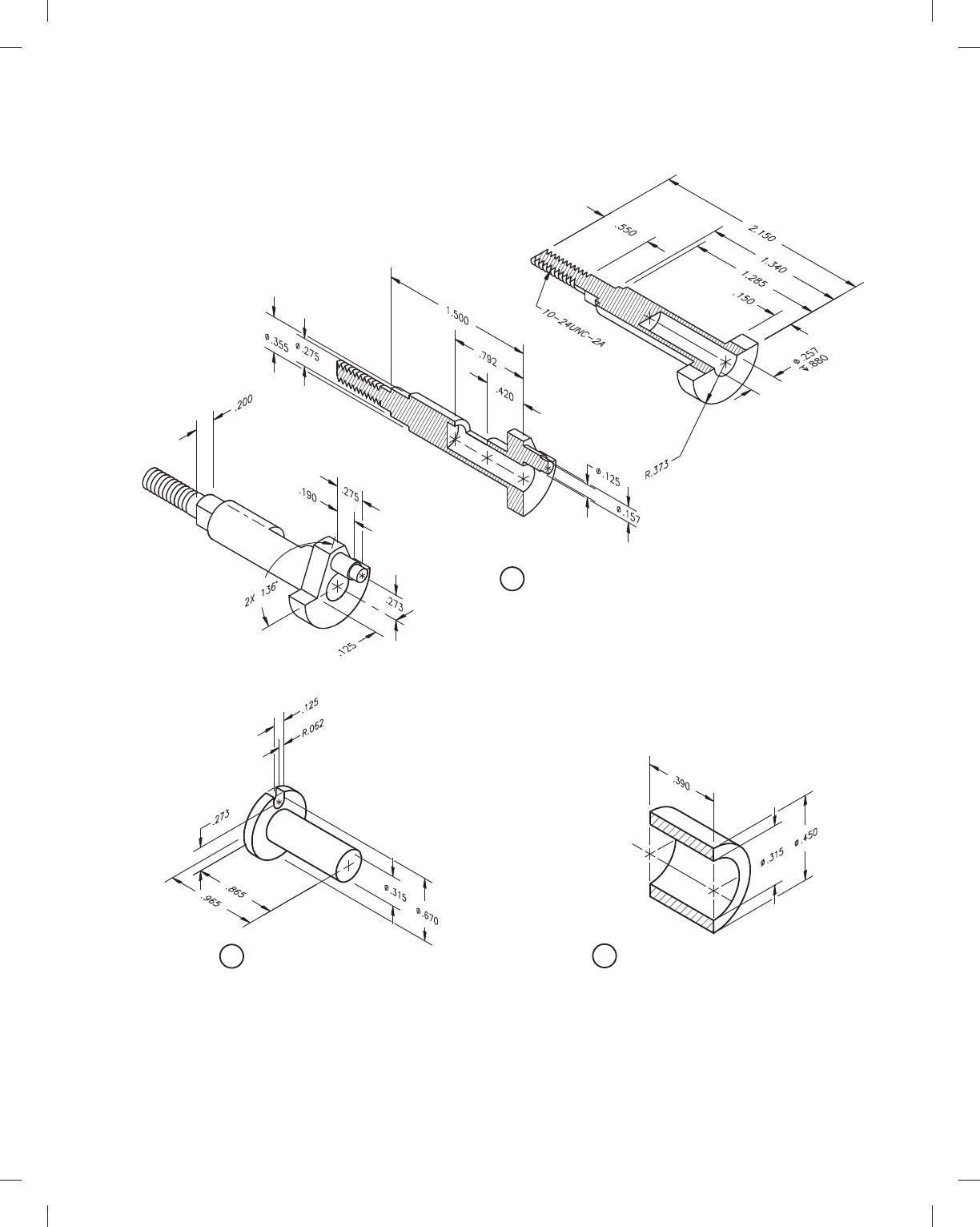
29 FUEL INTAKE ADJUSTER PIN
MATL: SAE 1040
31 PISTON SHAFT
MATL: SAE 1020
32 CRANK ARM
MATL: SAE 1020
33 PISTON PIN
MATL: SAE 1020
34 PISTON
MATL: ALUMINUM
59728_ch15_EOC_ptg01.indd 59 2/3/16 2:24 PM
60
PROBLEM 15.23
(Continued)
35 HEAT SINK
MATL: ALUMINUM
59728_ch15_EOC_ptg01.indd 60 2/3/16 2:24 PM