
CHAPTER 14 PICTORIAL DRAWINGS
AND TECHNICAL ILLUSTRATIONS
PROBLEMS
INSTRUCTIONS
Choose the best axis to show as many featuresof the object as
possible in your axonometric or oblique drawing. Problem as-
signments are presented as engineering designs or sketches and
may not match proper ASME standards.
For axonometric problems—Problems 14.1 through 14.10—
draw isometric, dimetric, or trimetric as assigned. For oblique
problems—Problems 14.11 through 14.17—draw cavalier,
cabinet, or general oblique as assigned. Remember that circular
features are best shown in the front plane of the oblique view.
For perspective problems—Problems 14.18 through
14.25—make a one-, two-, or three-point perspective drawing
as assigned except for Problem 14.18, which should be done as
a one-point perspective view. All objects can be turned at any
desired angle on the picture-plane line for viewing from the
station point, except Problem 14.18, which should be drawn in
the direction indicated.
1. Make a freehand sketch of the object to assist in visualiza-
tion and layout of axonometric and oblique problems.
2. For axonometric and oblique problems, select a scale to fit
the drawing comfortably on an A- or B-size (A4 or A3 metric)
drawing sheet. Use a C- or D-size (A2 or A1 metric) drawing
sheet for drawing an initial layout of the perspective prob-
lems on sketch paper or butcher paper.
59728_ch14_EOC_ptg01.indd 1 2/3/16 2:45 PM
2
3. Dimension axonometric or oblique problems only if
assigned by your instructor. Do not place dimensions on a
perspective view.
4. Perspective objects without dimensions can be measured
directly on the given problem and scaled up as indicated or
assigned.
5. Use an ASME standard border and sheet block, unless
otherwise specified by your instructor.
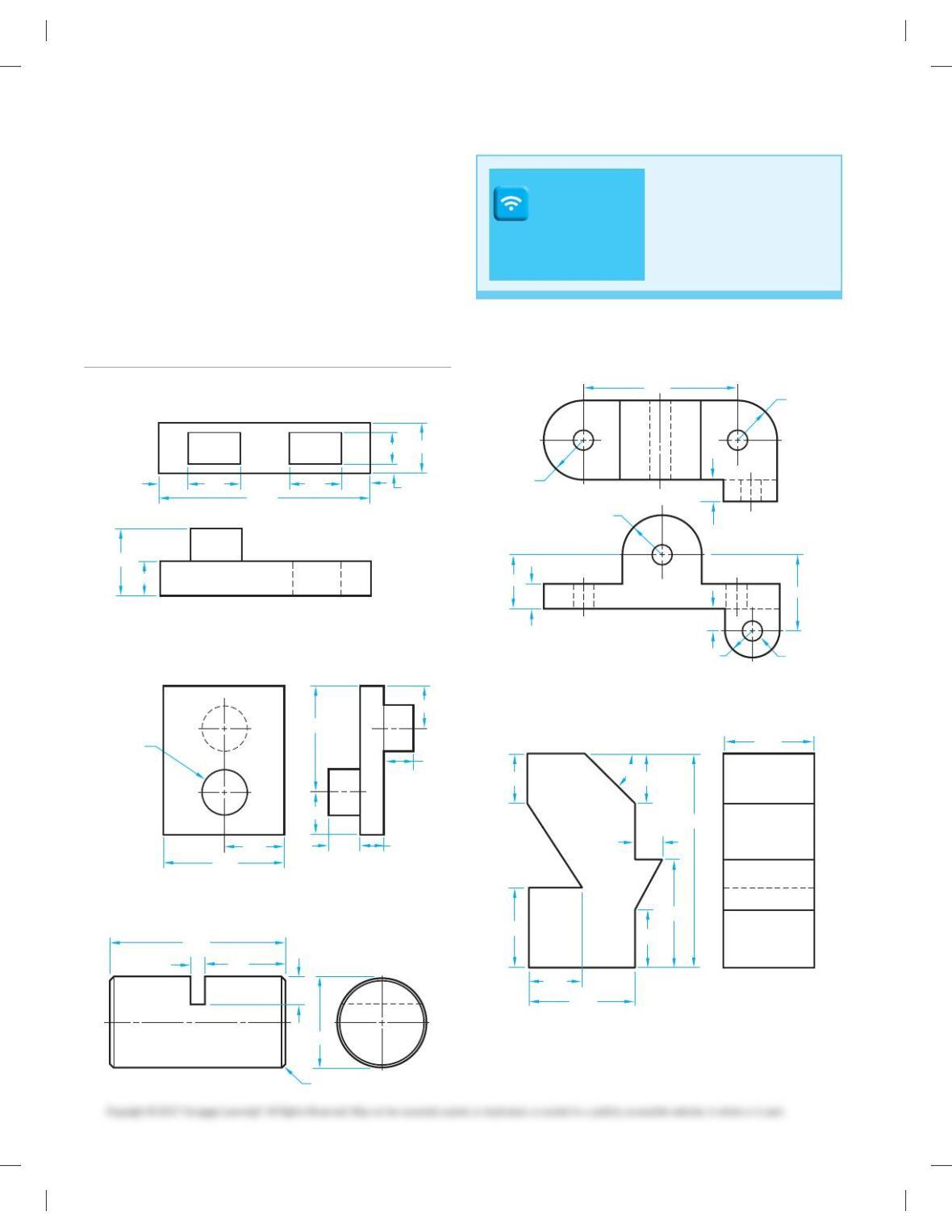
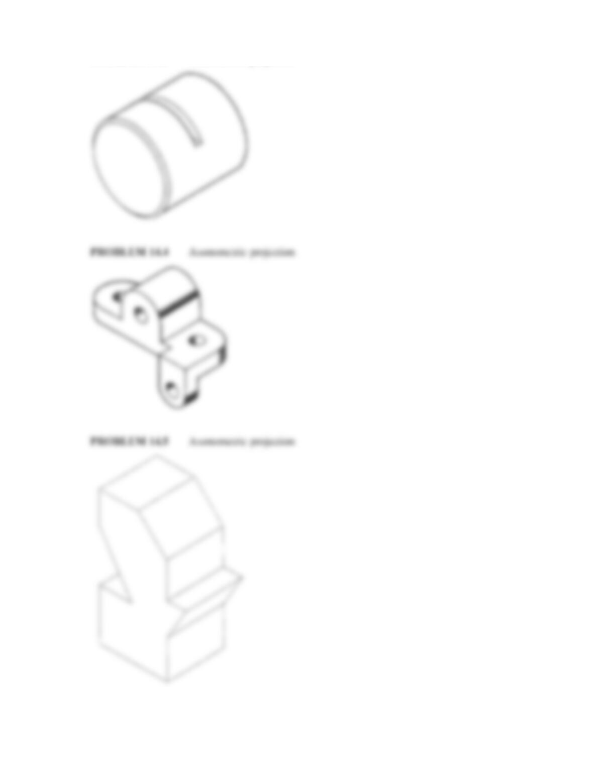
PROBLEM 14.5 Axonometric projection (in.)
.45 .75 .75
.75
.50
.50
.45 .125
3.10
1.00
2.90
1.45
2.50
1.00
1.00
.75 .55
.75
2X
[1.15
4.20
1.91
72
[2.10
2X 458 3.12
.38
135
[18
45
20
20
65
R34
R32
R22
R32
20
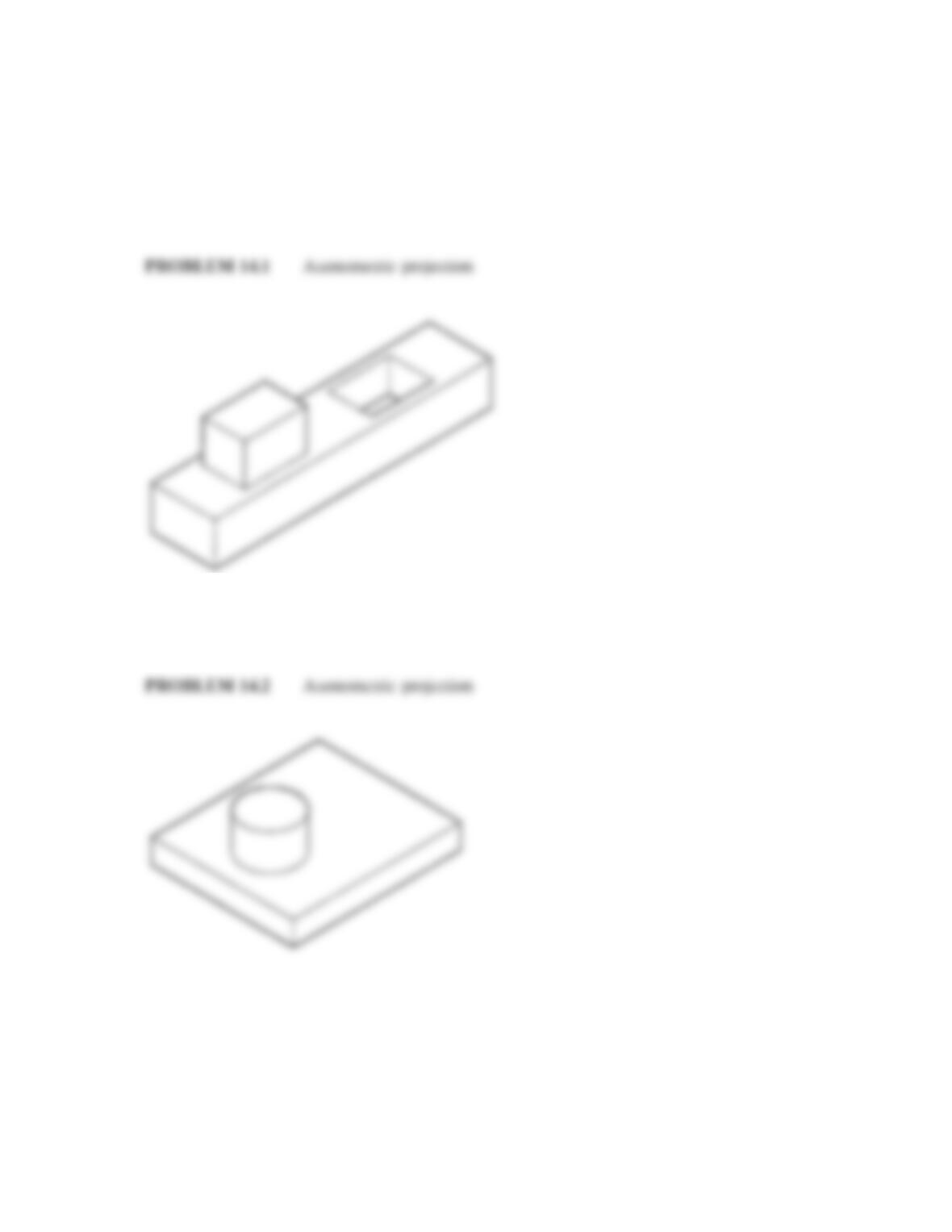
PROBLEM 14.2 Axonometric projection (in.)
PROBLEM 14.3 Axonometric projection (in.)
DRAFTING
TEMPLATES
To access CADD template
files with predefined drafting
settings, go to the Student
Companion Website, select
Student Downloads,
Drafting Templates, and then
the appropriate template file.
Part 1: Problems 14.1 Through 14.5
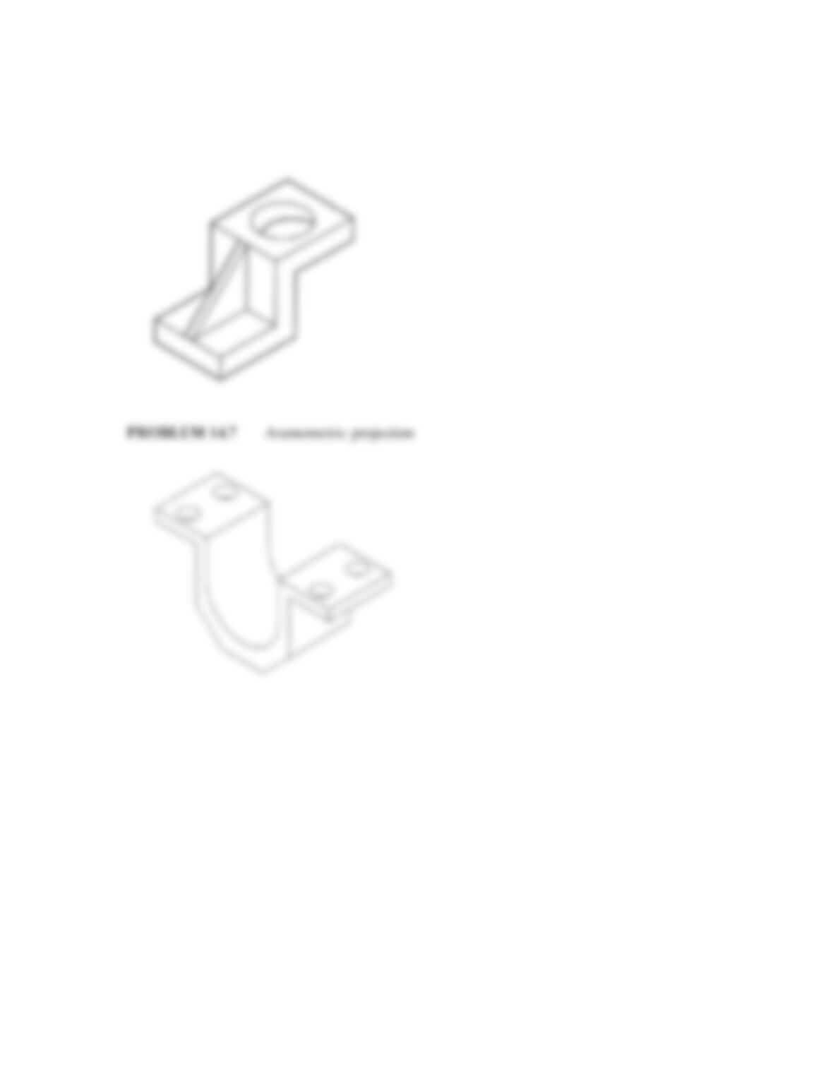
PROBLEM 14.1 Axonometric projection (in.)
PROBLEM 14.4 Axonometric projection (metric)
.90
1.45
.90
458
.50
4.00
1.65
2.00
1.10
1.00
2.00
59728_ch14_EOC_ptg01.indd 2 2/3/16 2:45 PM
3
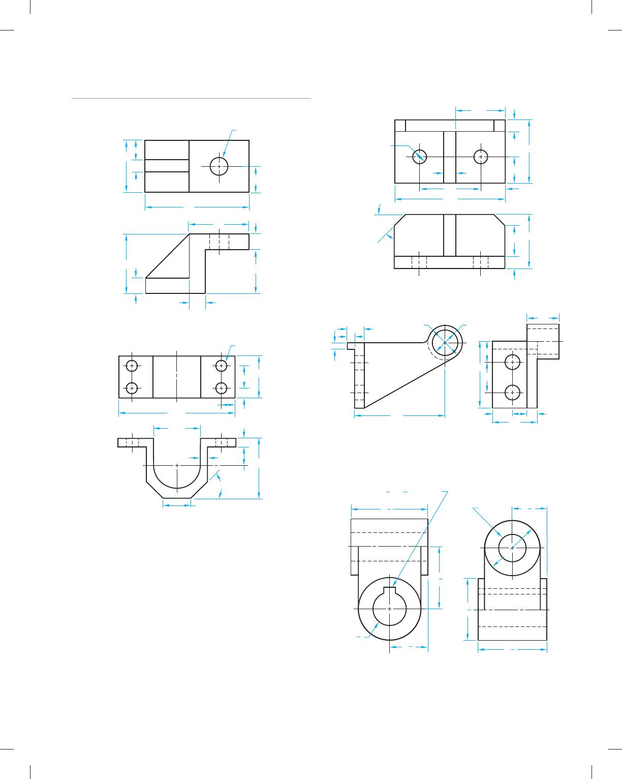
Part 2: Problems 14.6 Through 14.10
PROBLEM 14.6 Axonometric projection (metric)
17
10
88
51
51
22
13
13
13
38
44
∅15
PROBLEM 14.7 Axonometric projection (in.)
.90
.30
1.50
2.15
.25
1.75
4.25
.50
1.00
.25
.64
45°
4X ∅.40
PROBLEM 14.8 Axonometric projection (metric)
12
24
24
64
32
12
55
112
2X ∅15
2X 45°
64
12
50
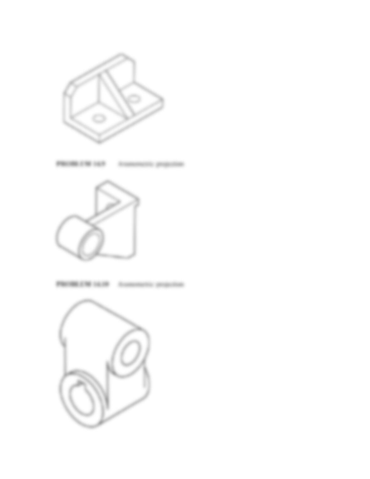
PROBLEM 14.9 Axonometric projection (metric)
40 20
90
43
60
133
182
33
13
13
∅50∅70
64
PROBLEM 14.10 Axonometric projection (in.)
2
KEYWAY
∅1
1
2
1
1
4
∅2
∅2
1
4
∅1
1
4
2
1
4
2
3
4
3
8
3
16
1
3
8
×
59728_ch14_EOC_ptg01.indd 3 2/3/16 2:45 PM
4
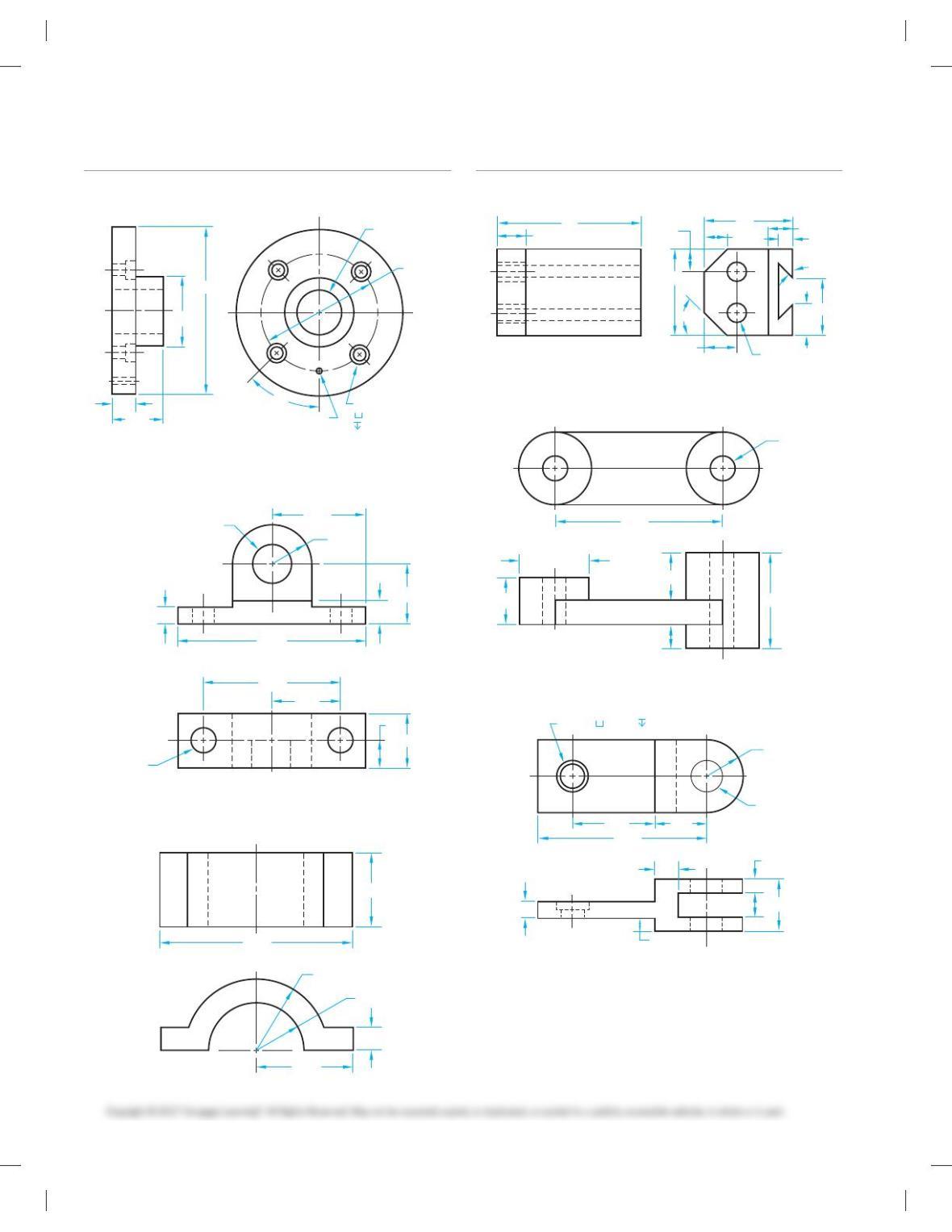
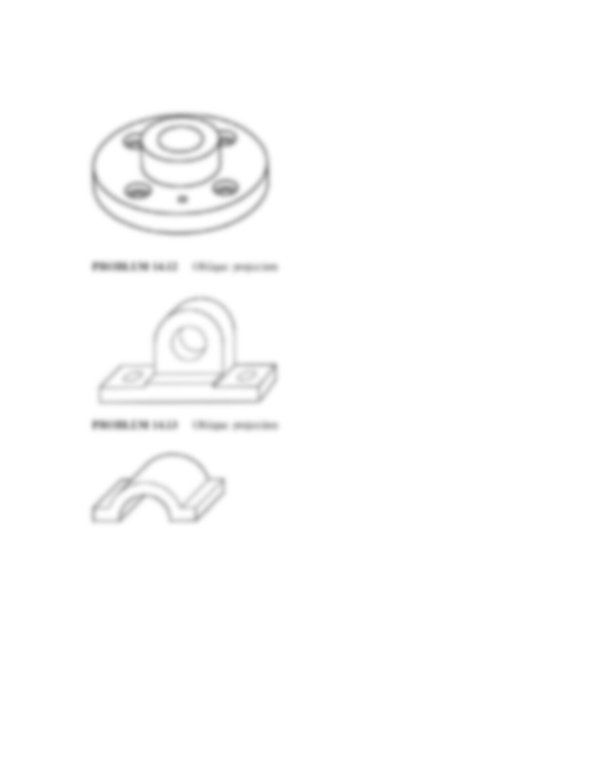
PROBLEM 14.13 Oblique projection (in.)
D
2.62
1.125
1.123 R1.12
.50
5.24
3.76
1.88
.75
1.50
1.62
.62
2X D.65
[1.00
[2.76
[.18
[1.75
[3.90
4X [.34
458
.54
1.24 [.56
.19
Part 3: Problems 14.11 Through 14.13
PROBLEM 14.11 Oblique projection (in.)
PROBLEM 14.12 Oblique projection (in.)
Part 4: Problems 14.14 Through 14.17
PROBLEM 14.14 Oblique projection (metric)
38
57
45°
45°
13
18
58
15
15
20
19
2X ∅12
94
19
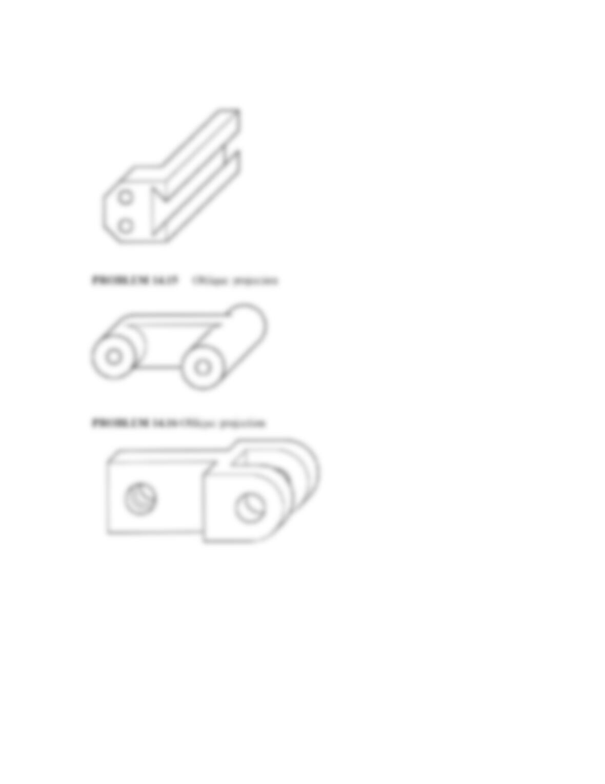
PROBLEM 14.15 Oblique projection (in.)
2X ∅.50
2X ∅3.00
3.50
1.00
1.00
2.00
.50
PROBLEM 14.16 Oblique projection (in.)
R1.00
∅.65 ∅.90
2X ∅.85
4.70
.24
.48
.52 .39
.64 1.42
.40
2.30 1.40
R.150
R.100
.50
2.00
4.00
1.55
59728_ch14_EOC_ptg01.indd 4 2/3/16 2:45 PM
5
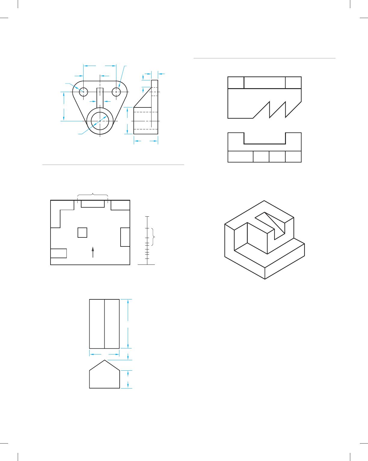
PROBLEM 14.17 Oblique projection (in.)
∅
∅1.94
2X ∅.58
2.30
1.15
R.80
2.12
1.75
.50
.50
.48
1.130
1.126
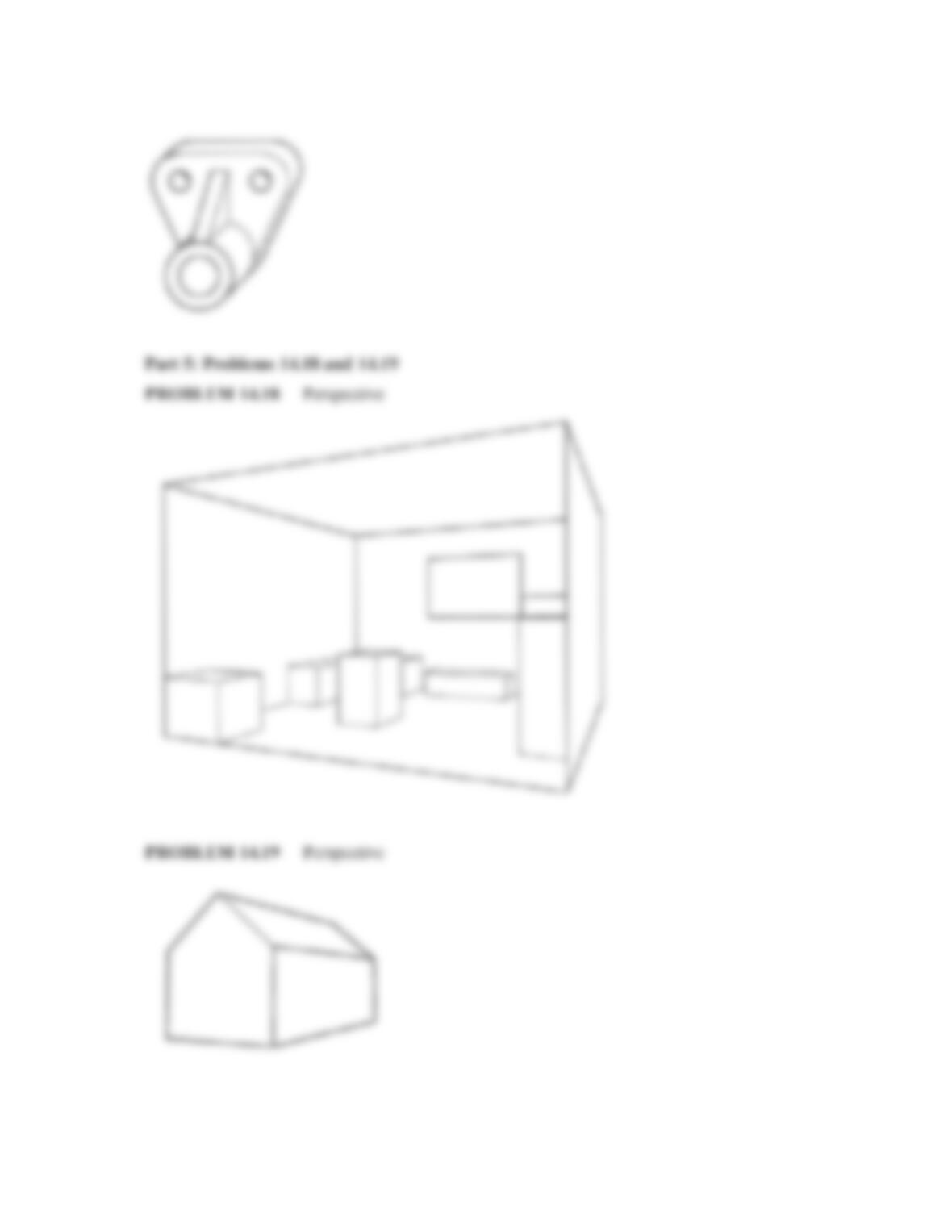
Part 5: Problems 14.18 and 14.19
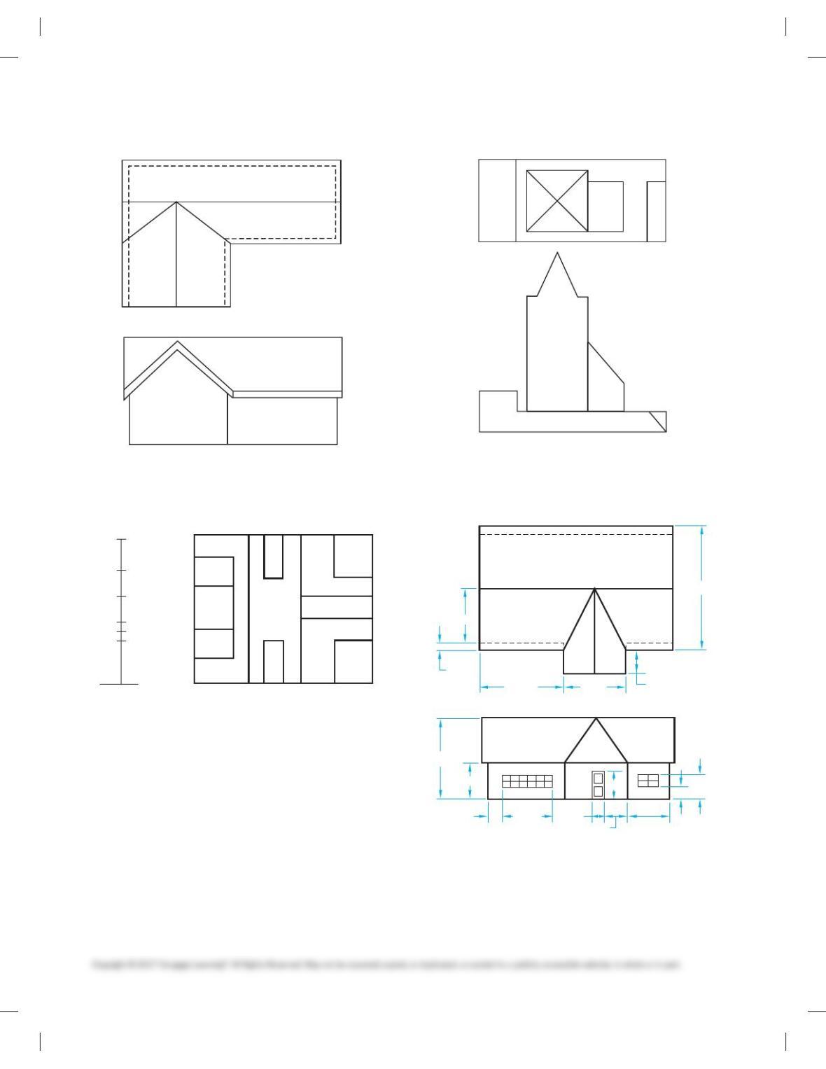
PROBLEM 14.18 Perspective
PLAN
VIEW
ELEVATION
WINDOW
WINDOW
CEILING
D
D
C
C
A
A
B
B
F
F
E
E
PROBLEM 14.19 Perspective
53′
11′
18′
26′
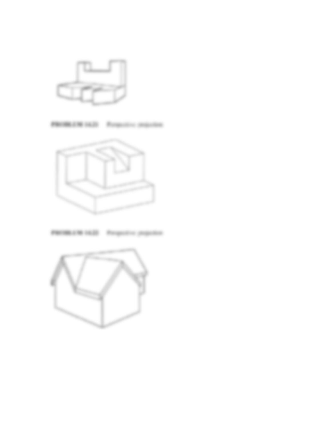
Part 6: Problems 14.20 Through 14.25
PROBLEM 14.20 Perspective
MEASURE AND INCREASE 2X
PROBLEM 14.21 Perspective
MEASURE AND INCREASE 2X
59728_ch14_EOC_ptg01.indd 5 2/3/16 2:45 PM
6
PROBLEM 14.22 Perspective
MEASURE AND INCREASE 2X
PROBLEM 14.23 Perspective
PLAN
ELEVATIONS
D
E
F
C
B
DD
C
C
A
A
B
B
F
F
F
F
E
MEASURE AND INCREASE 3X
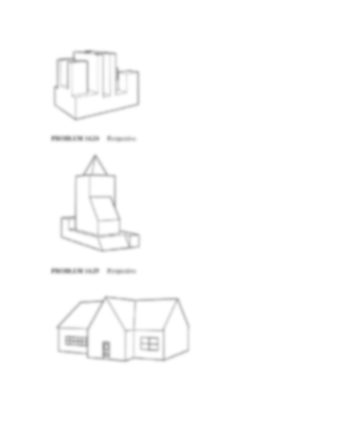
PROBLEM 14.24 Perspective
MEASURE AND INCREASE 3X
PROBLEM 14.25 Perspective
13’–0″
2’–0″
20’–0″ 15’–0″ 6’–0″
12’–0″4’–0″
20’–0″
9’–0″
6’–0″
3’–0″
10’–0″
3’–0″
6’–10″
7’–0″
30’–0″
59728_ch14_EOC_ptg01.indd 6 2/3/16 2:45 PM
7
Part 7: Problems 14.26 and 14.27
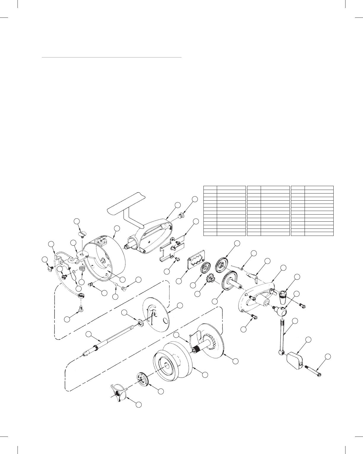
ADVANCED PROBLEM 14.26
Go to the Chapter 15, Working Drawings, problems. These prob-
lems are presented as assembly drawings, exploded isometric
assembly drawings, parts lists, and dimensioned isometric detail
drawings. An assembly drawing is a drawing that shows how the
parts of a product go together. A detail drawing is a drawing of an
individual part that contains all of the views, dimensions, and
specifications necessary to manufacture the part. A parts list
identifies every part in the assembly and is a tabulation of all
parts and materials used in a product. These drawing types are
described in detail in Chapter 15, Working Drawings. These fun-
damentals are not important at this time.
From the problems in Chapter 15, Working Drawings, select
one or more of the problems or as assigned by your instructor.
Using the drawings and information provided in the assigned or
selected problem, create an exploded isometric technical illus-
tration, with trails, and identification numbers correlated to a
parts list. Dimensions are not required. There is no recommended
ITEM NO.
1
2
3
4
5
6
7
8
9
10
11
12
13
HOUSING
LUBE PORT SCR
GUIDE
GUIDE SCREW
AXLE SLIDE
PIVOT GEAR
TRANSFER GEAR
PINION GEAR
DRIVE GEAR
ANTI REVERSE SPG
ANTI REVERSE
COVER PLATE
COVER SCREW
ITEM NO.
14
15
16
17
18
19
20
21
22
23
24
25
26
SHANKE SCREW
SHANKE SHAFT
SHANKE HANDLE
HANDLE KNOB
HANDLE SCREW
ROTATING BODY
BAIL SCREW
BAIL
TRIP LEVER
LEVER SCREW
TRIP SPRING SCR
TRIP SPRING
BAIL SCREW
ITEM NO.
27
28
29
30
31
32
33
34
35
36
37
38
39
BAIL SPRING
WEIGHT SCREW
COUNTER WEIGHT
ROLLER LINE
LINE SCREW
BAFFLE PLATE
HEX NUT
AXLE
SPINDLE
CLICK SPRING
SPOOL
BRAKE SPRING
DRAG KNOB
PART NAME
PART NAME
PARTS LIST
SPINNING REEL
PART NAME
11
10
7
4
5
6
26
27
30
25
8
9
39
38
37
28
29
35
36
33
31
32
34
13
3
2
1
12
14
15
16
17
18
24
23
22 21
20
19
solution. and these problems are considered advanced. In addi-
tion or alternately, use your 3-D modeling program to create solid
models of the selected parts and assembly. Confirm the preferred
approach with your instructor.
ADVANCED PROBLEM 14.27
Find a product of your choice or as assigned by your instructor.
The product should have at least four parts and must be some-
thing that you can easily disassemble without destroying. This is
entirely your responsibility. Using the selected product, create an
exploded isometric technical illustration, with trails, and identi-
fication numbers correlated to a parts list. You need to measure
the parts to create the drawings. Measurements should be ac-
curate, but exact measurements are not required, because the
drawings will not be dimensioned. There is no recommended
solution, and these problems are considered advanced. In addi-
tion or alternately, use your 3-D modeling program to create
solid models of the selected parts and assembly. Confirm the
preferred approach with your instructor. The following is an
example of an exploded isometric assembly drawing:
59728_ch14_EOC_ptg01.indd 7 2/3/16 2:45 PM

8
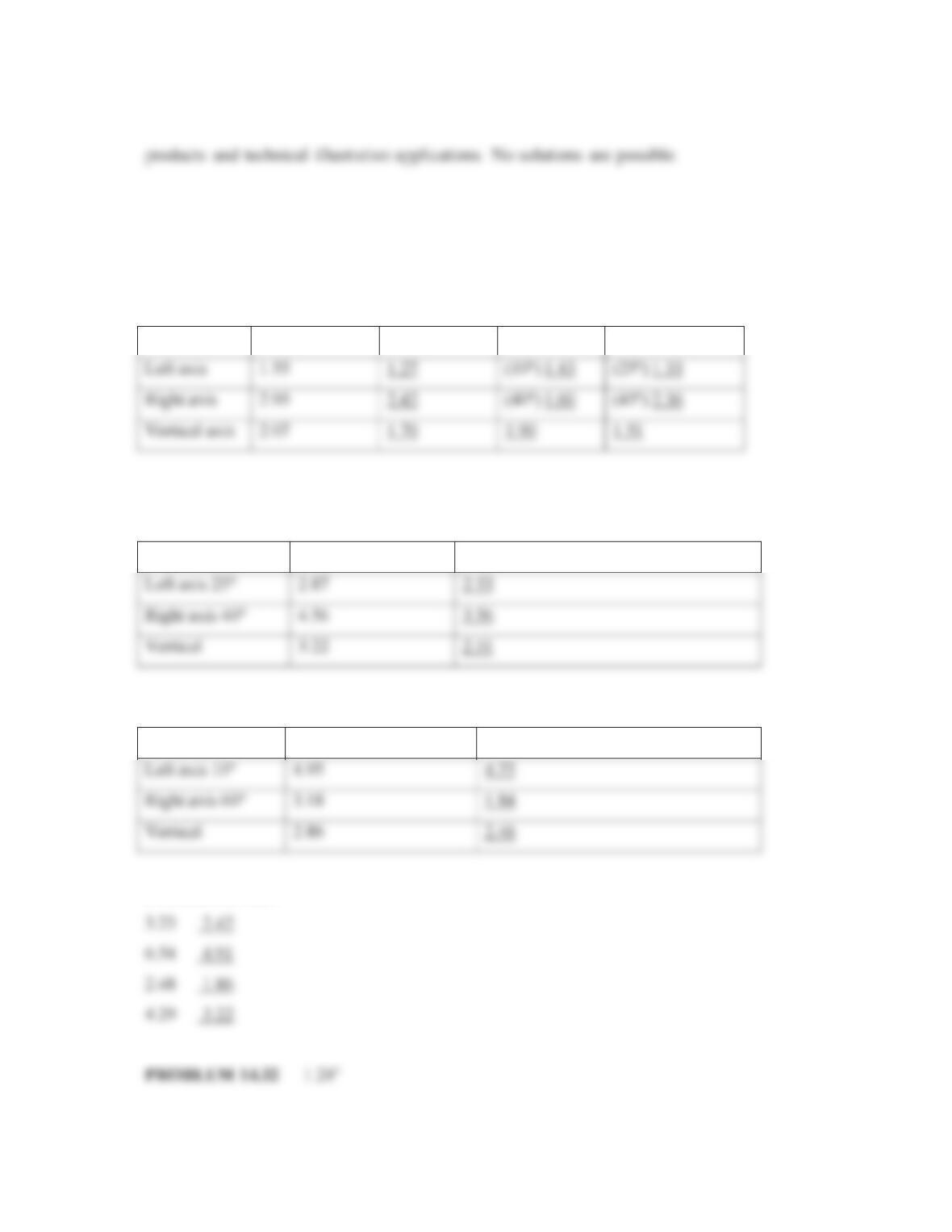
MATH PROBLEMS
Part 8: Problems 14.28 Through 14.32
PROBLEM 14.28 Provide the measurements required to con-
struct isometric, dimetric, and trimetric projections using the
following actual dimensions of the parts. The dimetric and tri-
metric angles are given.
DIMENSION ISOMETRIC DIMETRIC TRIMETRIC
Left axis 1.55 _____ (108)_____ (258)_____
Right axis 2.95 _____ (408)_____ (458)_____
Vertical axis 2.07 _____ _________ _________
PROBLEM 14.29 Provide the dimetric projection measure-
ments for an object with the following actual dimensions. The
left and right axis angles are given.
DRAWING
DIMENSION MEASUREMENT
Left axis 258 2.87 _______
Right axis 408 4.46 _______
Vertical 3.22 _______
PROBLEM 14.30 Provide the trimetric projection measure-
ments for an object with the following actual dimensions. The
left and right axis angles are given.
DRAWING
DIMENSION MEASUREMENT
Left axis 108 4.95 _______
Right axis 608 3.18 _______
Vertical 2.86 _______
PROBLEM 14.31 If a 3/4 scale is used to draw the receding
axis of a general oblique object, how long would you draw the
following dimensions on the receding axis?
3.23 ____
6.54 ____
2.48 ____
4.29 ____
PROBLEM 14.32 If a cylindrical object has a diameter of
3.75 in., what is the approximate width of the block shading
that should be applied to it?
59728_ch14_EOC_ptg01.indd 8 2/3/16 2:45 PM
190
Chapter 14
Pictorial Drawings and Technical Illustrations
Solutions to End-of- Chapter Problems
Part 1: Problems 14.1 Through 14.5
191
PROBLEM 14.3 Axonometric projection
192
Part 2: Problems 14.6 Through 14.10
PROBLEM 14.6 Axonometric projection
193
PROBLEM 14.8 Axonometric projection
194
Part 3: Problems 14.11 Through 14.13
PROBLEM 14.11 Oblique projection
195
Part 4: Problems 14.14 Through 14.17
PROBLEM 14.14 Oblique projection
196
PROBLEM 14.17 Oblique projection
197
Part 6: Problems 14.20 Through 14.25
PROBLEM 14.20 Perspective
198
PROBLEM 14.23 Perspective
199
Part 7: Problems 14.26 and 14.27
ADVANCED PROBLEMS 14.26 AND 14.27 Solutions vary depending on selected
Math Problem Solutions
Part 8: Problems 14.28 Through 14.32
PROBLEM 14.28
DIMENSION ISOMETRIC DIMETRIC TRIMETRIC
PROBLEM 14.29
DIMENSION DRAWING MEASUREMENT
PROBLEM 14.30
DIMENSION DRAWING MEASUREMENT
PROBLEM 14.31