CHAPTER 13 GEOMETRIC
DIMENSIONING AND TOLERANCING
PROBLEMS
INSTRUCTIONS
From the selected problems, determine which views and
dimensions should be used to detail the part completely. Include
all dimensions needed using unidirectional dimensioning.
1. Make a multiview sketch of the selected problem as close to
correct proportions as possible. Be sure to indicate where
you intend to place the dimension lines, extension lines,
arrowheads, geometric tolerancing symbols, and hidden
features to help you determine the layout for your final
drawing.
2. Using your sketch as a guide, make an original multiview
drawing on an adequate size ASME-standard drawing sheet
with border and sheet blocks. Use an appropriate scale.
3. When using solid modeling software, create the solid model
using the given geometry and confirm the accuracy of the
given engineering information as you proceed. Consult with
your instructor or supervisor if you discover problems with
the geometry and revise the drawings as needed to make the
geometry accurate. Use your completed part solid models
to develop fully dimensioned 2-D detail drawings. Place a
3-D model in the upper left corner of the drawing for use as
a visualization aid.
4. Include the following general notes at the lower left corner
of the sheet .5 in. each way from the corner border lines:
NOTES:
1. DIMENSIONS AND TOLERANCES PER ASME Y14.5-2009.
2. REMOVE ALL BURRS AND SHARP EDGES.
Additional general notes can be required, depending on the
specifications of each individual assignment. Use the following
for tolerances for unspecified inch values. A tolerance block is
recommended as described in Chapter 2.
Unspecified Tolerances
Decimals In.
X6.1
XX 6.01
XXX 6.005
ANGULAR 630
FINISH 125 µin.
For metric drawings, provide a general note that states
TOLERANCES FOR UNSPECIFIED DIMENSIONS COMPLY
WITH ISO 2768-m. Provide a general note that states SURFACE
FINISH 3.2 µm UNLESS OTHERWISE SPECIFIED.
Each problem assignment is given as an engineer’s layout to
help simulate actual drafting conditions. Dimensions and views
on engineers’ layouts may not be placed in accordance with
acceptable standards. You need to review the chapter material
carefully when preparing the layout sketch. In some problems,
the engineer’s layout assumes certain information, such as the
symmetry of a part or the alignment of holes. You need to place
enough dimensions or draw lines between features to dimension
the part fully.
DRAFTING
TEMPLATES
To access CADD template files
with predefined drafting
settings, go to the Student
Companion Website, select
Student Downloads, Drafting
Templates, and then the
appropriate template file. Use
the templates to create new
designs, as a resource for
drawing and model content, or
for inspiration when developing
your own templates. The
ASME-Inch and ASME-Metric
drafting templates follow
ASME, ISO, and related
mechanical drafting standards.
Drawing templates include
standard sheet sizes and
formats and a variety of
appropriate drawing settings
and content. You can also use a
utility such as the AutoCAD
DesignCenter to add content
from the drawing templates to
your own drawings and
templates. Consult with your
instructor to determine which
template drawing and drawing
content to use.
59728_ch13_EOC_ptg01.indd 8 2/3/16 2:21 PM
Part 1: Problems 13.1 Through 13.15
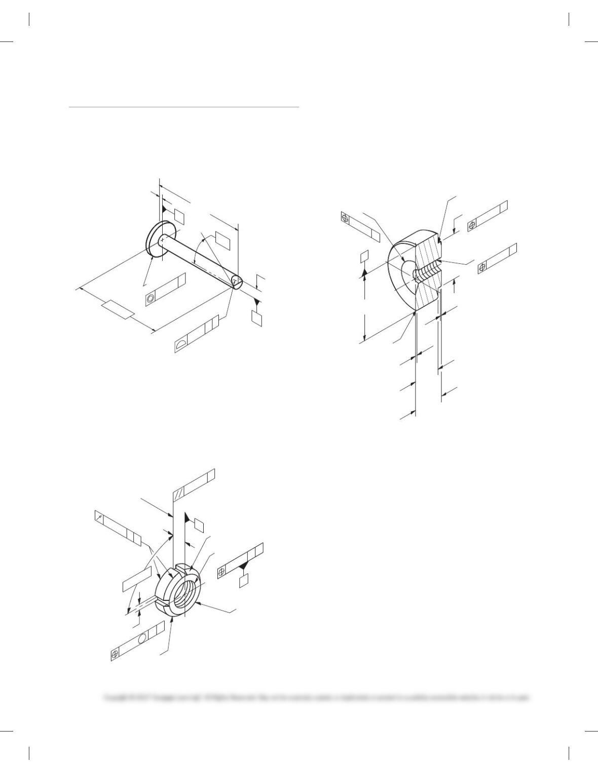
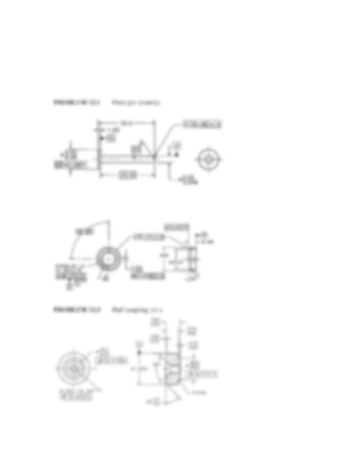
PROBLEM 13.1 Geometric tolerancing (metric)
Part Name: Flow Pin
Material: Bronze
Finish: Finish all over 0.20 mm.
25.5
24.45
1.05
B
A
0.08 AB
3.050
3.048
Ø0.08 A
9.02
8.98
35
8
Ø
Ø
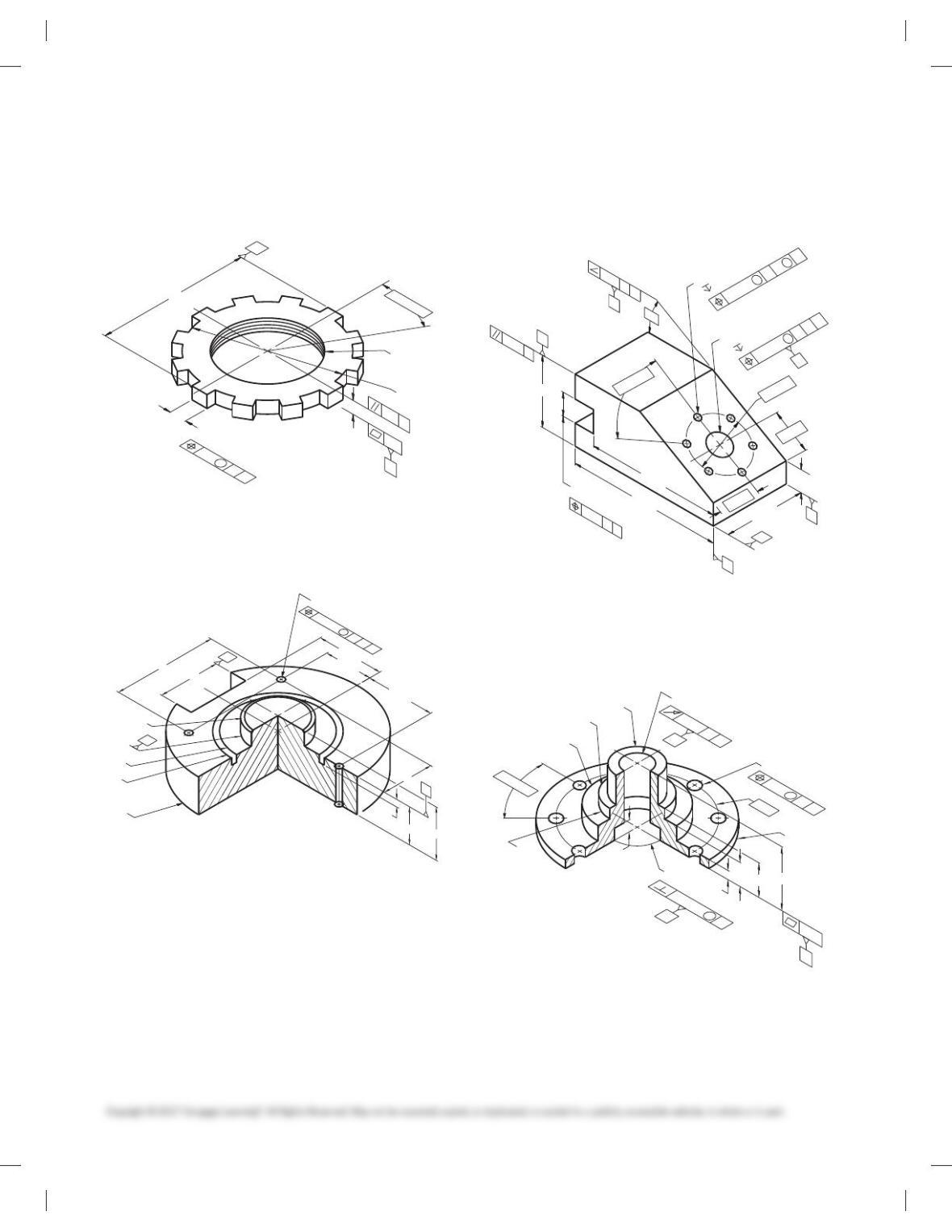
PROBLEM 13.2 Geometric tolerancing (metric)
Part Name: LN2 Test Pump Lock Nut
Material: AMS 5732
Additional General Notes: Mark per AS478 Class D with
1193125 and applicable dash number.
Finish all over 1.6 µm.
3.302
3.298
0.25
M
AB
4X 908
Ø28 Ø23.57
508 (FROM VERT)
M16X2-5H LH
2X 458 X 0.76
B
A
Ø0.05
MINOR
DIA B
A
0.025 A
0.127 AB
8.745
CENTER OF
SLOT AT BACK
SURFACE
4X
PROBLEM 13.3 (in.)
Part Name: Half Coupling
Material: 1.250 6061-T6 aluminum
SPECIFIC INSTRUCTIONS: Provide MMC material condition
after position tolerance except for RFS at threads.
Problem based on original art courtesy TEMCO.
.580
.560
.015
.045
.510
Ø
Ø1.250
.865
.850
Ø.010 A
A
.005
.490
.025
4X 47
8
43
8
.250-18 NPTF
Ø.005 A
.641
.609
Ø.010 A
R.015
2X
Ø
59728_ch13_EOC_ptg01.indd 9 2/3/16 2:21 PM
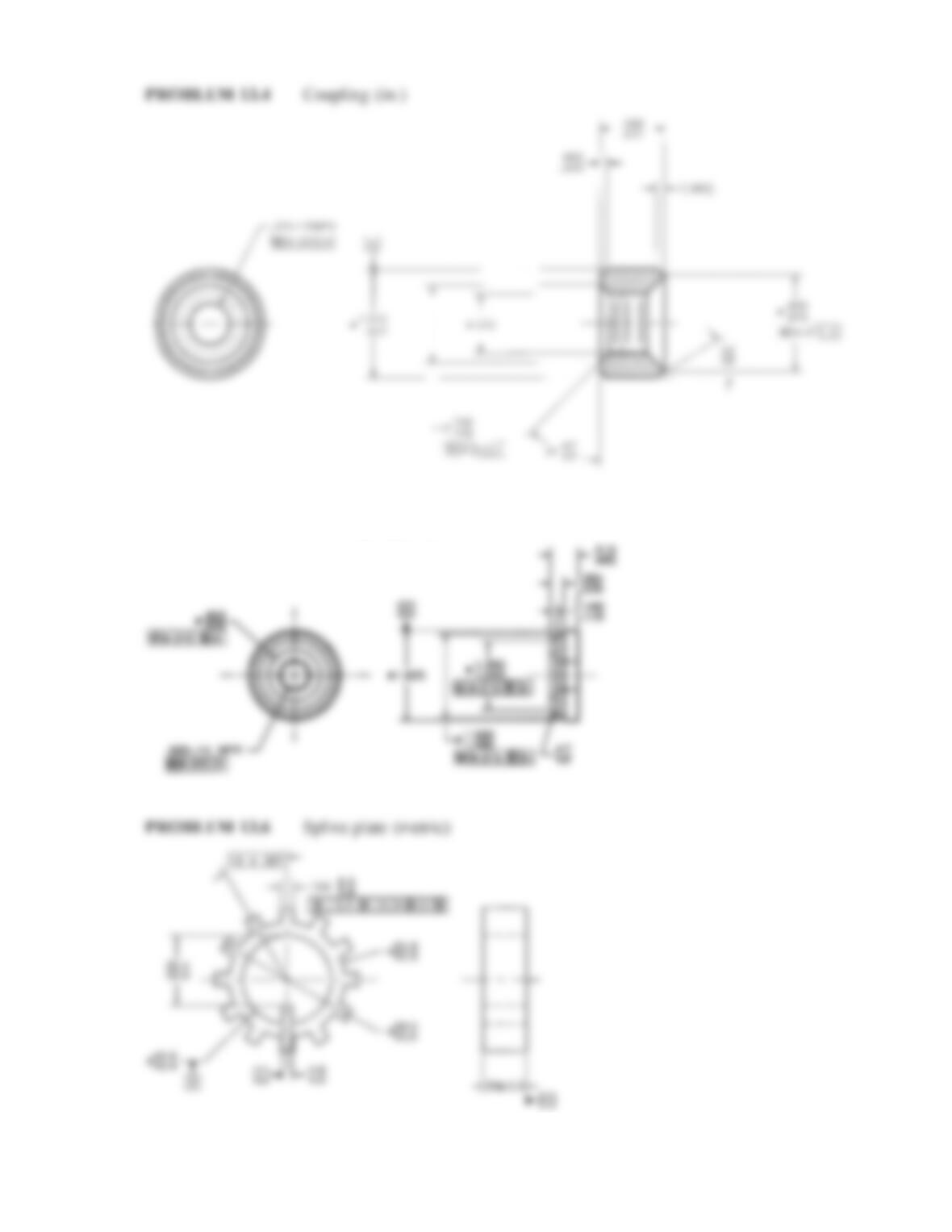
PROBLEM 13.4 (in.)
Part Name: Coupling
Material: AISI 1010, Killed
SPECIFIC INSTRUCTIONS: Provide MMC material condition
after position tolerance except for RFS at threads.
Problem based on original art courtesy TEMCO.
Ø1.010
.990
Ø.890
.870
Ø.010 A
.728
.708
Ø.010 A
.593
.062
( .080 )
.531
.000
Ø.562
Ø32
8
28
8
47
8
43
8
3X
A
.375-18 NPTF
Ø.005 A
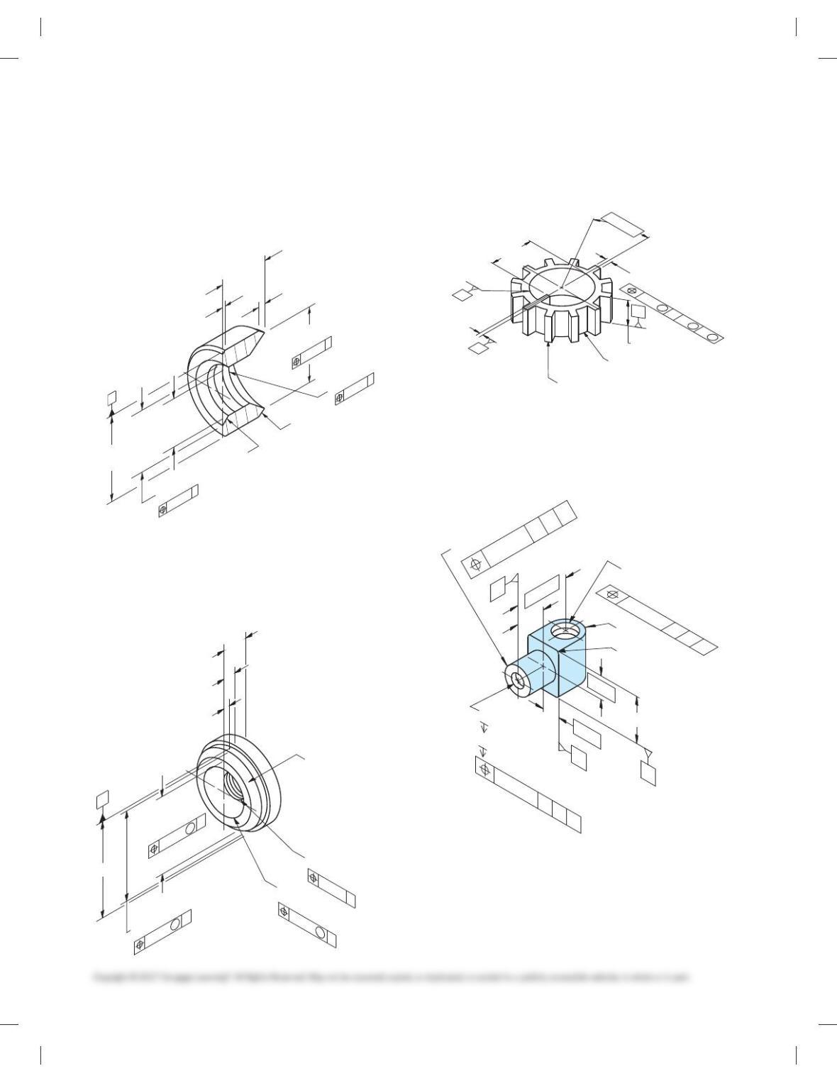
PROBLEM 13.5 (in.)
Part Name: Half Coupling
Material: Ø 1.625 6061-T6511
Problem based on original art courtesy TEMCO.
Ø1.625
Ø1.500
1.480
1.260
Ø
Ø.015
1.240
A
M
A
.500-14 NPTF
47
8
43
8
.922
.920
ØTAPER TO MAJOR
DIAMETER
A
Ø.005 A
A
.265
.235
.515
.485
.140
.110
Ø.015
M
Ø.005
M
PROBLEM 13.6 (metric)
Part Name: Spline Plate
Material: SAE 3135
4.0
4.8
6.0
5.8
32.0
32.4
52.8
Ø
Ø
Ø52.5
65.6
66.0
40.6
40.4
12X 30
8
C
B
12X
A
20.00.3
0.4 B
AC
M
M
M
PROBLEM 13.7 (in.)
Part Name: Nut
Material: No. 10 Bronze
Ø.312
1.00
3/8-16 UNC-2B
.75
1.187
Ø.390
Ø.014
1/2-10 ACME-LH
.6246
Ø
Ø.014
.6243
4X .063
R.375
C
A
B
CBA
.375
1.000
.500
.625
Ø.014 CBA
CB
A
59728_ch13_EOC_ptg01.indd 10 2/3/16 2:21 PM
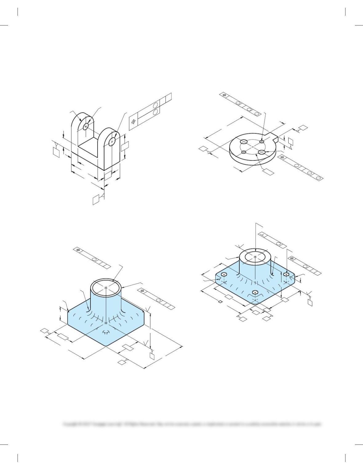
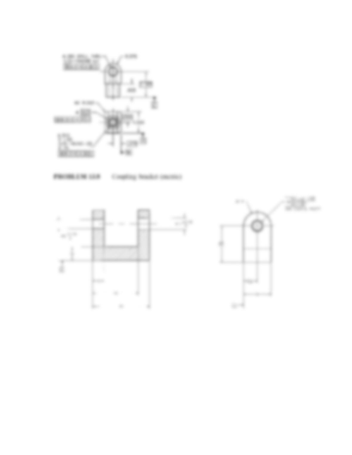
PROBLEM 13.8 (metric)
Part Name: Coupling Bracket
Material: SAE 4310 Steel
Ø8 +0.15
0
Ø10 +0.15
0
Ø 0.2
Ø 0.1
TWO COAXIAL HOLES
2X R
B
A
32
12
24
50
40
10
12
BA
M
M
PROBLEM 13.9 (in.)
Part Name: Thrust Washer
Material: SAE 5150
R.25
Ø1.875 -.000
+.008
63
63
2.50
2.50
5.00
5.00
.875
C
A
B
2.625
Ø.008 CBA
L
12X R.12
Ø1.625 -.005
+.000
Ø.005 BC
A
L
PROBLEM 13.10 (metric)
Part Name: Spacer
Material: SAE 4310
16
2X Ø10±0.25
76.0 -0.4
0
SEP. REQT
Ø66 -0.4
0
0
-0.4
C
B
Ø36
A
8
SEP. REQT
2X Ø6±0.2
Ø.02 BC
A
MMM
Ø.04 BC
A
MMM
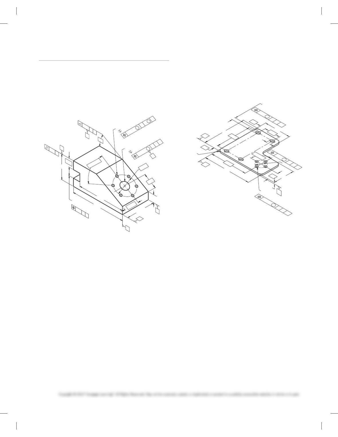
PROBLEM 13.11 (metric)
Part Name: Bearing Support
Material: SAE 1040
1.6
3.2
Ø0.01 A
4X Ø9
32.00
Ø32.16 THRU
+0.2
0
50
70
10
10
16
A
B
C
C
AB
70
M
Ø0.4
M
90
Ø50
45
4X R10
R5
R5
59728_ch13_EOC_ptg01.indd 11 2/3/16 2:21 PM
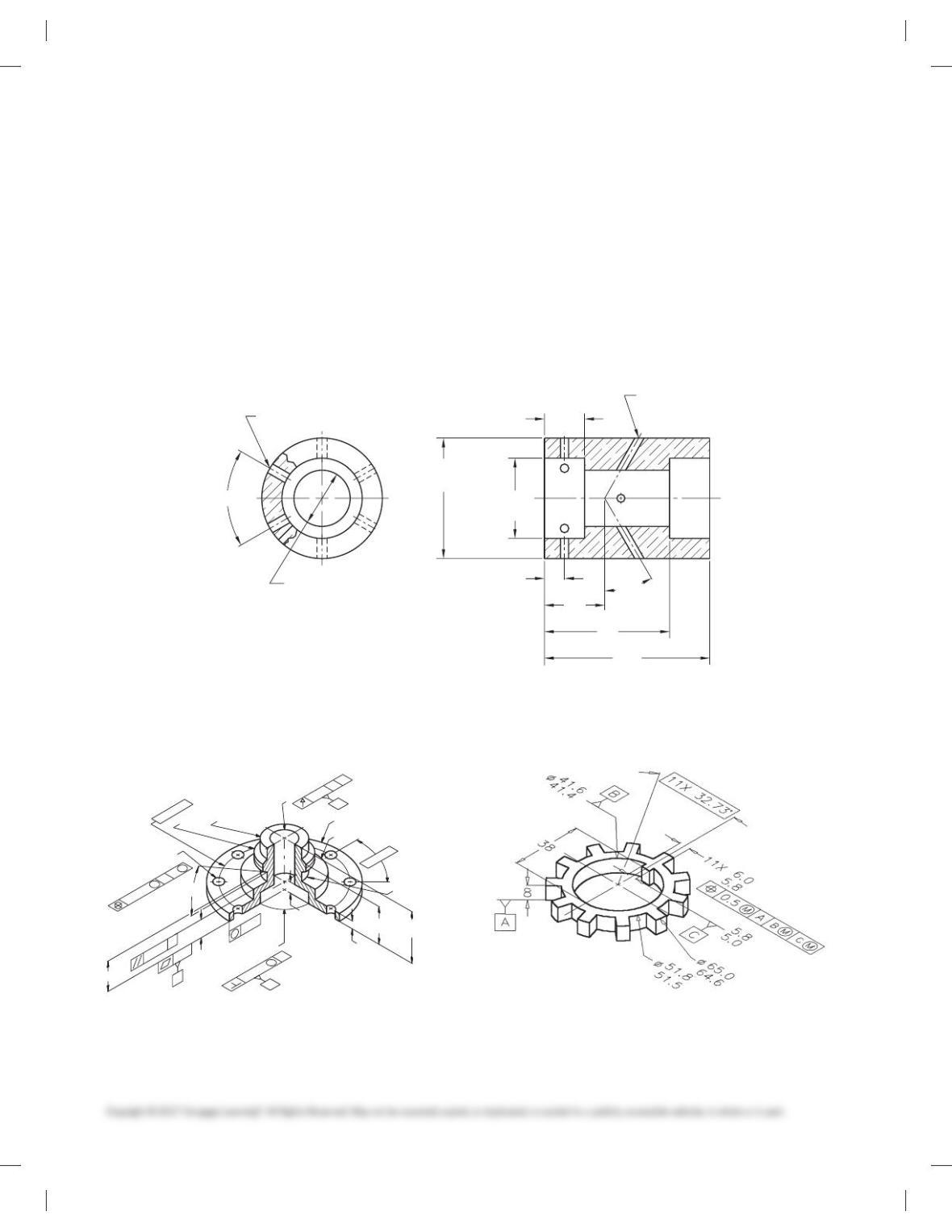
PROBLEM 13.12 (metric)
Part Name: Lock Nut
Material: SAE 3130
Ø112
12X 8 -0.4
0
12X 308
B
M64 X 6
95.25
A
9.5
0.6 B
A
M
0.4
A
0.8
PROBLEM 13.13 (in.)
Part Name: Cover Plate
Material: Phosphor bronze
2.063
Ø2.000
Ø3.125
Ø3.500
Ø6.000
45
8
X .062
.250
C
B
3.500
1.625
1.750
A
2.313
1.750
2.250
1.250
3X Ø.250-.255
CB
A
M
Ø.001
PROBLEM 13.14 (in.)
Part Name: Angle Support Mounting
Material: SAE 3110
Ø.718
-.000
+.008
1.100
2.150
E
C
Ø.007 E
H
G
12-28 UNF-2B
.625
H
6X 60
8
D
F
E
C
G
.718
.008
-.005
+.000
2.500
.688
1.188
Ø1.750
4.750
4.125
1.250
30
8
D
.010
MM
Ø.005 F
E
G
M
E
D
.005
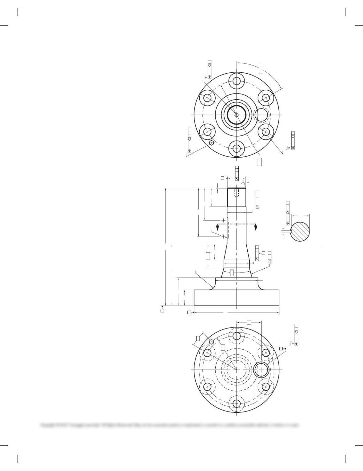
PROBLEM 13.15 (metric)
Part Name: Hub
Material: SAE 3310
36
34
Ø
8X Ø8.334
Ø88
Ø110
Ø20
458 X 0.3
M42 X 4.5
Ø60
R4
8X 458
A
Ø0.065 A
M
0.03
M
C
A
C
A
0.15
Ø0.1
B
8
42.5
23
6
16
C
32.0
32.5
Ø
59728_ch13_EOC_ptg01.indd 12 2/3/16 2:21 PM
Part 2: Problems 13.16 Through 13.23
PROBLEM 13.16 Geometric tolerancing (metric)
Part Name: Fixture MIBRDA—1265
Material: SAE 4320
Harden: Brinell 200–240
Additional General Notes
1. Finish all over 0.80 mm.
Ø18
-0
+0.5
28
55
E
C
Ø0.3 E
H
G
M5 X 0.8-6H
16
H
6X 60º
D
F
E
C
G
0.5
17.85
18.00
63.5
16.5
30
Ø45
120
105
31.75
30º
D
0.5
MM
Ø0.2 F
E
G
M
E
D
0.2
18.5
PROBLEM 13.17 Geometric tolerancing (metric)
Part Name: Mounting Bracket
Material: Stainless steel
Additional General Notes:
1. All fillets and rounds R24.
2. Finish all over 1.6 mm.
40
30
80
+0.6
0
F
4X Ø
20.5
20.0
0
+0.4
F
4X 24
6X R20
4X 32
F
E
D
0.5 E
D
M
M
1.4 E
D
4X 90º
360
280
325 265
200
120
10
Ø75
160
F
Ø0.2 E
D
M
59728_ch13_EOC_ptg01.indd 13 2/3/16 2:21 PM
PROBLEM 13.18 Geometric tolerancing (metric)
Part Name: Oscillator Housing
Material: Phosphor bronze
Additional General Notes:
1. Finish all over 0.80 µm.
SPECIFIC INSTRUCTIONS:
Use the following engineer’s notes to complete the geometric
tolerancing of the Oscillator Housing:
■ Establish datum A with three equally spaced datum target
points at each end of the [28.1-28.0 cylinder.
■ Establish datum B at the left end surface.
■ Make the bottom surfaces of the 2X [40.2–40.0 features per-
pendicular to datum A by 0.06.
■ Provide a cylindricity tolerance of 0.3 to the outside of the
part.
■ Make the 2X [40.2–40.0 features concentric to datum A by
0.1.
■ Locate the 6X [6 holes with reference to datum A at MMC
and datum B with a position tolerance of 0.05 at MMC.
■ Locate the 4X [4 holes with reference to datum A at MMC
and datum B with a position tolerance of 0.04 at MMC.
40.0
40.2
2X Ø
Ø
60.00
60.25
4X Ø4
Ø
28.0
28.1
6X 60º
10
30
80
100
30º
20
6X Ø6
PROBLEM 13.19 (in.)
Part Name: Hub
Material: SAE 4320
.375
±
.005
8X Ø.312
+.005
-.002
Ø.005 C
A
Ø3.375
Ø2.240
1.5625-16 UN-2A
Ø.753
±
.003
Ø1.250 +.000
-.005
Ø1.753
±
.003
Ø.003 AØ1.430
±
.010
8X 45º
1.624 -.004
+.001
2X 30º
A
1.187
±
.005
.001
A
.0025
.957
±
.010
C
.010
.573
±
.002
CA
.005
.250
M
M
M
B
Ø4.000
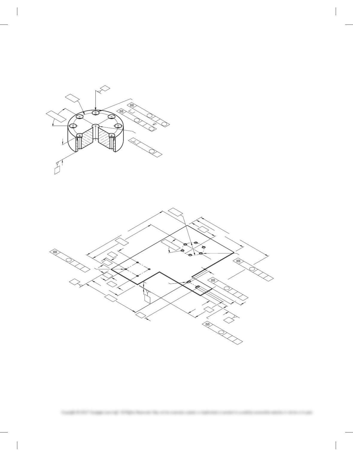
PROBLEM 13.20 (in.)
Part Name: Lock Spacer
Material: SAE 1030
59728_ch13_EOC_ptg01.indd 14 2/3/16 2:21 PM
PROBLEM 13.21 (metric)
Part Name: Mounting Plate
Material: SAE 4140
Ø60 Ø10+0.2
0
8X Ø6.4-6.5
BA
8X Ø9.6-9.8 5.6-6.0
74.0
73.5
8X 45º
B
A
24
±
0.5
Ø0.1 A
M
Ø0.4 AB
M
Ø0.25
M
M
M
PROBLEM 13.22 Geometric tolerancing (metric)
Part Name: Side Panel Mounting Plate
Material: SAE 30308
4X Ø5
4X R
2X 12
40
6X Ø8
6X 60º
2X 6
B
A
25 C
B
M
A
0.5
230
95
75
170
160
260
200
25
40
40
90
80
30
C
C
B
M
A
00.5
C
B
M
A
.5
1.5
Ø60
Ø
C
B
M
A
0.5
Ø
59728_ch13_EOC_ptg01.indd 15 2/3/16 2:21 PM
PROBLEM 13.23 Advanced geometric tolerancing from
actual industry drawing (metric)
Part Name: Pinion Gear Shaft
Material: CRES 15-5PH ASTM A564
Additional General Notes:
1. Finish all over 1.6 µm.
2. Heat treat per Mil-H-6875 to H1100 condition.
3. Penetrant inspect finished part per Mil-Std-271, Group
III. No evidence of linear indications permitted.
4. Part to be clean and free of foreign debris.
Problem based on original art courtesy Aerojet TechSystems Co.
A
A
SECTION A-A
R12.7
Ø51
30º
Ø170
M8 X 1.25-5H
38.10
38.23
Ø
Ø85
6X Ø15
Ø31.75
24.38
+0.05
0
M
Ø0.15
C
Ø0.50
M
C
Ø0.50
BA
M
0.2
E
25.413
25.400
Ø31.750
22.726
Ø
0.05
AC
0.127
C-E
C-E
0.076
D
M
B
0.05
A
R75
Ø36.5
R10
65
B
D
E
C
6X 60º
16
32
235
49
A
32
123
56
47.6
Ø135
4.75
4.77
35.46
35.56
1.5
97
38
18º
Ø9
Ø0.80
M
ABD
15º
59728_ch13_EOC_ptg01.indd 16 2/3/16 2:21 PM
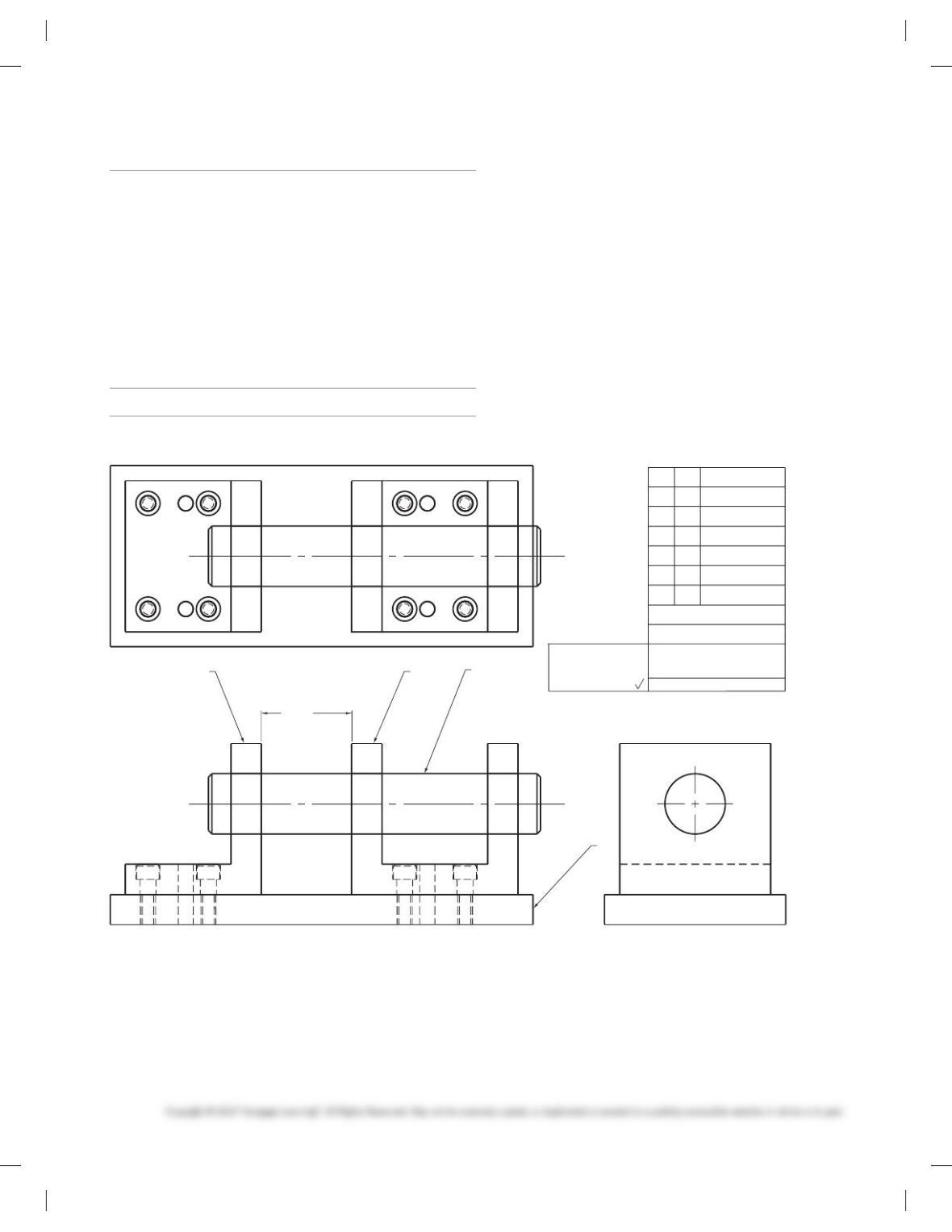
DESIGN PROBLEM
Part 3: Problem 13.24
PROBLEM 13.24 Problem courtesy of Martin Soll.
XYZ CO.
MATERIAL LIST
PART NO.
TITLE
15982-A
TRUNNION ASSEMBLY
TOLERANCES
UNLESS NOTED
±
.1
±
.01
.XXX
.XXX
.XXX
±
.001
MACHINED SURFACES
125
ITEM
DESCRIPTION
1
2
3
QTY
3.000 +.020
-.000
4
1
1
1
1
PLATE
ANGLE
YOKE
PIN
1
234
INSTRUCTIONS
Given the engineering layout below, design and detail the plate,
angle, and yoke per ASME Y14.5-2009 standards. Use arrowless
dimensioning unless otherwise specifi ed by your instructor. Use
the following information and specifi cations:
■ Not all features are shown in all views.
■ Some features that are hidden from view are not drawn with
hidden lines.
■ Item 4 (Pin) is a purchase part. Do not detail this part.
■ Pin specifi cations: [2.00006.0001
Straightness within .0002 over full length.
Clearance fi t in Angle 5 .005/.007
Clearance fi t in Yoke 5 .003/.005
■ Dowell pin specifi cations: [.50006.0005
Interference fi t in Plate 5 .001/.003
Clearance fi t in Angle and Yoke 5 .002/.005
■ Be sure the pin will slide smoothly through the three holes,
■ and the 3.000.020/ .000 spacing is maintained.
59728_ch13_EOC_ptg01.indd 17 2/3/16 2:21 PM

MATH PROBLEMS
Part 4: Problems 13.25 Through 13.34
Round to the nearest tenth.
PROBLEM 13.25 4.849
PROBLEM 13.26 3.650
PROBLEM 13.27 .275
PROBLEM 13.28 5.249
Round to the nearest hundredth.
PROBLEM 13.29 4.849
PROBLEM 13.30 7.0574
PROBLEM 13.31 .27499
Perform the following calculations, rounding appropriately.
PROBLEM 13.32 3.7 1 4.19 1 8.00004
PROBLEM 13.33 7.8 3 6.3 3 5.29
PROBLEM 13.34 Find C using the formula C 5 pD for
D 5 6542 cm.
59728_ch13_EOC_ptg01.indd 18 2/3/16 2:21 PM
174
Chapter 13
Geometric Dimensioning and Tolerancing
Solutions to End-of-Chapter Problems
Part 1: Problems 13.1 Through 13.15
PROBLEM 13.2 Test pump lock nut (metric)
175
PROBLEM 13.5 Half coupling (in.)
176
PROBLEM 13.7 Nut (in.)