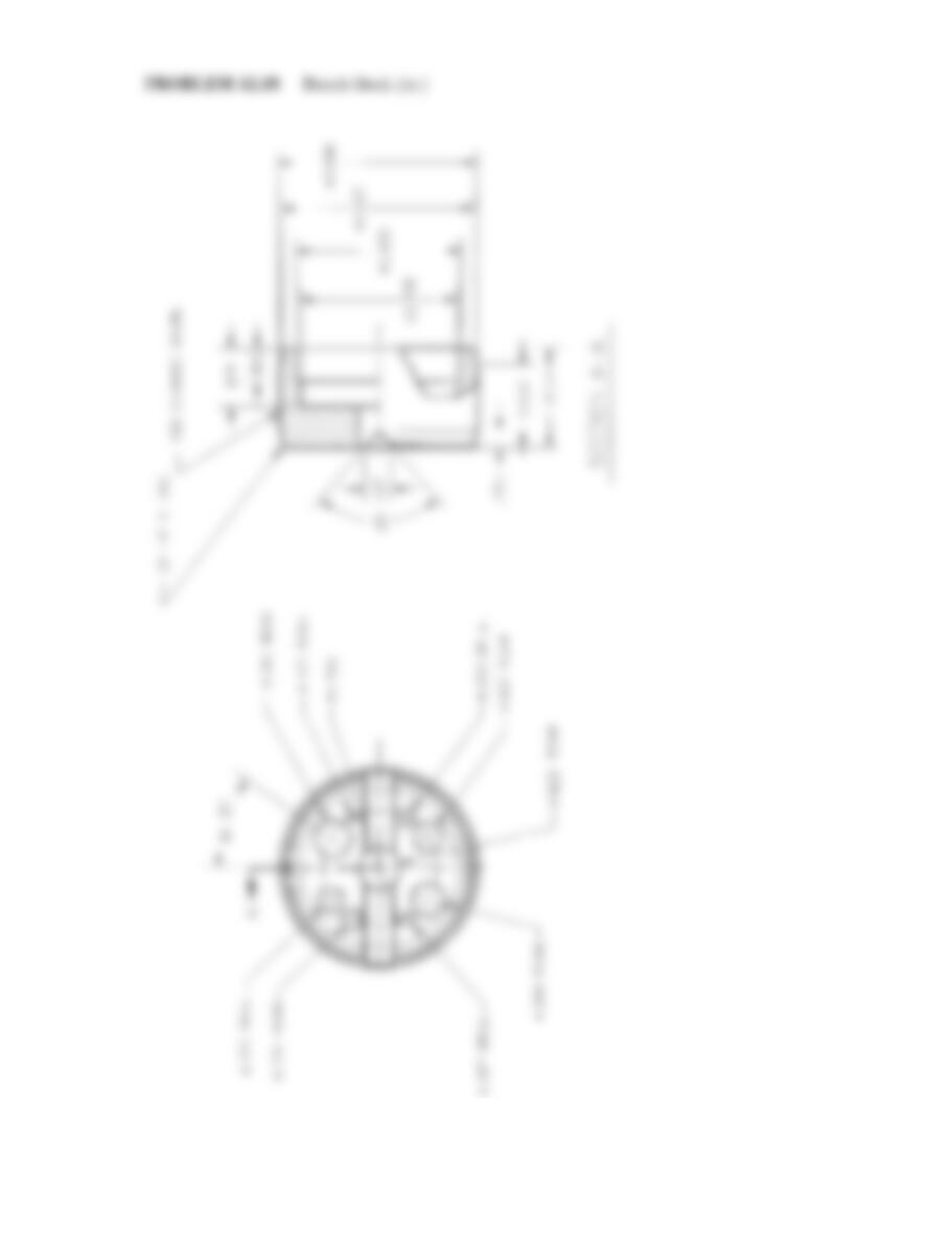
PROBLEM 12.46 Advanced full section, auxiliary section,
and view enlargement from actual industry drawing (in.)
Part Name: Bulk Head
Material: Cast iron
Courtesy Stanley Hydraulic Tools, a Division of the Stanley Works
NOTE: Use dimensioning symbols based on the ASME
Y14.5-2009 standards described in Chapter 10 Dimen-
sioning and Tolerancing. This problem drawing is
based on an outdated standard using abbrevia-
tions and words that should be converted to
symbols as shown in Chapter 10.
30°
15°
12°
.425
.551
.030
.093
.721
R.750
.800
1.656
.938
B
B
A
A
.185
.625
.780
.625
.438
1.065
.290
.250
(.875)
.375
.094
.188
.250
2.200
9.70
.906 .906
#25 DRILL THRU
10–24UNC-2B
THRU
3 HOLES*
#9 DRILL THRU
Ø.328 SF,
.188 DEEP*
#9 DRILL
THRU 3
PLACES*
#47 DRILL
THRU*
Ø1.000
TO DEPTH
SHOWN
Ø.198, .430 DEEP
Ø.875 SF,
.050 DEEP*
1.250
R.688
.625
1.250
3.049
1.244
.690
.0735
.9450
.9445
.907
.905
1.084
1.080
Ø
.5938
.5934
.160
.150
Ø
Ø .940
.970
.960
.402
.399
.722
.720
1.414
1.410
1.084
1.080
Ø
2.437
2.435
Ø
Ø.328
Ø1.250
R.250
R2.750 R1.312
DRILL TO
DEPTH
SHOWN
32
1.768
3
4
DETAIL C
SCALE: 10 X
SECTION A-A
SECTION B-B
SEE DETAIL C
* Convert to proper
ASME standards
59728_ch12_EOC_ptg01.indd 22 03/02/16 10:28 am
NOTE: Use dimensioning symbols based on the ASME
Y14.5-2009 standards described in Chapter 10 Dimen-
sioning and Tolerancing. This problem drawing is
based on an outdated standard using abbrevia-
tions and words that should be converted to
symbols as shown in Chapter 10.
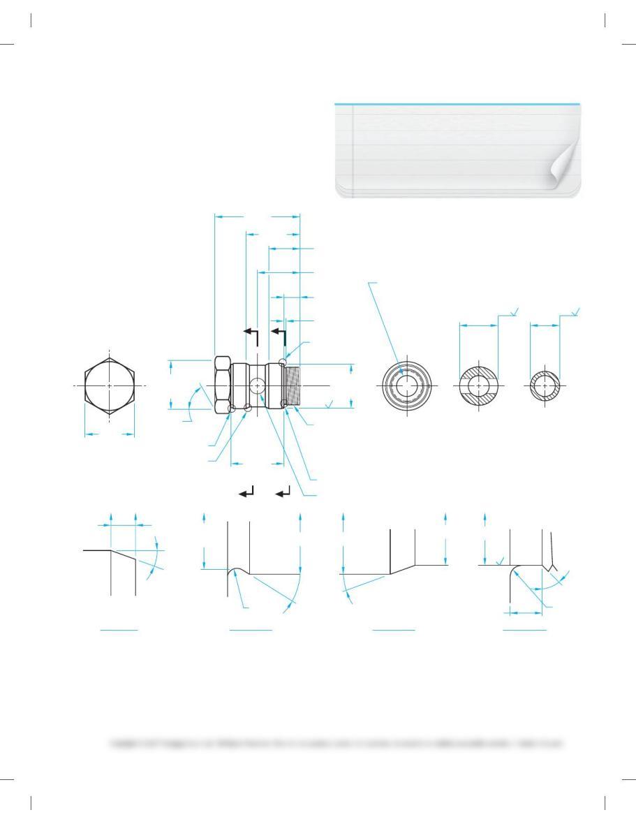
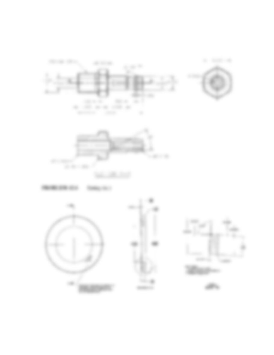
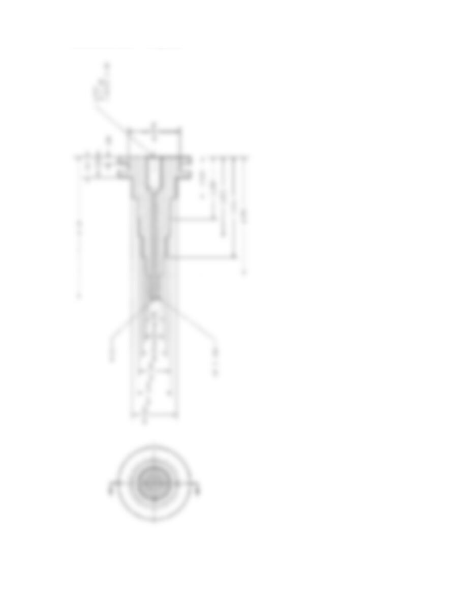
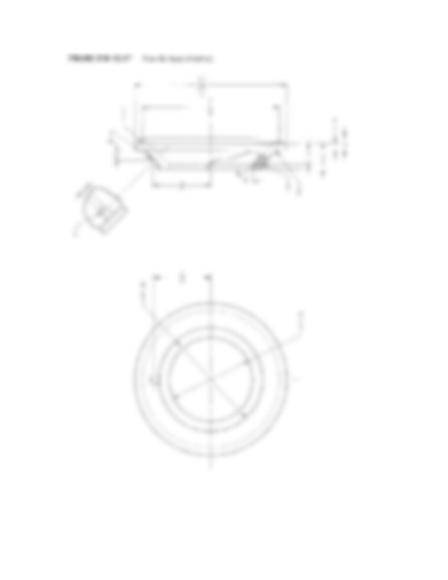
PROBLEM 12.47 Advanced removed sections and view en-
largements from actual industry drawing (in.)
Part Name: Swivel Stem
Material: SAE 4340
Courtesy Stanley Hydraulic Tools, a Division of the Stanley Works.
SECTION B-BSECTION A-A
SEE DETAIL F
SEE DETAIL C
SEE DETAIL D
DETAIL C
SCALE: 10:1
DETAIL F
SCALE: 4X
DETAIL D
SCALE: 10:1
DETAIL E
SCALE: 10:1
SEE DETAIL E
MAJOR
PITCH
15/16 UN-2A
1.3108
1.2994
1.2567
1.2509
1. 19 7
1. 19 2
Ø63
63
1.475
1.465
13/16 DRILL, 2.000 DEEP
Ø63
63
1.562
1.560
2.015
2.025
3.250
2.020
2.040 1. 19 0
1. 17 0
1.600
1.610
.590
.600
.125
.140
Ø
.026
.036
R.015
.030
R
Ø1.875
1.875
HEX STK
.110
.125
608
X
328
158
208458
A
AB
B9/16 DRILL THRU
1.490
1.480
Ø(Ø 1.561) (Ø 1.561)
(Ø 1.470) (Ø 1.195)
(.1325)
59728_ch12_EOC_ptg01.indd 23 03/02/16 10:28 am
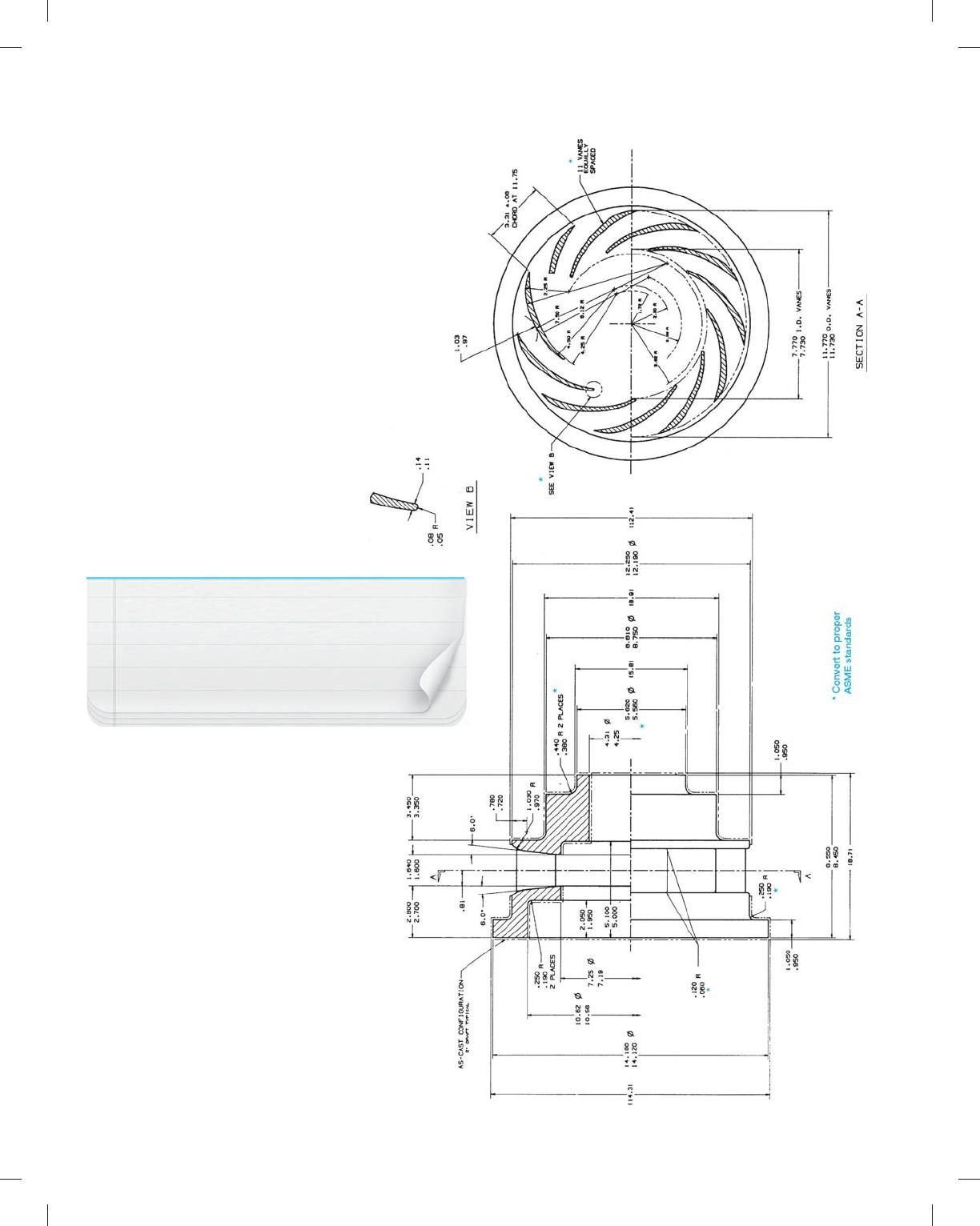
PROBLEM 12.48 Advanced half and full sections
from actual industry drawing (in.)
Part Name: Diffuser Casting
Material: Titanium
SPECIFIC INSTRUCTIONS:
Convert all dimensions to ASME Y14.5-2009 standards as
shown and discussed in this text. Display the casting
material using phantom lines as shown in the engineer’s
layout. Use ANSI standard cutting-plane line.
ALTERNATE INSTRUCTIONS:
Omit phantom line technique for showing casting and
make two drawings: one a casting drawing with only
casting information, and the other a machining drawing
with only machining dimensions and information. Refer
to Chapter 4 for a review of this practice.
NOTE: Use dimensioning symbols based on the ASME
Y14.5-2009 standards described in Chapter 10 Dimen-
sioning and Tolerancing. This problem drawing is
based on an outdated standard using abbrevia-
tions and words that should be converted to
symbols as shown in Chapter 10.
59728_ch12_EOC_ptg01.indd 24 03/02/16 10:28 am
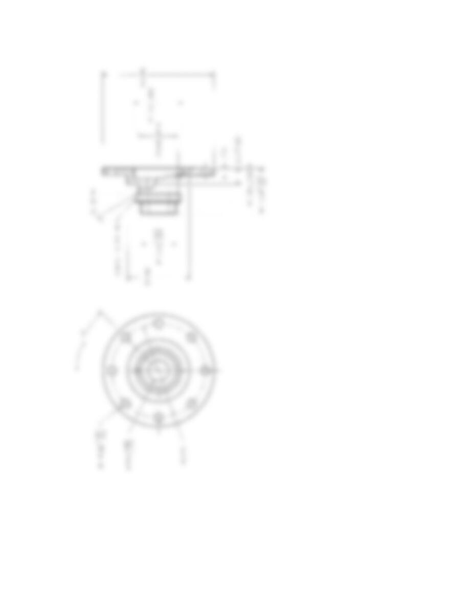
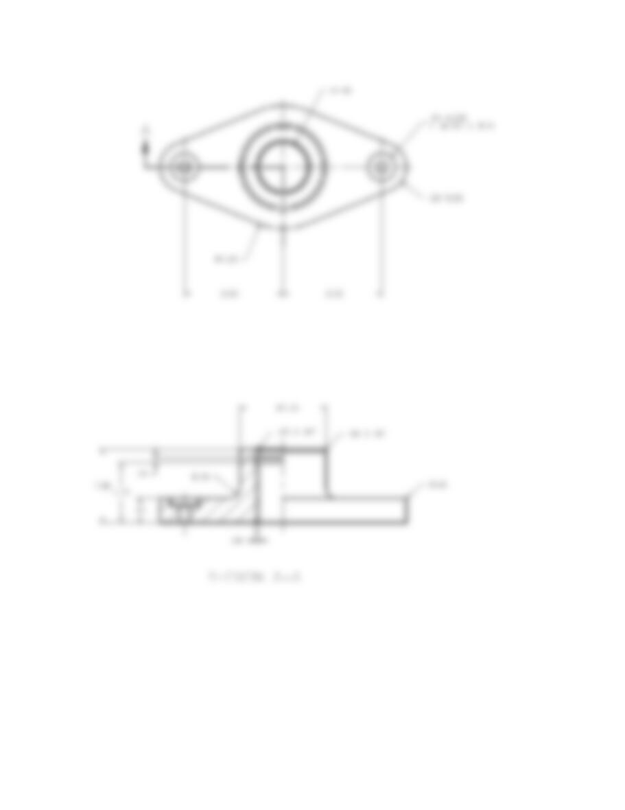
PROBLEM 12.49 Advanced aligned section from actual in-
dustry drawing (in.)
Part Name: Crankshaft Adapter
Material: CI
Courtesy American Hoist and Derrick Company.
728
278
4X M16 X 2-6H
A
A
Ø5.125
Ø6.50
5X Ø.44
5X Ø.75
Ø7.88
Ø
Ø4.12
2.501
2.500
Ø6.25
Ø4.058
4.060
Ø3.25
R.12
R.03
3.04
1.50
.62
.25
2X R.38
125
R.25
4.22
3.47
.44
.62
DETAIL A
.484
2X .504 80
2X 458 X .125
SECTION A-A
A
2X 388
Ø7.50
59728_ch12_EOC_ptg01.indd 25 03/02/16 10:28 am
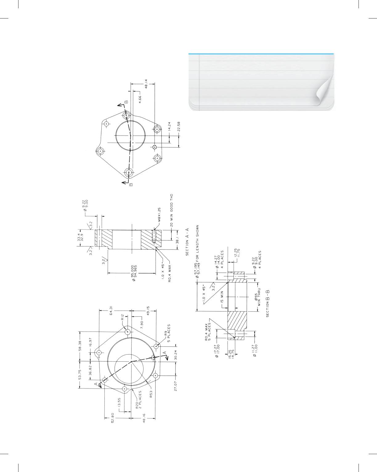
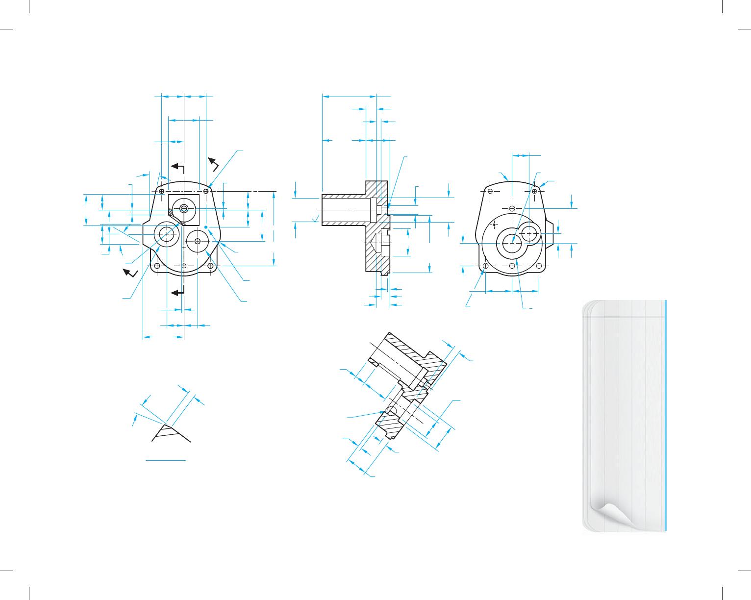
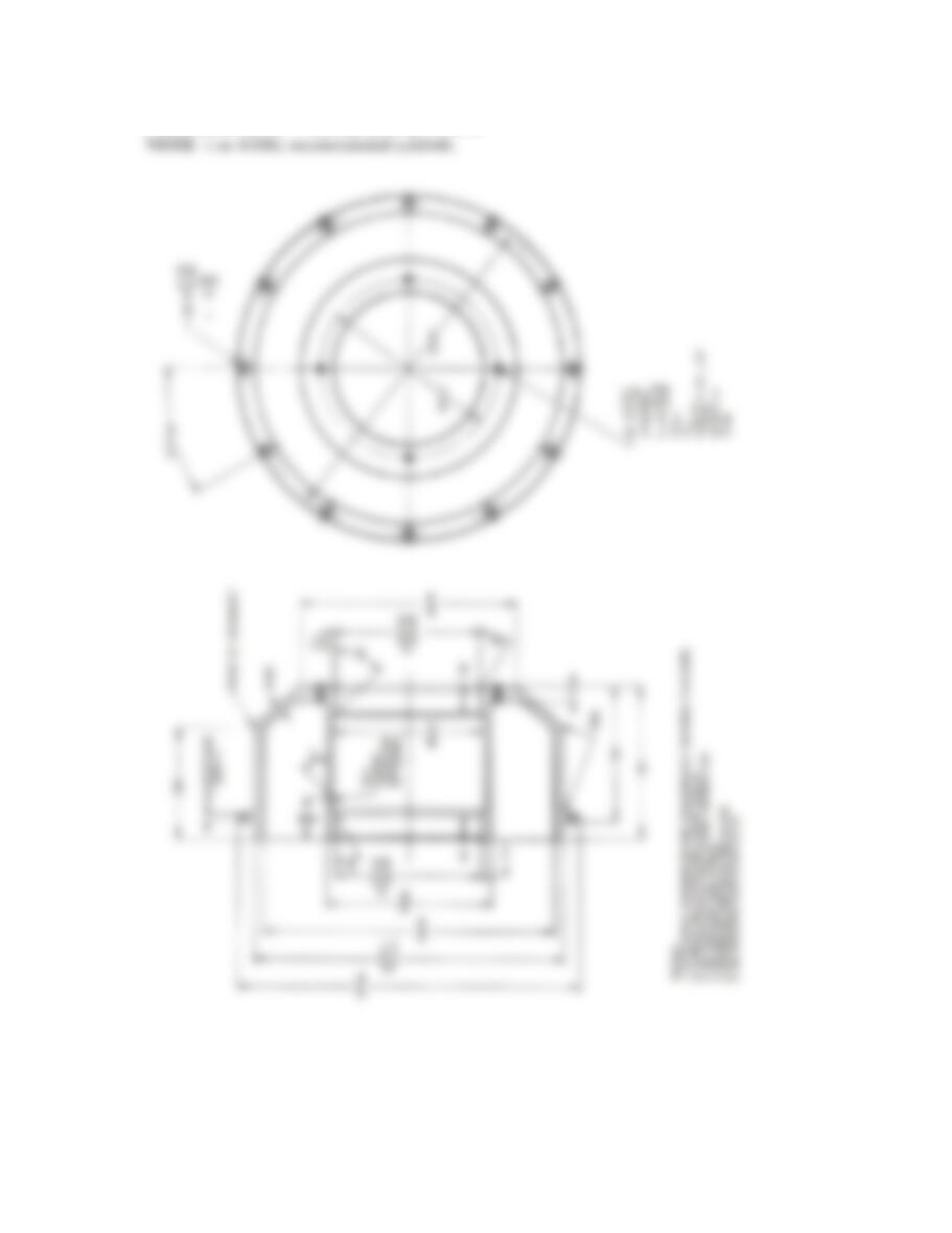
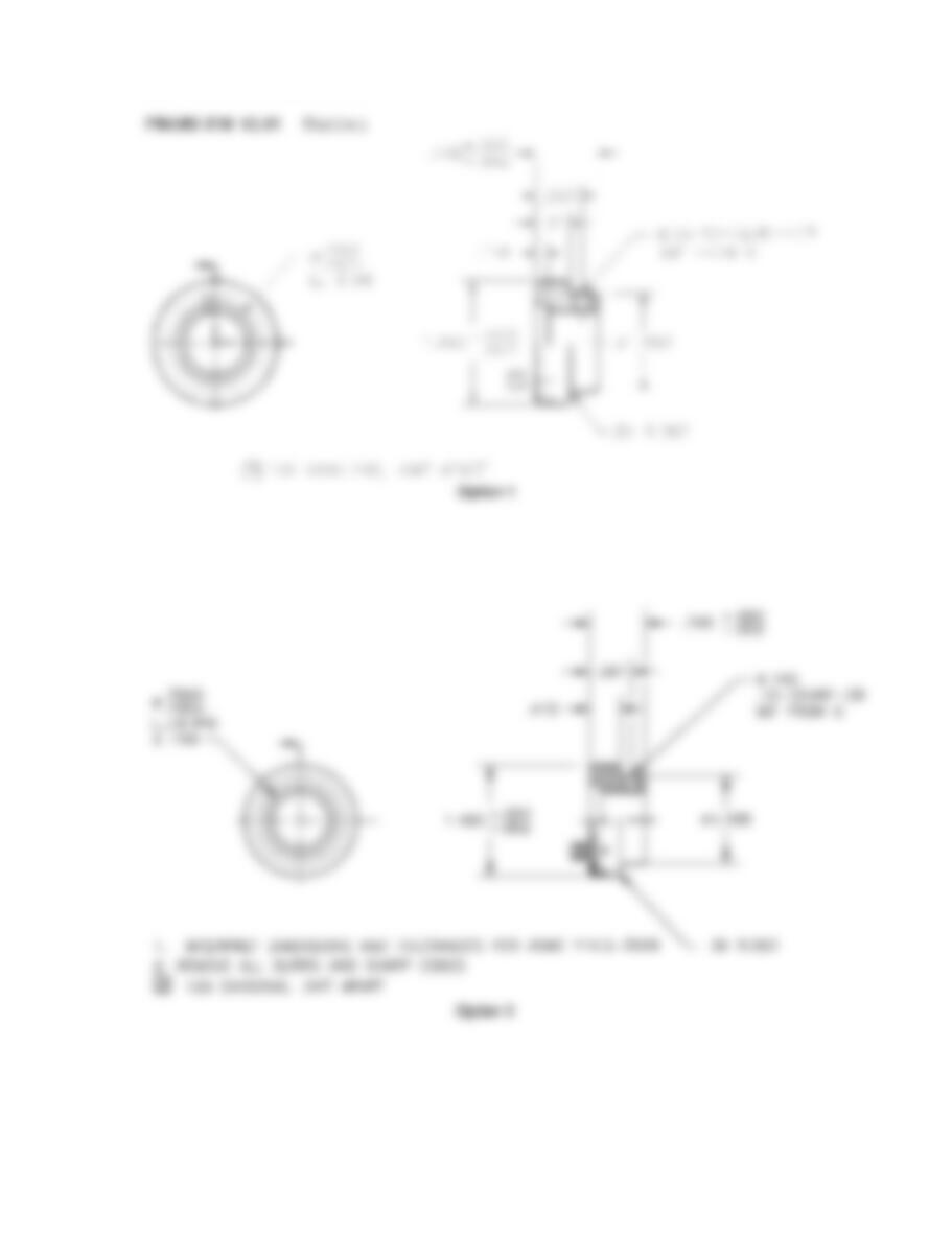
PROBLEM 12.50 Advanced aligned sections from actual
industry drawing (metric)
Part Name: Steering Pump Adapter
Material: HC-80
Courtesy Hyster Company.
NOTE: Use dimensioning symbols based on the ASME
Y14.5-2009 standards described in Chapter 10 Dimen-
sioning and Tolerancing. This problem drawing is
based on an outdated standard using abbrevia-
tions and words that should be converted to
symbols as shown in Chapter 10.
* Convert to proper
ASME standards
*
*
*
59728_ch12_EOC_ptg01.indd 26 03/02/16 10:28 am
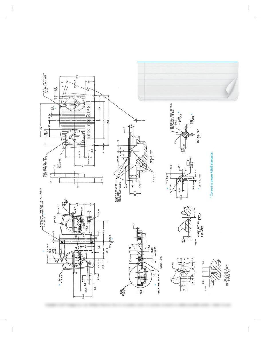
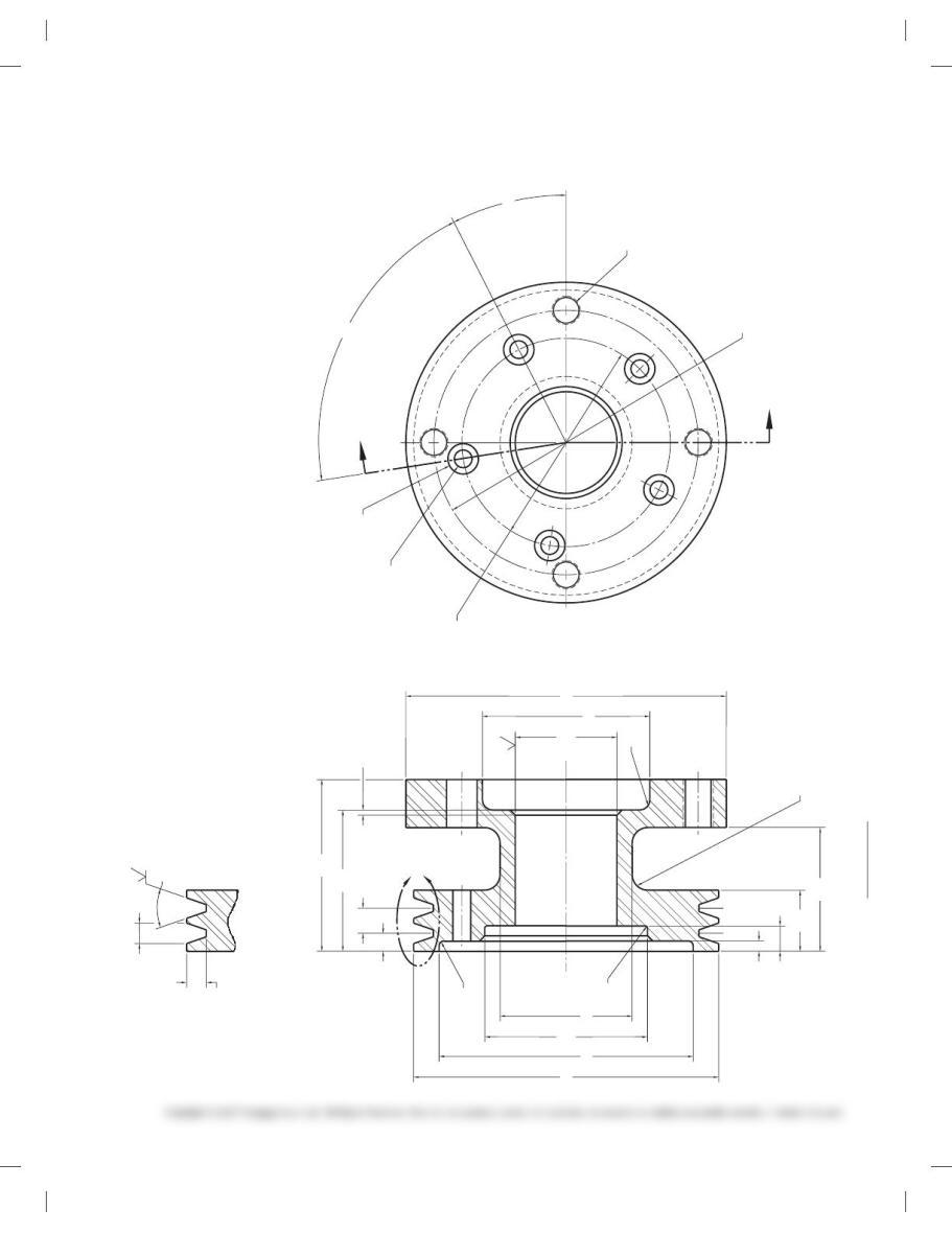
PROBLEM 12.51 Advanced offset section, enlarged views,
from actual industry drawing (metric)
Part Name: Pad-Monotrol
Material: Hi-mount Pro-fax 8623
NOTE: Use dimensioning symbols based on the ASME
Y14.5-2009 standards described in Chapter 10 Dimen-
sioning and Tolerancing. This problem drawing is
based on an outdated standard using abbrevia-
tions and words that should be converted to
symbols as shown in Chapter 10.
SPECIFIC INSTRUCTIONS:
Avoid leaders crossing dimension lines.
Courtesy Hyster Company.
59728_ch12_EOC_ptg01.indd 27 03/02/16 10:28 am
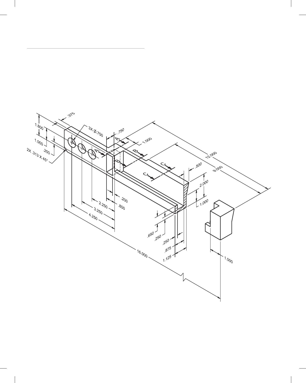
Part 8: Problems 12.52 and12.53
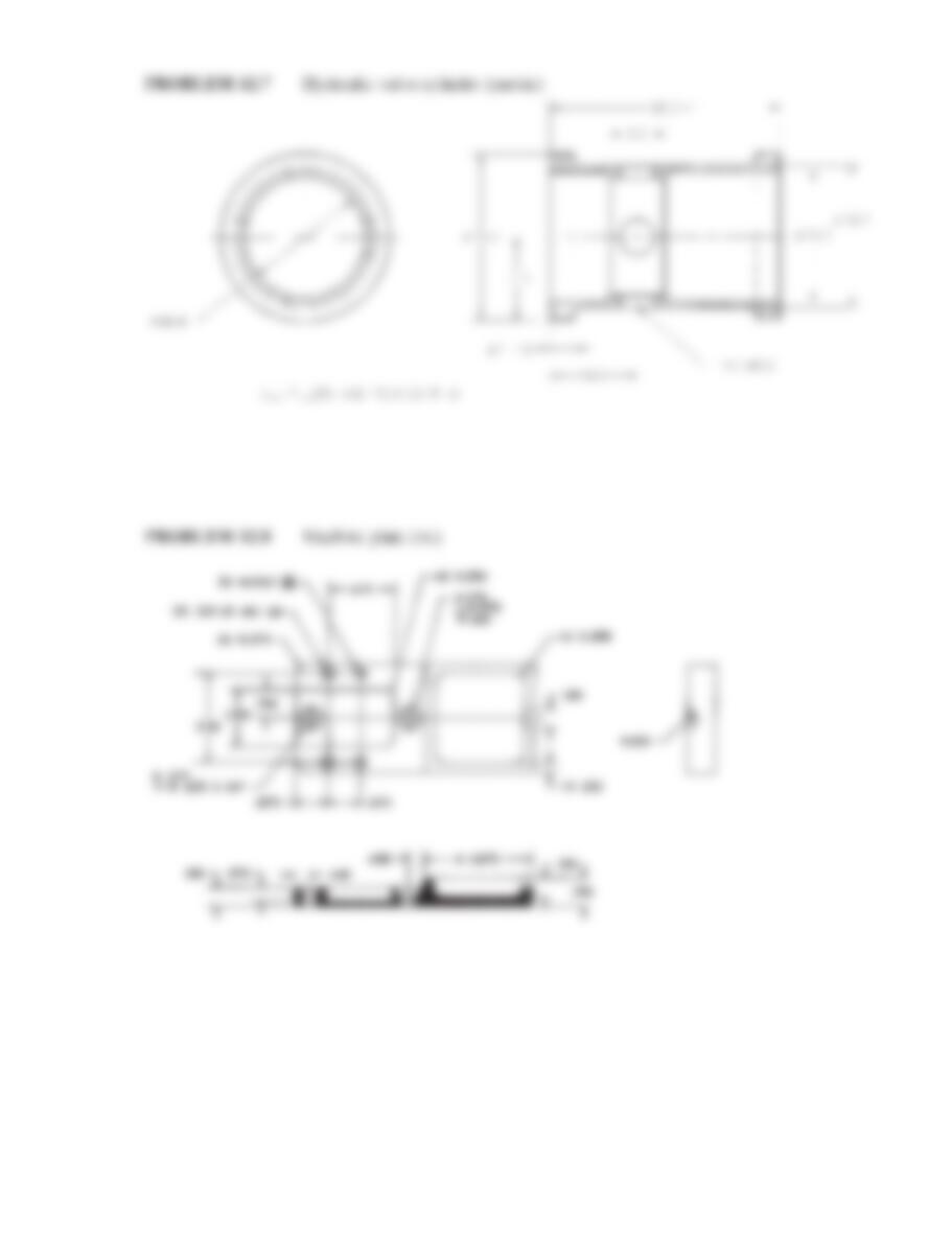
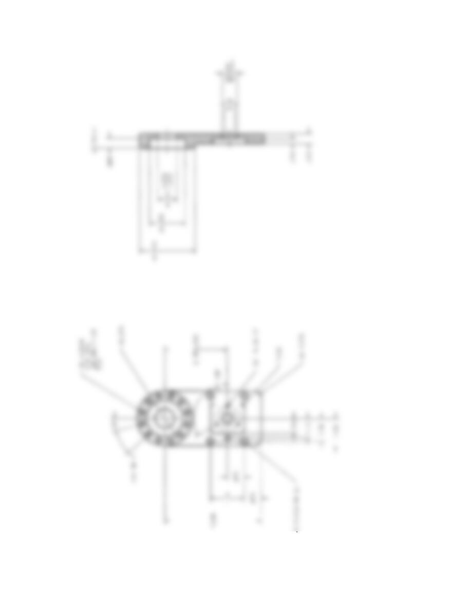
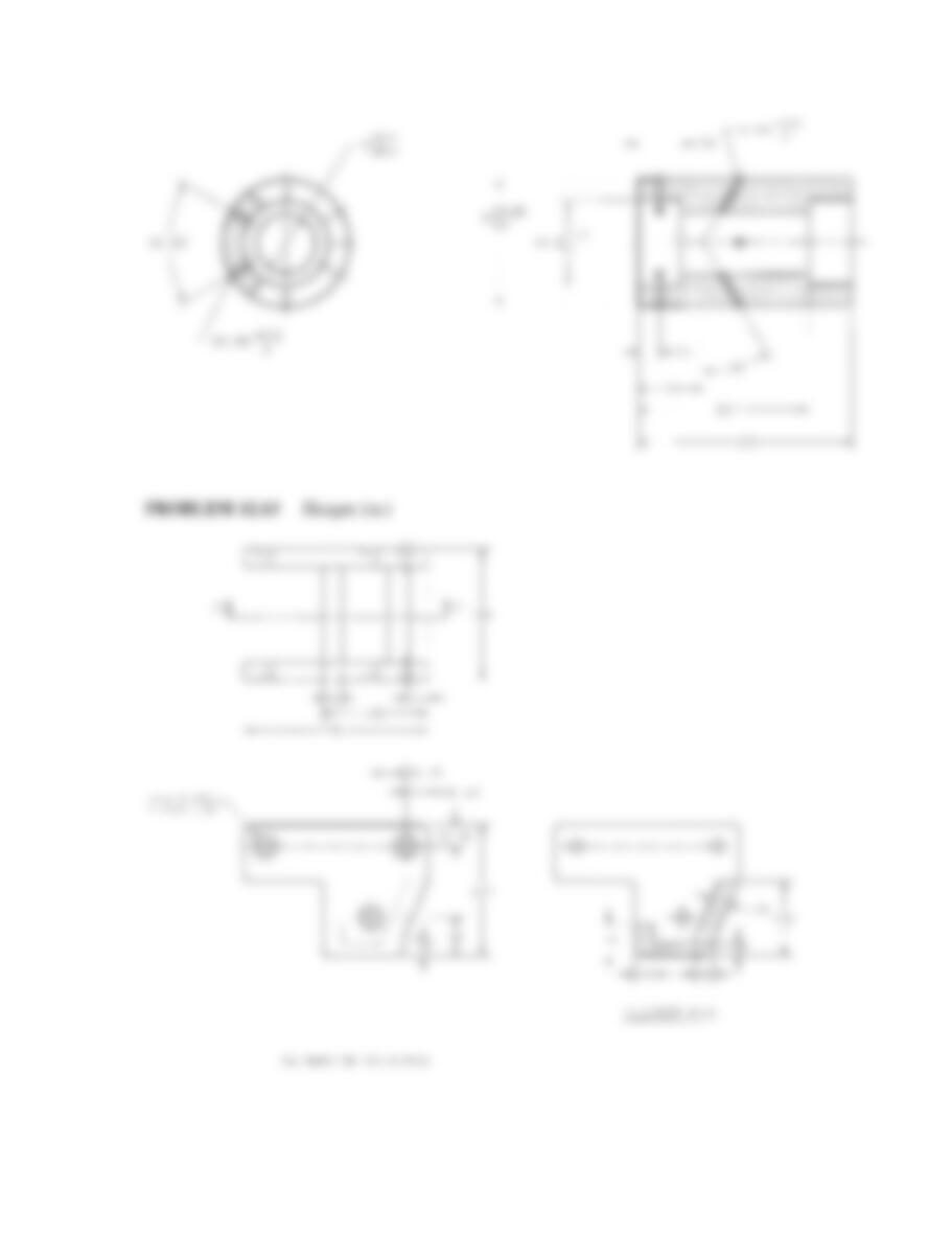
PROBLEM 12.52 Removed sections (in.)
Part Name: Extension Bar
Material: SAE 4320
SPECIFIC INSTRUCTIONS: This part requires at least three re-
moved sections. A front and top view is recommended, and the
recommended section locations are identified. Use conventional
removed section cutting planes and place the removed sections
in alphabetical order from left to right.
PROBLEM 12.53 Removed sections arrow method (in.)
Part Name: Extension Bar
Material: SAE 4320
SPECIFIC INSTRUCTIONS: Use the same drawing found in Prob-
lem 12.52. Use the removed section arrow method for solving this
problem.
59728_ch12_EOC_ptg01.indd 28 03/02/16 10:28 am
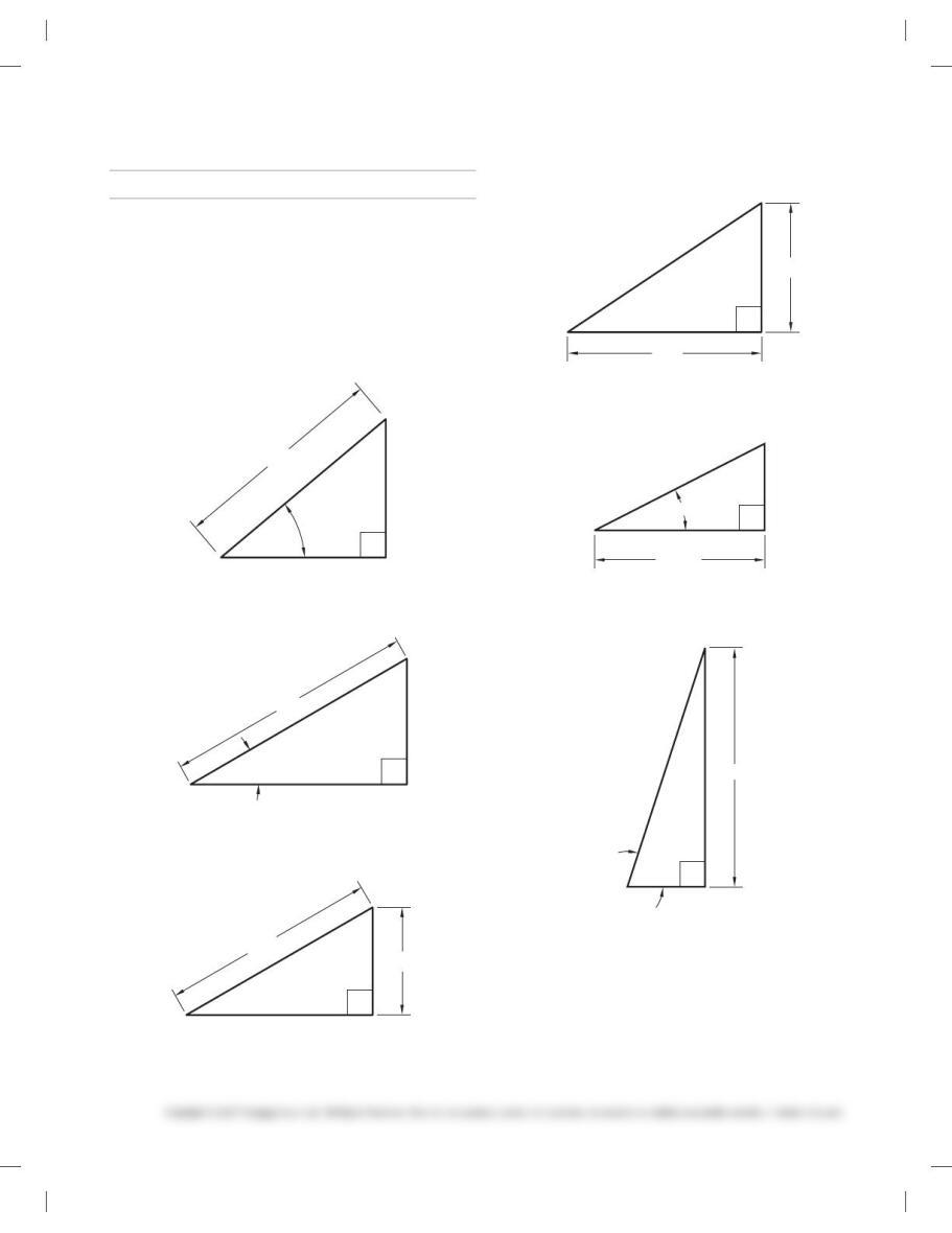
MATH PROBLEMS
Part 9: Problems 12.54 Through12.61
PROBLEM 12.54 A bolt circle with radius 14 in. has six
equally spaced holes. Find the center-to-center distance be-
tween the adjacent holes.
PROBLEM 12.55 A bolt circle with radius 16 in. has eight
equally spaced holes. Find the center-to-center distance be-
tween the adjacent holes.
PROBLEM 12.56 Find side y of the right triangle shown
below.
1′-8″
y
40°
PROBLEM 12.57 Find side x of the right triangle shown be-
low. (Hint: Use cosine.)
x
30°
5′-2″
PROBLEM 12.58 Find angle A of the right triangle shown
below.
1′-8″
3′-4″
A
PROBLEM 12.59 Find angle [ of the right triangle shown
below.
1′-5″
1′-0″
∅
PROBLEM 12.60 Find side y of the right triangle shown
below.
712mm
y
278
PROBLEM 12.61 Find side r of the right triangle shown
below.
728
100cm
r
59728_ch12_EOC_ptg01.indd 29 03/02/16 10:28 am
133
Chapter 12
Sections, Revolutions, and Conventional Breaks
Solutions to End-of-Chapter Problems
Part 1: Problems 12.1 Through 12.4
134
(Note: Problem solutions are provided without border and sheet blocks, which should be
included in student drawings.)
Part 2: Problems 12.5 Through 12.13
PROBLEM 12.5 Fitting (in.)
135
136
PROBLEM 12.9 Face plate (in.)
137
PROBLEM 12.10 Plug (in.)
138
PROBLEM 12.11 Hub (in.)
139
PROBLEM 12.12 Hydraulic valve cylinder (metric)
140
Part 3: Problem 12.14
PROBLEM 12.14 Bearing housing (metric)
141
Part 4: Problems 12.15 and 12.16
142
PROBLEM 12.16 Rod support (in.)
143
Part 5: Problems 12.17 Through 12.19
144