
CHAPTER 12 SECTIONS,
REVOLUTIONS, AND
CONVENTIONAL BREAKS PROBLEMS
INSTRUCTIONS
The following problems give you a finished view with a proposed
cutting-plane line. Complete the cutting-plane line and the other
view by drawing the section that properly correlates with the
finished view and given cutting-plane line. A small pictorial view
is given to assist you in visualization. Do not draw the pictorial
view. Measure the given views and transfer the measurements to
your drawing. You can also make a print of the problem or prob-
lems page and sketch or draw the completed views on the copy.
Confirm the preferred method with your instructor.
To access CADD template files with predefined drafting
settings, go to the Student Companion Website, select
Student Downloads, Drafting Templates, and then select
the appropriate template file. Use the templates to create new
designs, as a resource for drawing and model content, or for
inspiration when developing your own templates. The ASME-
Inch and ASME-Metric drafting templates follow ASME, ISO,
and related mechanical drafting standards. Drawing templates
include standard sheet sizes and formats and a variety of
appropriate drawing settings and content. You can also use a
utility such as the AutoCAD DesignCenter to add content from
the drawing templates to your own drawings and templates.
Consult with your instructor to determine which template
drawing and drawing content to use.
DRAFTING TEMPLATES
59728_ch12_EOC_ptg01.indd 2 03/02/16 10:27 am
FULL SECTION ALIGNED SECTION
HALF SECTION OFFSET SECTION
2X Ø.50
.75
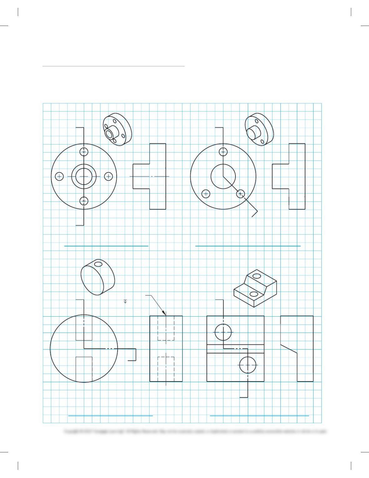
PROBLEM 12.2PROBLEM 12.1
PROBLEM 12.3 PROBLEM 12.4
Part 1: Problems 12.1 Through 12.4
Given objects with recommended multiviews having missing
lines or missing views, draw the multiviews using third-angle
projection. Each square on the given grid represents 1 in.
(25 mm). Use appropriate size ASME standard sheet size and
sheet blocks for each problem unless otherwise specified by
your instructor.
59728_ch12_EOC_ptg01.indd 3 03/02/16 10:27 am
Instructions
1. From the selected engineering sketch or layout, determine
the needed views and sections.
2. Make a sketch of the selected views and sections as close to
correct proportions as possible. Do not spend a lot of time
because the sketch is only a guide. Indicate cutting-plane
lines and dimension placement.
3. Using your sketch as a guide, draw the multiviews and sec-
tional views necessary to describe the part completely. Lay
out the drawing on an adequately sized ASME sheet with
border and sheet blocks. Select a scale that properly details
the part on the selected sheet size. Use unidirectional
dimensioning.
4. Include the following general notes at the lower left corner
of the sheet .5 in. each way from the corner border lines:
1. DIMENSIONS AND TOLERANCES PER ASME
Y14.5-2009.
2. REMOVE ALL BURRS AND SHARP EDGES.
3. UNSPECIFIED TOLERANCES:
Use the following for tolerances for unspecified inch values. A
tolerance block is recommended as described in Chapter 2, and
as shown in problems for Chapter 10, unless otherwise
specified.
For metric drawings, provide a general note that states: Tol-
erances for unspecified dimensions comply with ISO 2768-m.
Provide a general note that states surface finish 3.2 mm unless
otherwise specified.
1. The engineering layouts may not be dimensioned properly.
This is similar to what you can expect in industry. You can-
not assume that what the engineer gives you complies with
the drafting standards described throughout this textbook.
Verify the correct practice before placing dimensions. For
example, the diameter symbol should precede the diameter
dimension, and leaders should not cross over dimension
lines. Check other line and dimensioning techniques for
proper standards. Actual industry drawings are provided as
advanced problems throughout.
NOTE: Additional notes can be required, depend-
ing on the specifications of each individual
assignment.
Unspecified Tolerances
Decimals In.
X6.1
XX 6.01
XXX 6.005
ANGULAR 6309
FINISH 125 µin.
59728_ch12_EOC_ptg01.indd 4 03/02/16 10:27 am
Part 2: Problems 12.5 Through12.13
PROBLEM 12.5 Full section (in.)
Part Name: Fitting
Material: Bronze
Finish All Over: 63 min.
Refer to Chapter 10 Dimensioning and Tolerancing for proper di-
mensioning practices. Engineering sketches may not display cor-
rect practices. This problem can require a front view, a side view
showing the hexagon, and a full section to expose the interior
features for dimensioning.
PROBLEM 12.6 Full section and view enlargement (in.)
Part Name: Spring
Material: SAE 1060
Problem based on original art courtesy Stanley Hydraulic Tools,
Division of The Stanley Works.
Heat-treat:
1. Austenitize at 1475 8F. Inthis type of heat treatment, a steel
is held above a critical temperature long enough for trans-
formation to occur.
2. Direct quench in agitated oil.
3. Temper to RcC 44–46.
59728_ch12_EOC_ptg01.indd 5 03/02/16 10:27 am
PROBLEM 12.7 Full section (metric)
Part Name: Hydraulic Valve Cylinder
Material: Phosphor bronze
All Fillets and Rounds: R.1
PROBLEM 12.8 Full section (in.)
Part Name: Machine Plate
Material: 6160 T6 steel
PROBLEM 12.9 Full section (in.)
Part Name: Face Plate
Material: 6160 T6 steel
59728_ch12_EOC_ptg01.indd 6 03/02/16 10:27 am

PROBLEM 12.10 Full section, dimensioning cylindrical
shapes (in.)
Part Name: Plug
Material: Phosphor bronze
PROBLEM 12.11 Full section or half section (in.)
Part Name: Hub
Material: Cast iron
SPECIFIC INSTRUCTIONS: Convert the broken-out section in
the given drawing to a full section. Type of section used affects
view selection.
PROBLEM 12.12 Full and broken-out section (metric)
Part Name: Hydraulic Valve Cylinder
Material: Phosphor bronze
Proposed sections and section lines are not given in engineer’s
layout. Refer to “The Engineering Design Application” at the be-
ginning of Chapter 12.
PROBLEM 12.13 Full section (in.)
Part Name: Hanger
Material: SAE 1030
Fillets and rounds: R.062
59728_ch12_EOC_ptg01.indd 7 03/02/16 10:27 am
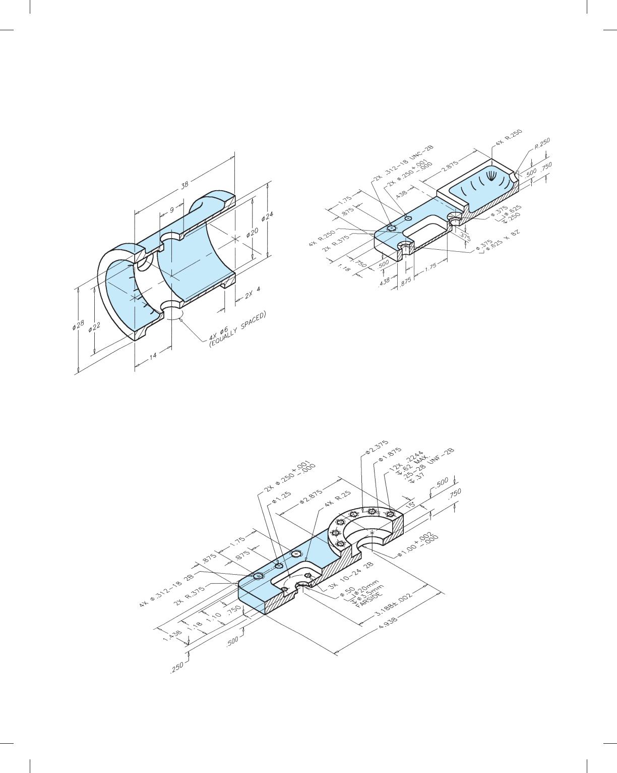
Part 3: Problem 12.14
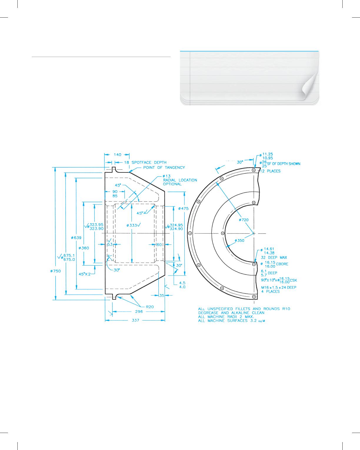
PROBLEM 12.14
Advanced full section from engineer’s
sketch (metric)
Part Name: Bearing Housing
Material: SAE 1015
Courtesy Aerojet TechSystems Co.
NOTE: Use dimensioning symbols based on the ASME
Y14.5-2009 standards described in Chapter 10 Dimen-
sioning and Tolerancing. This problem drawing is
based on an outdated standard using abbrevia-
tions and words that should be converted to
symbols as shown in Chapter 10.
Note the following abbreviations:
CBORE—counterbore
SF—spotface
12 X
59728_ch12_EOC_ptg01.indd 8 03/02/16 10:27 am
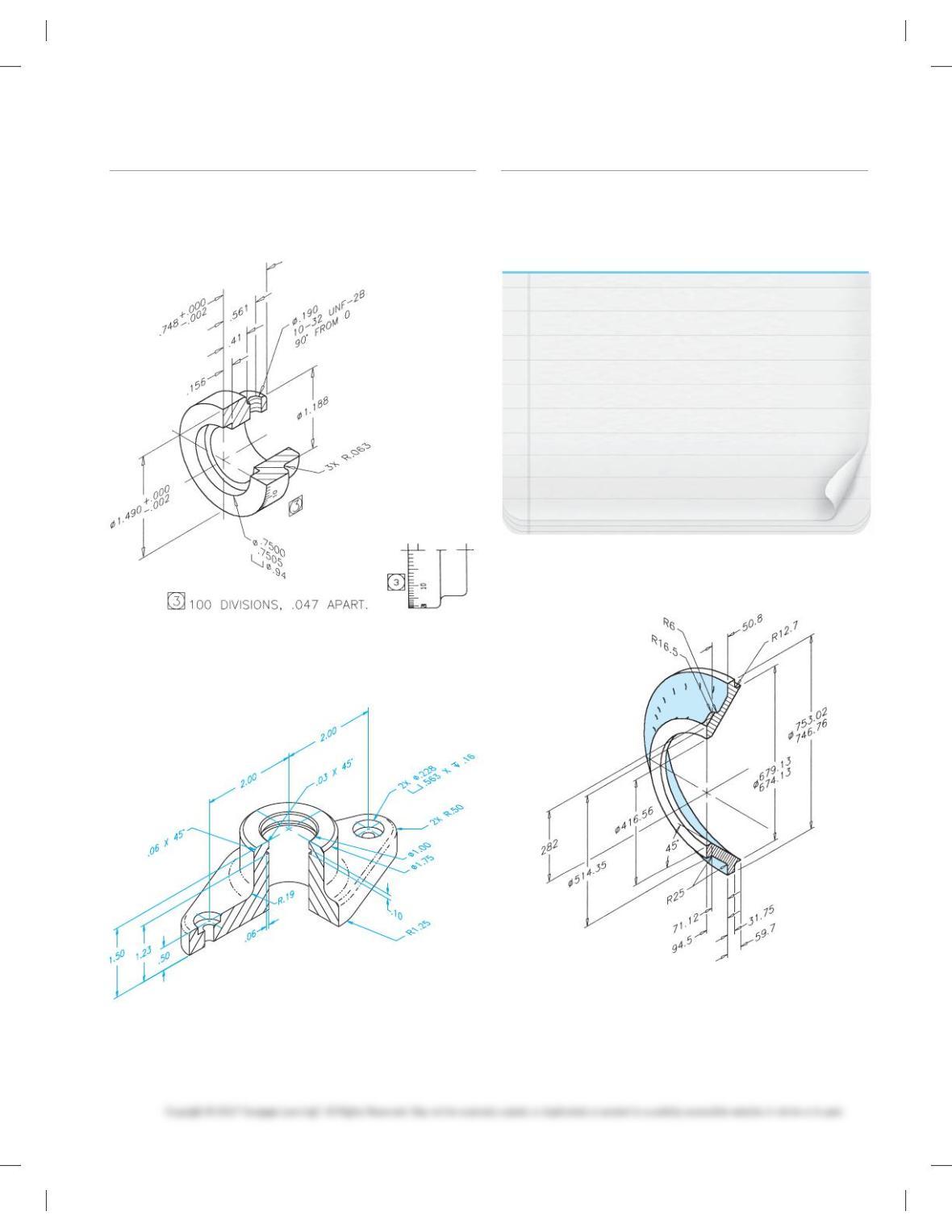
Part 4: Problems 12.15 and12.16
PROBLEM 12.15 Half section (in.)
Part Name: Dial
Material: Bronze
PROBLEM 12.16 Half section (in.)
Part Name: Rod Support
Material: 6061–T6 aluminum
Fillets: R.03 unless otherwise specified.
Part 5: Problems 12.17 Through 12.19
PROBLEM 12.17 Half section and auxiliary view (metric)
Part Name: Nozzle Base
Material: Titanium, ASTM-B367 Grade C3
NOTE: Add the following note to the drawing using
all uppercase text: Clean casting by mechanical blast-
ing prior to alpha case removal. Chemically remove al-
pha case prior to inspection of castings using procedure
approved by procurement activity. Cast surfaces shall
be visually inspected and be free from cracks, tears,
laps, shrinkage, and porosity. Radiographically inspect
castings per MIL-STD-271 acceptance criteria for po-
rosity and inclusions per ASTM-E-446 and for cavity
shrinkage per ASTME- 192 (plates for .75 wall thick–
ness). Severity levels of casting defects shall be no
greater than tabulated here for the indicated
casting areas.
Provide adequate views to avoid crossing extension lines over
dimension lines.
59728_ch12_EOC_ptg01.indd 9 03/02/16 10:27 am
PROBLEM 12.18 Half section and broken-out section (in.)
Part Name: Bench Block
Material: AISI 1018
Case harden: .020 Deep 59-60 Rockwell C scale or AISI 41-40
Oil Quench 40-45 8C
Ream tolerance:1.000
2
2
.0000
PROBLEM 12.19 Half section (metric)
Part Name: Idler Pulley
Material: SAE 4310
Fillets and rounds: R3.2 mm
NOTE: Many diameter dimensions should be
placed on left- and right-side views.
59728_ch12_EOC_ptg01.indd 10 03/02/16 10:27 am
Part 6: Problems 12.21 Through 12.39
PROBLEM 12.21 Offset section (in.)
Part Name: Mounting Plate
Material: AISI 1020
Fillets: R.03 unless otherwise specified.
PROBLEM 12.22 Offset section (in.)
Part Name: Die Casting
Material: SAE 6150
SPECIFIC INSTRUCTIONS: Convert all dimensions to ASME
Y14.5 standards as shown and discussed in this textbook.
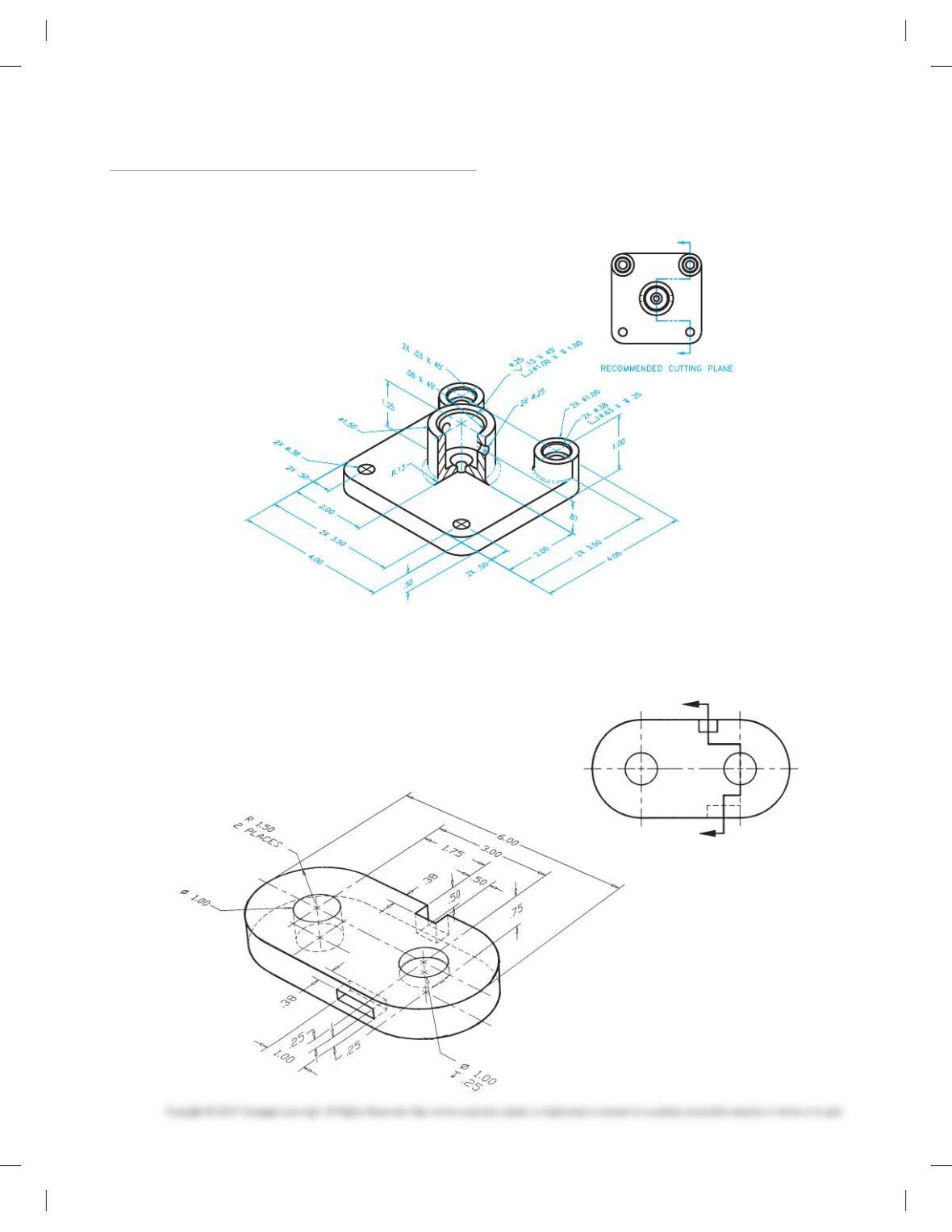
RECOMMENDED CUTTING PLANE
59728_ch12_EOC_ptg01.indd 11 03/02/16 10:27 am
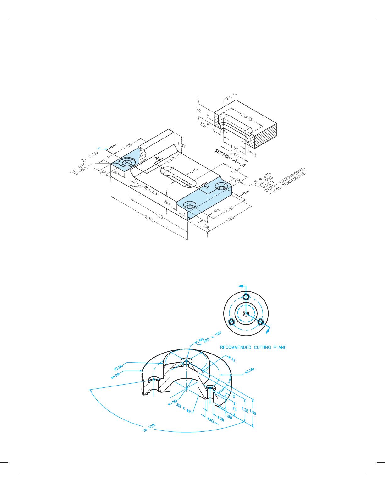
PROBLEM 12.23 Offset section (in.)
Part Name: Drill Plate
Material: SAE 1020
Case harden: 55 Rockwell C scale
Fillets and rounds: R.12
FAO: 63 min.
PROPOSED CUTTING PLANE
PROBLEM 12.24 Aligned section (in.)
Part Name: Shaft Retainer
Material: SAE 4340
Fillets and rounds: R.06 unless otherwise specified.
59728_ch12_EOC_ptg01.indd 12 03/02/16 10:27 am
PROBLEM 12.25 Aligned section (in.)
Part Name: Hub
Material: SAE 3145
Fillets and rounds: R.125
PROBLEM 12.26 Broken-out section (in.)
Part Name: Taper Shaft
Material: SAE 4320
FAO: 16 min.
59728_ch12_EOC_ptg01.indd 13 03/02/16 10:27 am
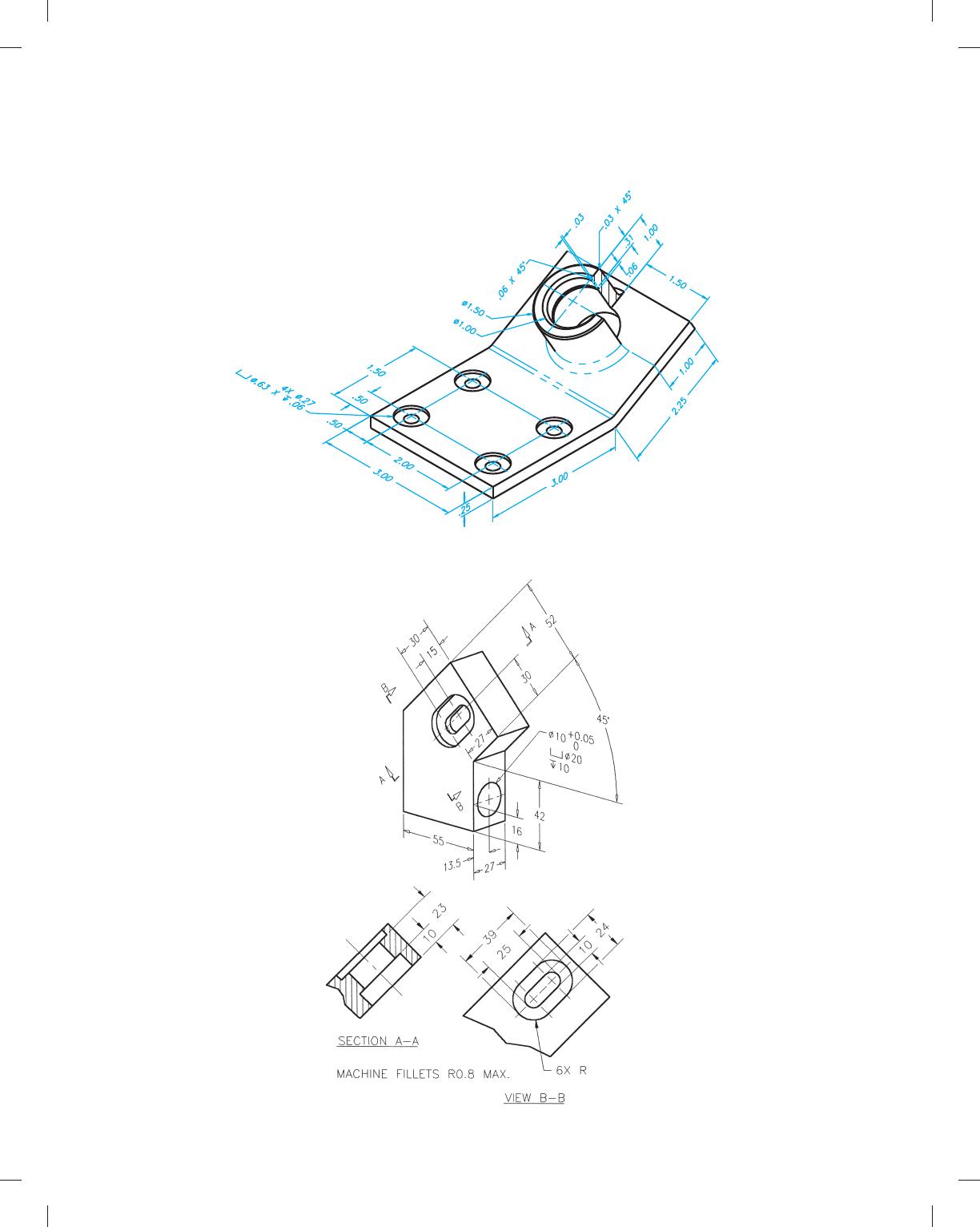
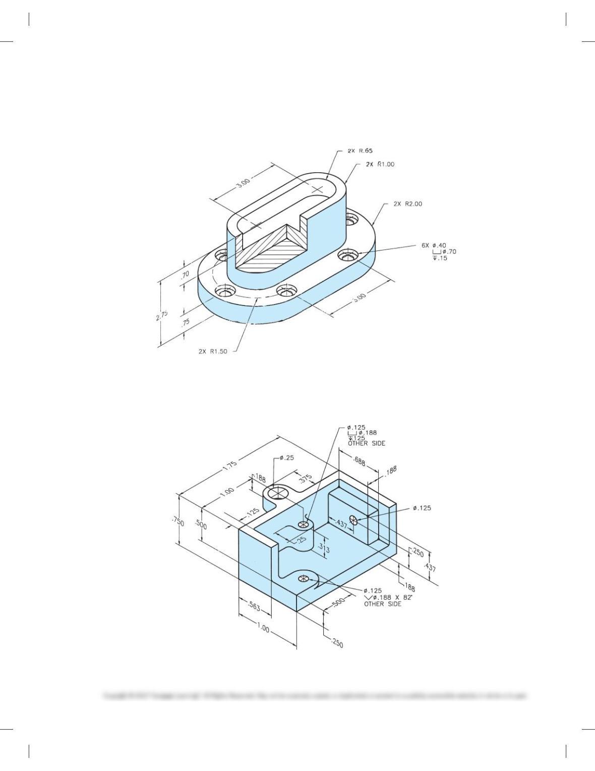
PROBLEM 12.27 Auxiliary section (in.)
Part Name: Angle Bracket
Material: 6061-T6 aluminum
Fillets: R.13 unless otherwise specified.
Rounds: R.38 unless otherwise specified.
PROBLEM 12.28 Auxiliary section (metric)
Part Name: Gear Base
Material: SAE 2340
Finish All Over: 0.8 mm
59728_ch12_EOC_ptg01.indd 14 03/02/16 10:27 am
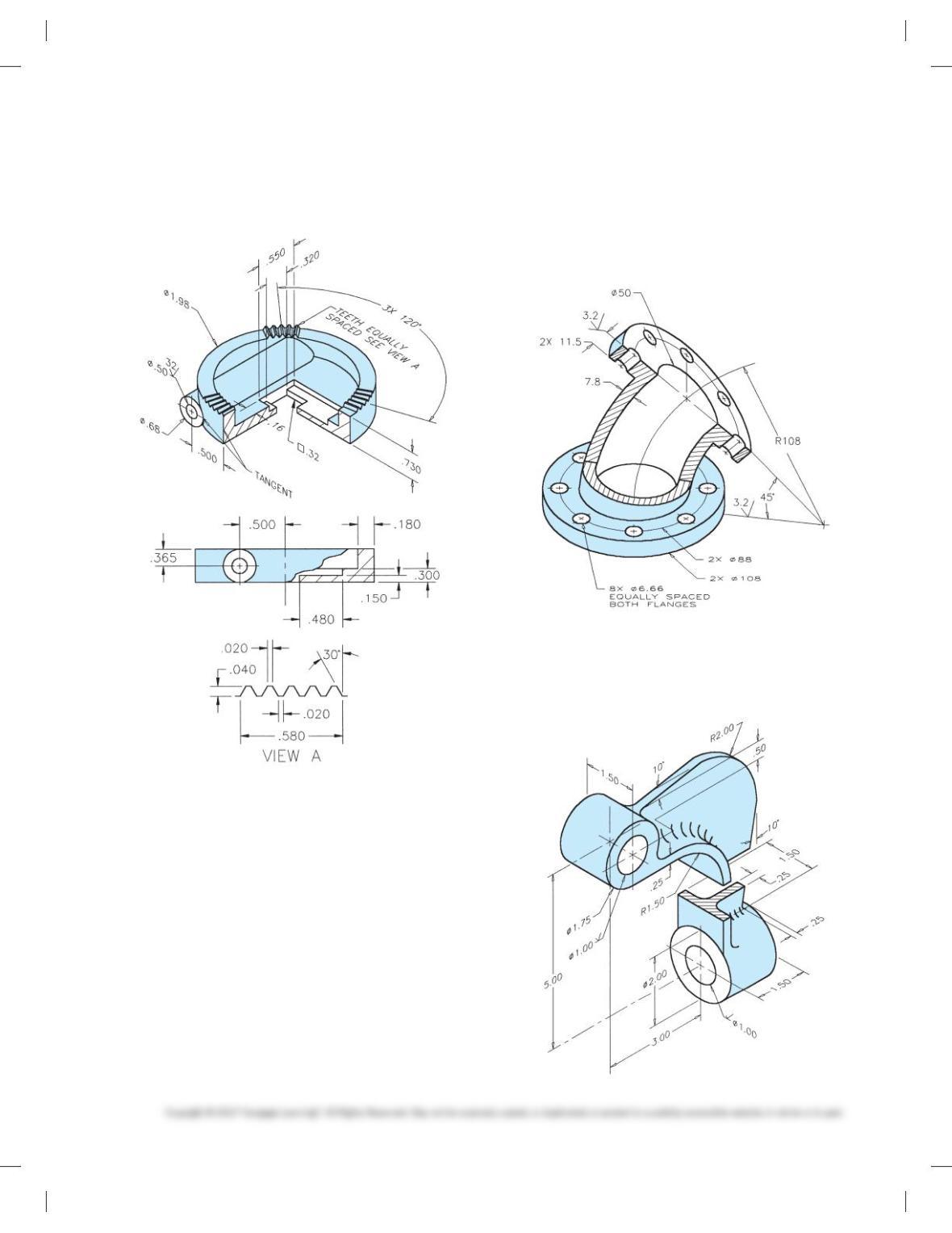
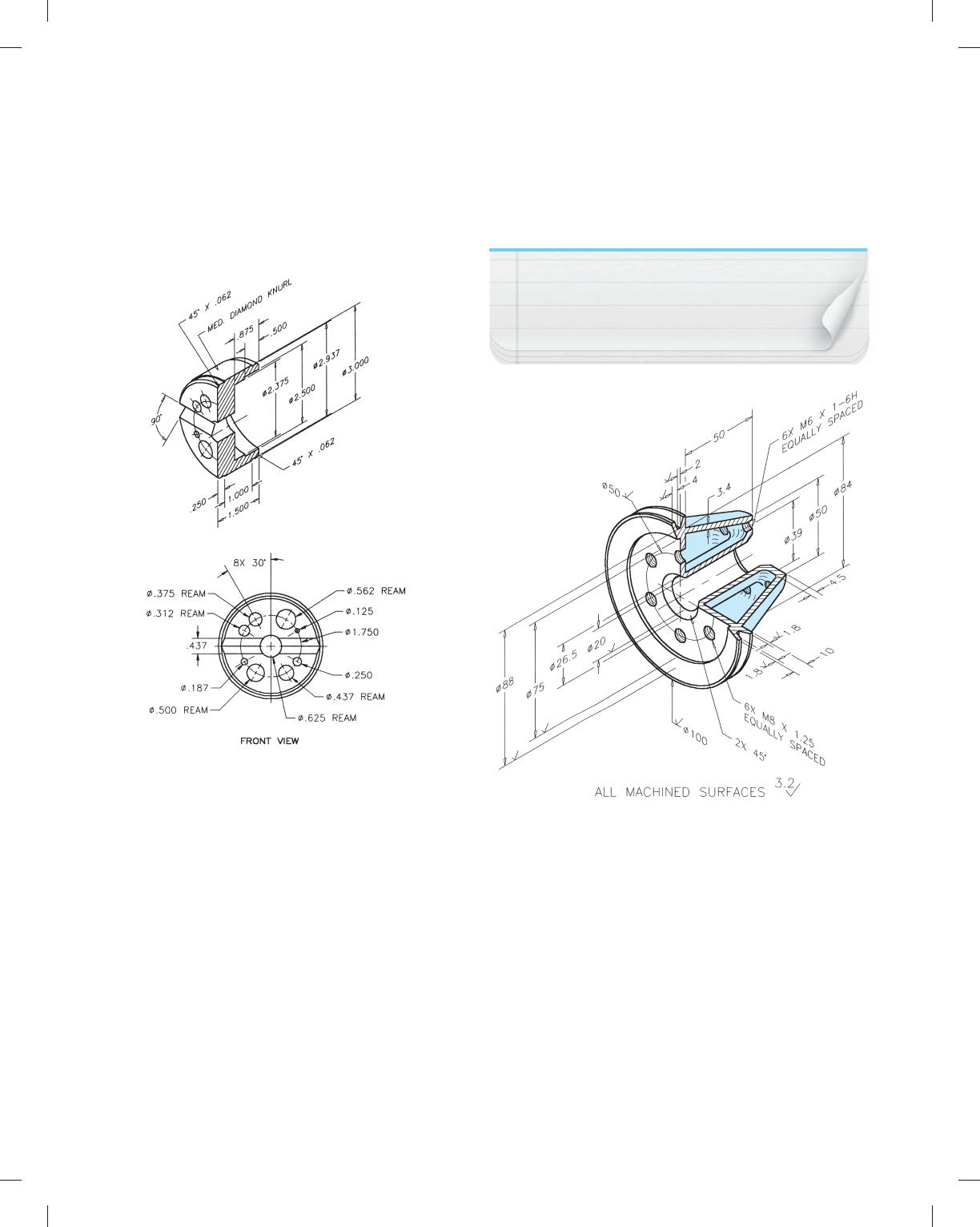
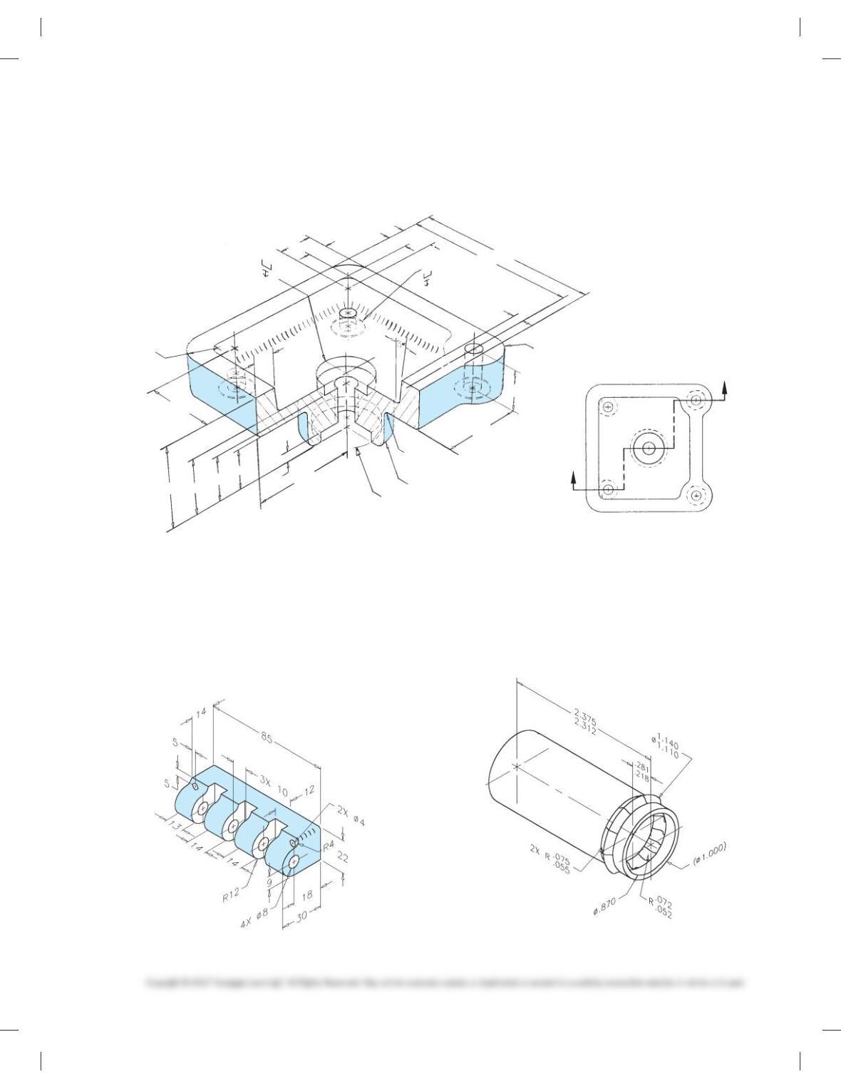
PROBLEM 12.29 Broken-out section, view enlargement (in.)
Part Name: Clamp Cap
Material: Cast aluminum
Fillets and rounds: R.06
PROBLEM 12.30 Broken-out section (metric)
Part Name: 50-mm 458 Elbow
Material: Cast iron
Fillets and rounds: R4mm
SPECIFIC INSTRUCTIONS: Consider bottom view or auxiliary
view for hole pattern dimensions.
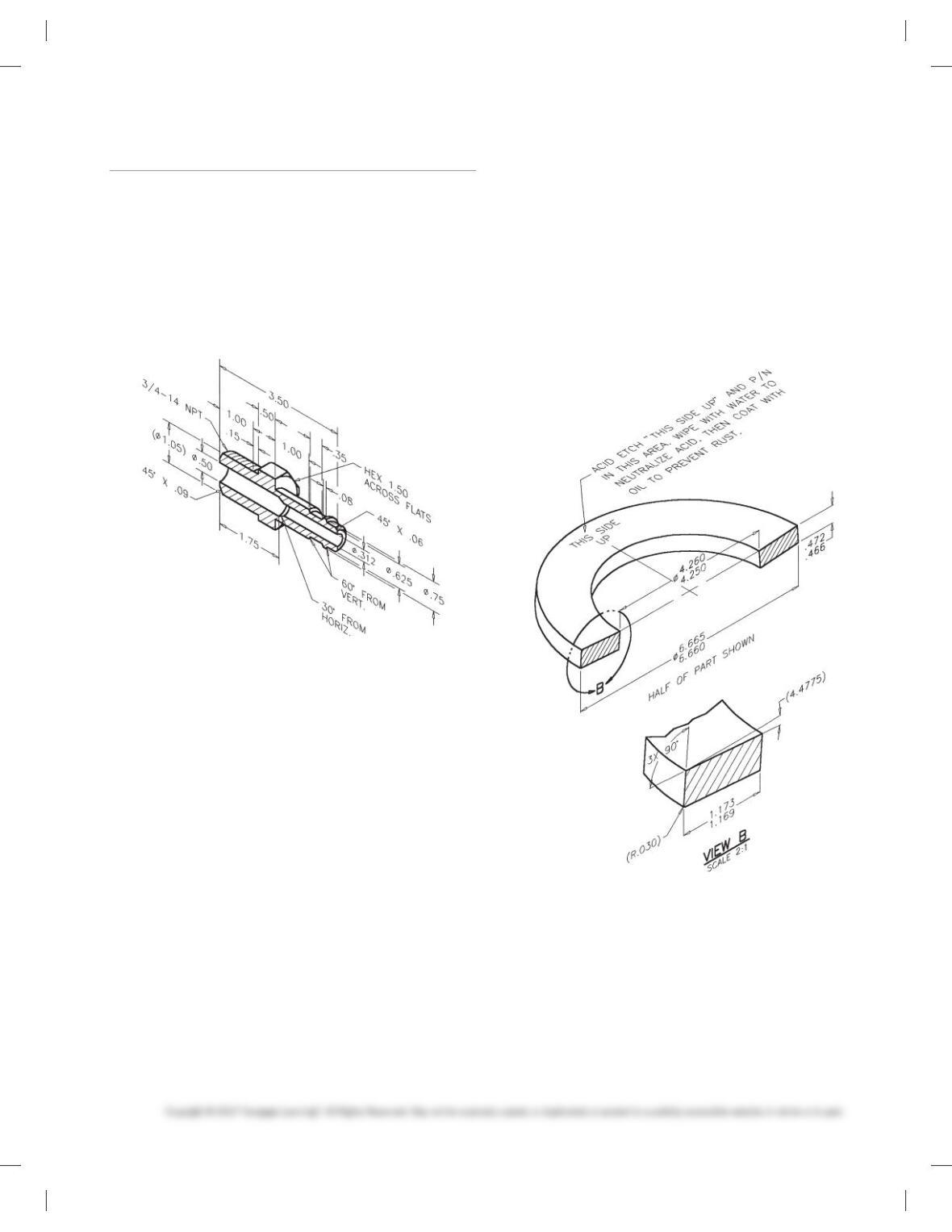
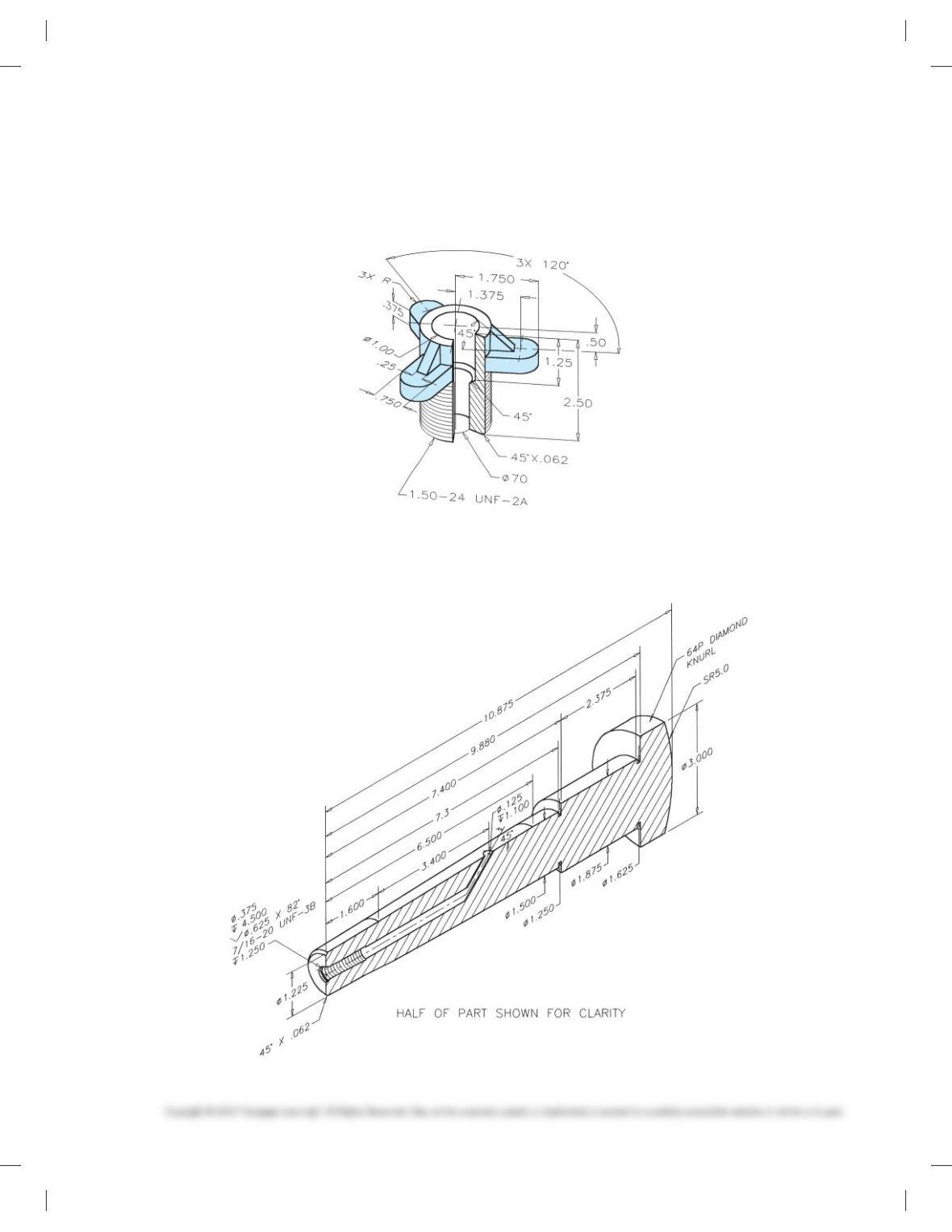
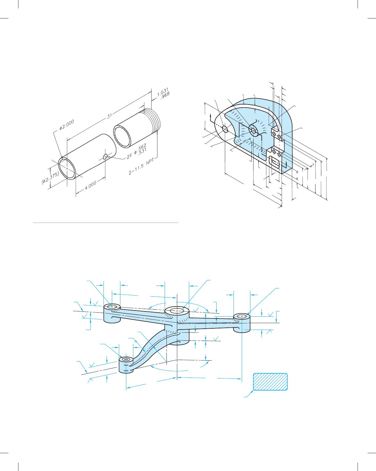
PROBLEM 12.31 Revolved section (in.)
Part Name: End Loading Arm
Material: SAE 2310
Fillets and rounds: R.25
59728_ch12_EOC_ptg01.indd 15 03/02/16 10:27 am
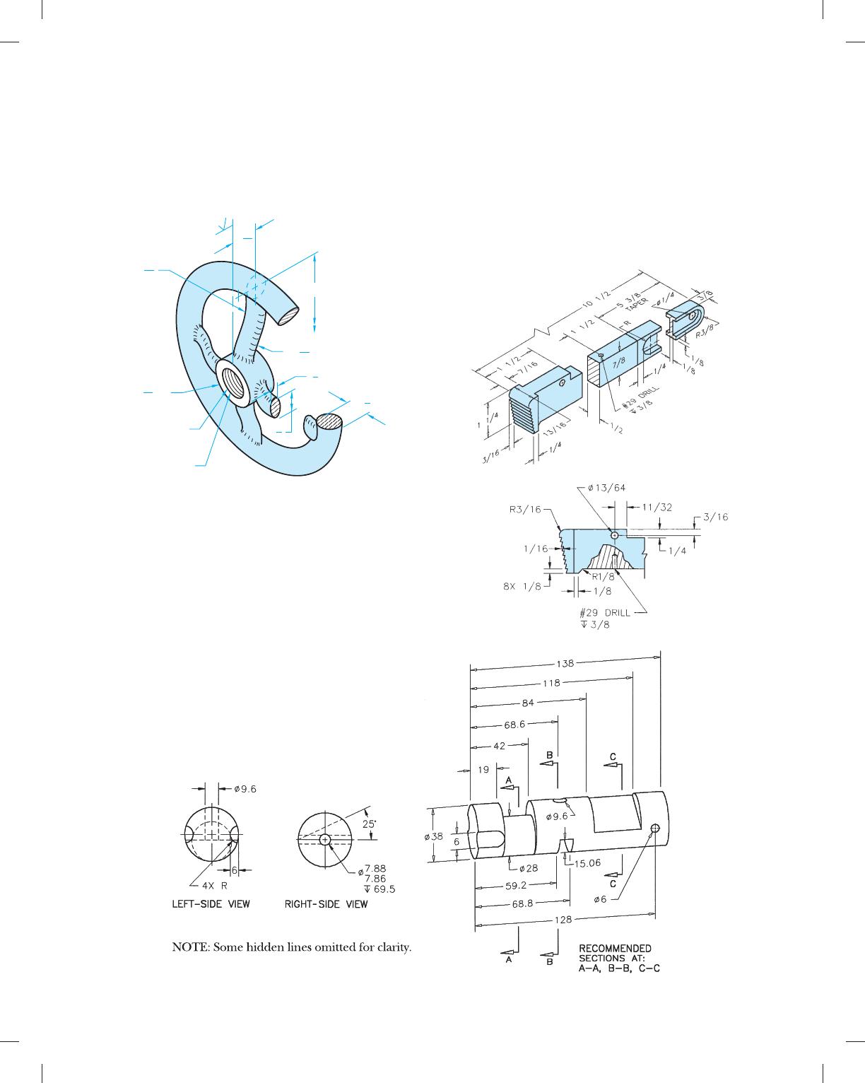
PROBLEM 12.32 Revolved section (in.)
Part Name: Offset Handwheel
Material: Bronze
Fillets and rounds: R.12
Finishes: 125 min.
R1 3
16
R1 3
16
Ø1
Ø8”
3
8
7
8
3
8
23
16
Ø 2.0 X 1 LG
1 – 20 UNEF – 2B
THRU
Ø X .25
1.250
1.252
1
4
PROBLEM 12.33 Broken-out, revolved section, view enlarge-
ment (in.)
Part Name: Pipe Wrench Handle
Material: SAE 5120
Fillets and Rounds: R.06
SPECIFIC INSTRUCTIONS: Engineering sketch is given in fractional
inches. Convert all size dimensions to two-place decimals and loca-
tion dimensions to three-place decimals for final drawing.
PROBLEM 12.34 Removed section (metric)
Part Name: Valve Stem
Material: Phosphor bronze
Finish All Over: 1 mm
59728_ch12_EOC_ptg01.indd 16 03/02/16 10:27 am
PROBLEM 12.35 Offset section (in.)
Part Name: Die Plate Casting
Material: SAE 3120
Fillets and rounds: R.25 unless otherwise specified.
RECOMMENDED CUTTING PLANE
1. 37 1. 1 3 1. 00
.25
.50
2.50
4X Ø .38
Ø .75
.08
OPPOSITE SIDE
2.00
4.38
.88
.88
1.62
R .63
.50
.50
4.63
.25
2 X R .62
ø 1.50
ø 2.25
R.25
1.00
ø .38
ø1.25
.25
1.88
PROBLEM 12.36 Broken-out section (in.)
Part Name: Slide Bar Connector
Material: SAE 4120
SPECIFIC INSTRUCTIONS: Convert chain dimensioning to
datum dimensioning.
PROBLEM 12.37 Broken-out section (in.)
Part Name: Drain Tube
Material: Ø 1.00 × .065
Problem based on original art courtesy TEMCO.
59728_ch12_EOC_ptg01.indd 17 03/02/16 10:27 am
PROBLEM 12.38 Conventional break (in.)
Part Name: Leg
Material: Ø2.00 Schedule 40 A120
Problem based on original art courtesy TEMCO.
PROBLEM 12.39 Offset section (in.)
Part Name: Cover
Material: Cast iron
.28
.69
1.50
1.75
2.75
3.00
3.50
2.50
.28
1.25
2.75
5.50
R1.25
.28
1.22
1.50
.75
1.00
.25
Ø.375
Ø.88
R1.00
Ø.500
R7.00 4X Ø.250
.28
1.00
.25
.75
.25
ALL FILLETS R.19
.25
R1.00
Part 7: Problems 12.40 Through12.51
PROBLEM 12.40 Revolved section, conventional revolution
(in.)
Part Name: Crank Arm
Material: Cast steel 80,000
Fillets and rounds: R.12
CENTERLINE
OF ARM
Ø .313
THRU
Ø1.38
Ø.88
Ø.88
CENTERLINE
OF ARM
CENTERLINE
OF ARM
TYPICAL ARM SECTION
.38 THICK AT HUB
.25 THICK
AT END
R.12
R1.32
Ø.75
.32
.32
.44
.32
.32
.32
.25
.25 1508
1.00
1.63
3.25
3.63
3.50
R1.32
.878
.876
Ø
.440
.437
Ø THRU
.505
Ø.495
THRU
1658
59728_ch12_EOC_ptg01.indd 18 03/02/16 10:27 am
PROBLEM 12.41 You select the sectioning technique (in.)
Part Name: Base Support
Material: Mild steel
PROBLEM 12.42 You select the sectioning technique (in.)
Part Name: Mounting Base
Material: Cast aluminum
59728_ch12_EOC_ptg01.indd 19 03/02/16 10:27 am

PROBLEM 12.43 Full section from actual industry
drawing (in.)
Part Name: Bolt Guard
Material: Aluminum
Courtesy Stanley Hydraulic Tools, a Division of the Stanley Works.
2.960
2.900
1.830
1.770
2.380
2.320
1.430
1.370
28 DRAFT
SECTION A-A
.090
.030
1.000
.940
.280
.220
1. 17 0
1. 110
.270
.210
.330
.270
.780
.720
1.020
.980
.490
.430 .170
.110
158
458
458
458 X
R1.780
1.720
R
.780
.720
R
1.060
1.000
R
1.060
1.000
R
2.780
2.720
R
A
148
A
PROBLEM 12.44 Advanced full section and partial auxi liary
section from actual industry drawing (in.)
Part Name: Accumulator Plug
Material: Phosphor bronze
Courtesy Stanley Hydraulic Tools, a Division of the Stanley Works.
1
2
5 –14UN–2A
PITCH DIA.
11
16 DRILL THRU
3
4–16UNF–2B TO DEPTH SHOWN
1
2
FOR (–B) SAE O-RING PORT
5.330
5.325
Ø
2.440
2.420
.095
.099
4.996
4.992
Ø
5.498
5.488
2.062
1.994
Ø
1.240
1.260
.840
.860
.530
.555
1.250 FULL THD
STEEL STAMP PART NO
IN THIS AREA IN 3/32
CHARACTERS
Ø
4.502
4.498
Ø
Ø1.875
Ø2.630
.750
.760 REF
.480
63
63
R .250
R .016
MAX
.270
17°
30°
.050
.070
45° X
45° X .080
2 PLACES
5.452
5.446
Ø4.125
R.310
R.125
A
A
SECTION A–A
SECTION B–B
B
B
HEX
NOTE: Use dimensioning symbols based on the ASME
Y14.5-2009 standards described in Chapter 10 Dimen-
sioning and Tolerancing. This problem drawing is
based on an outdated standard using abbrevia-
tions and words that should be converted to
symbols as shown in Chapter 10.
59728_ch12_EOC_ptg01.indd 20 03/02/16 10:28 am
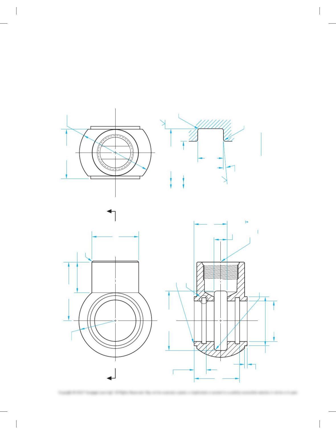
PROBLEM 12.45 Advanced full section and view enlarge-
ment from actual industry drawing (in.)
Part Name: Swivel
Material: SAE 5150
Courtesy Stanley Hydraulic Tools, a Division of the Stanley Works.
2.005
1.995
1.885
1.865
2.250
.450
Ø 2.300
1.720
1.250
.500
R.100 DETAIL B
SCALE: 10 X
SECTION A-A
(1.210)
Ø 1.780
(Ø 2.750)
458 X .020
SEE DETAIL B
BREAK CORNERS R BOTH ENDS
BREAK CORNER
APPROX. R.005
1.375 SPHERICAL
RADIUS
AA
2 X Ø
1. 74 0
1.738
.006
.003
.176
.171
Ø
.015
.005
R
(Ø 1.565)
1.240
1.222
Ø
1.566
1.564
Ø
1
1.200
.095
.085
2 X 5
16 –12UN–2B LH,
.750 FULL THD
FOR–16 (1″) SAE O-
RING PORT
32
63
58
08
59728_ch12_EOC_ptg01.indd 21 03/02/16 10:28 am