
CHAPTER 11 FASTENERS
ANDSPRINGS PROBLEMS
INSTRUCTIONS
1. From the selected problems, determine which views and
dimensions should be used to completely detail the part.
Use simplified representation for thread representations
unless otherwise specified in the instructions or by your
instructor. Use detailed representation for spring represen-
tations unless otherwise specified in the instructions or by
your instructor.
2. Make a multiview sketch to proper proportions, including
dimensions and notes.
3. Using the sketch as a guide, draw an original multiview
drawing on an adequately sized ASME drawing sheet with
border and sheet blocks. Add all necessary dimensions and
notes using unidirectional dimensioning.
4. Include the following general notes at the lower left corner
of the sheet .5 in. each way from the corner border lines:
NOTES:
1. DIMENSIONING AND TOLERANCING PER ASME
Y14.5-2009.
2. REMOVE ALL BURRS AND SHARP EDGES.
Additional general notes can be required, depending on the
specifications of each individual assignment. Use the following
tolerances for unspecified inch values. A tolerance block is
recommended as described in Chapter 2, Drafting Equipment,
Media, and Reproduction Methods, and as shown in problems for
Chapter 10, Dimensioning and Tolerancing, unless otherwise
specified.
Unspecified Tolerances
Decimals mm In.
X6.1
XX 6.01
XXX 6.005
ANGULAR 6309
FINISH 3.2 μm 125 μin.
For metric drawings, provide a general note that states TOLER-
ANCES FOR UNSPECIFIED DIMENSIONS COMPLY WITH ISO
2768-m. Provide a general note that states SURFACE FINISH
3.2μm UNLESS OTHERWISE SPECIFIED.
59728_ch11_EOC_ptg01.indd 2 03/02/16 10:27 am
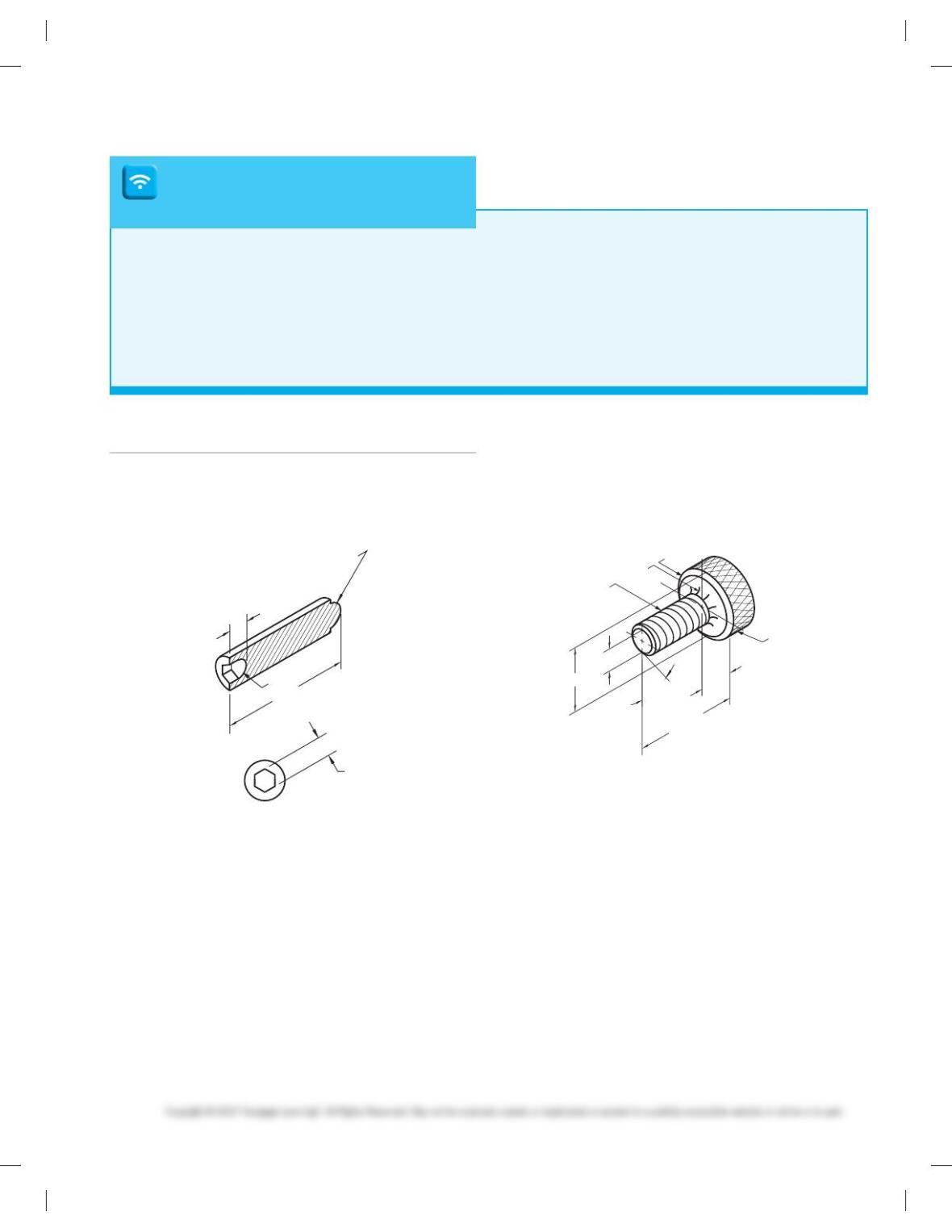
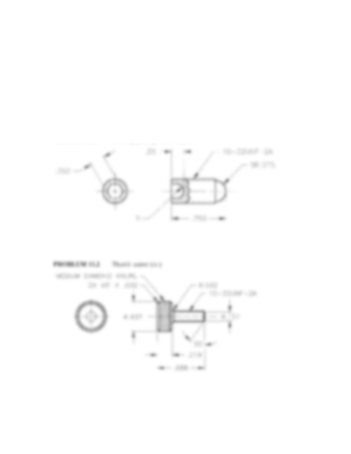
PROBLEM 11.2 (in.)
Part Name: Thumb Screw
Material: SAE 1315 steel
.688
R.032
10-32 UNF-2A
358
2X 458 X .032
Ø.437 Ø.151
.219
64P KNURL
To access CADD template files with predefined drafting
settings, go to the Student Companion Website, select
Student Downloads, Drafting Templates, and then the
appropriate template file. Use the templates to create new
designs, as a resource for drawing and model content, or
for inspiration when developing your own templates. The
ASME-Inch and ASME-Metric drafting templates follow
ASME, ISO, and related mechanical drafting standards.
Drawing templates include standard sheet sizes and
formats, and a variety of appropriate drawing settings and
content. You can also use a utility such as the AutoCAD
DesignCenter to add content from the drawing templates
to your own drawings and templates. Consult with your
instructor to determine which template drawing and
drawing content to use.
DRAFTING TEMPLATES
Part 1: Problems 11.1 Through 11.24
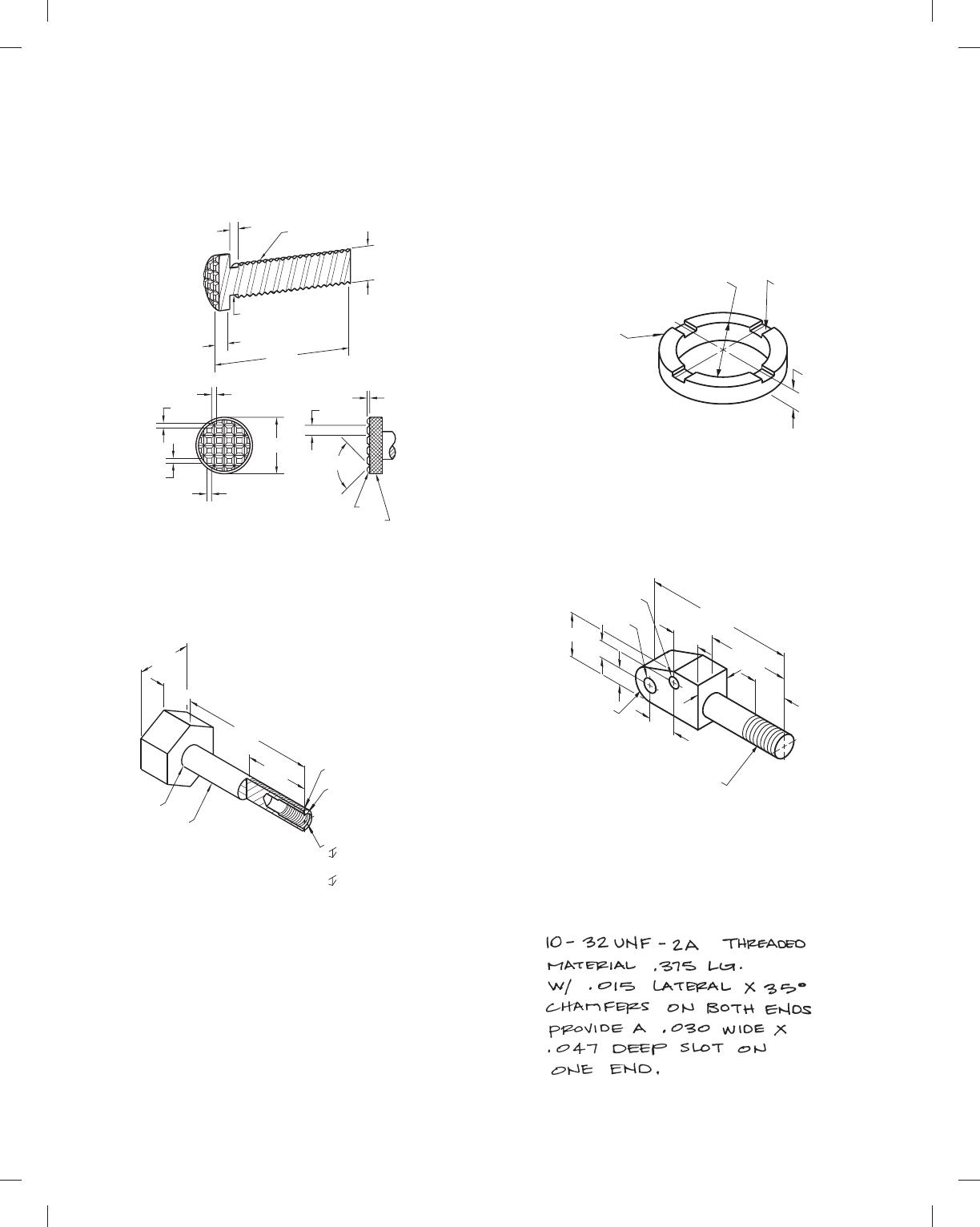
PROBLEM 11.1 (in.)
Part Name: Full Dog Point Gib Screw
Material: 10-32 UNF-2A .75 long
.25
.120
SR.075
SIDE VIEW
.750
.125
59728_ch11_EOC_ptg01.indd 3 03/02/16 10:27 am
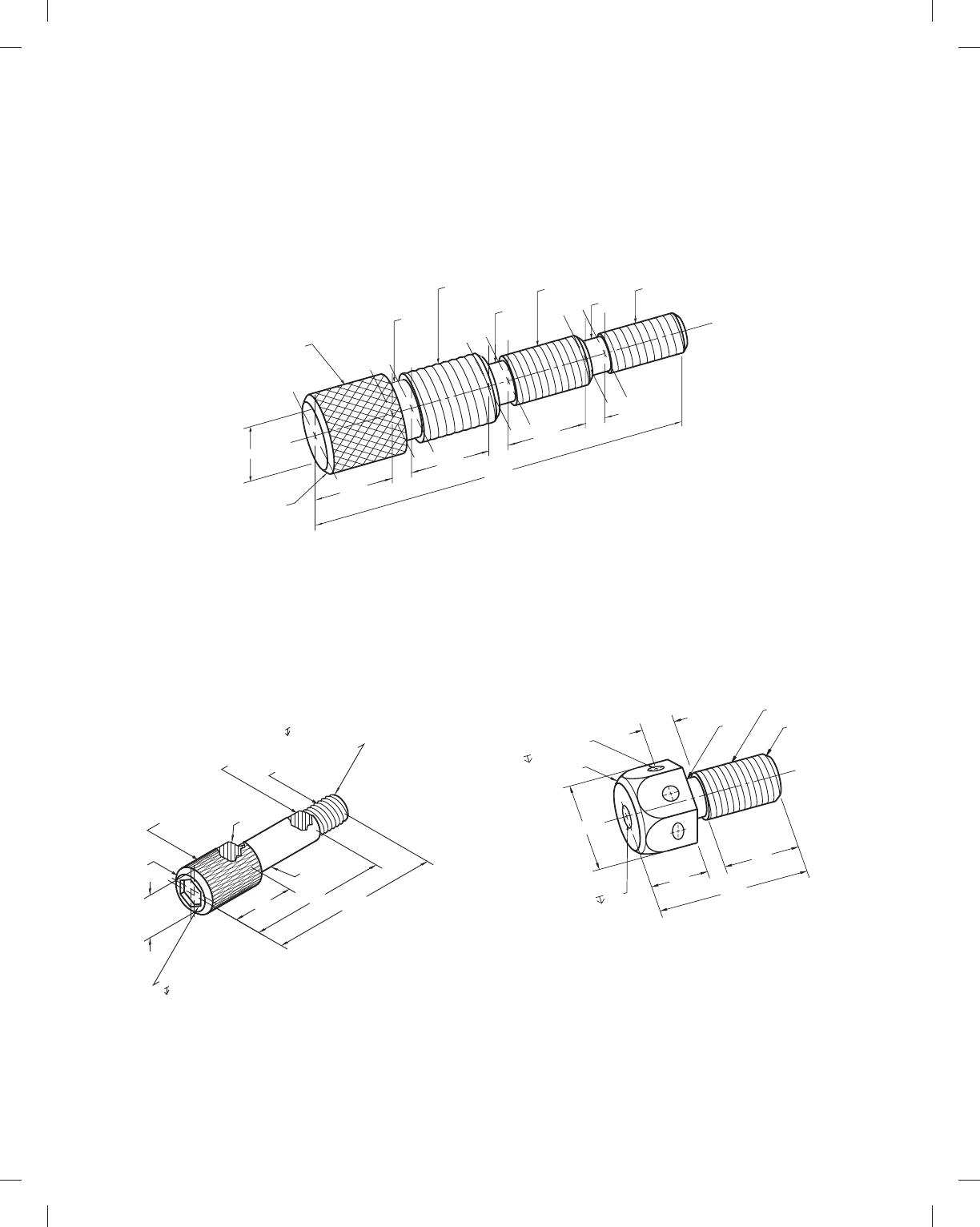
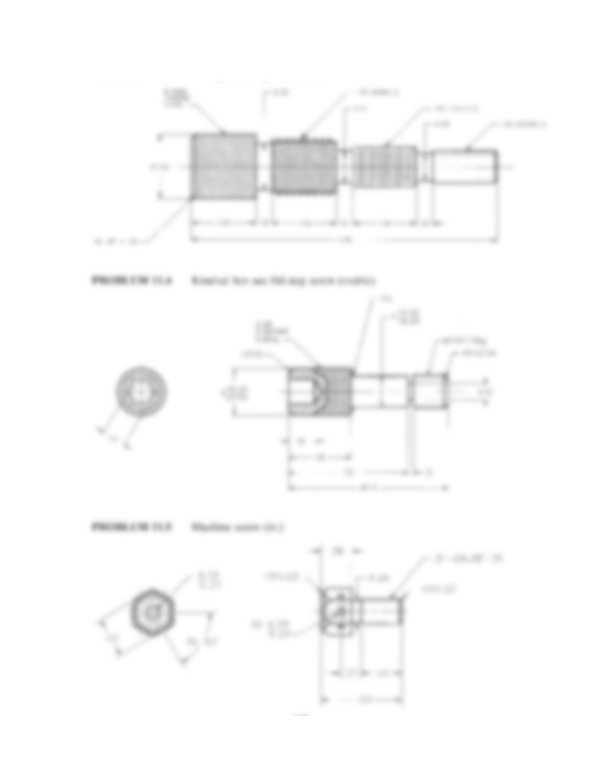
PROBLEM 11.3 (in.)
Part Name: H-Step Threading Screw
Material: SAE 3130
SPECIFIC INSTRUCTIONS: Draw each of the three threads using
the representation specified below each thread note.
PROBLEM 11.5 (in.)
Part Name: Machine Screw
Material: Stainless steel
Finish All Over: 2 μm
6X Ø.08
.25 (6X 60
8
)
45
8
X .03
Ø.15
.31
Ø.26 .31-24 UNF-3A
45
8
X .03
.50
1.00
.50
.38
.25
PROBLEM 11.4 (metric)
Part Name: Knurled Hex Soc Head Step Screw
Material: SAE 1040
Case Harden: 1.6-mm deep per Rockwell C scale
Finish: 2 μm; black oxide
Ø
R3.05
NECK 3W X Ø4.06
M20 X 6g
45
8
X 2.54
HEX. SOCK. HD.
16 ACROSS FLATS
0.8P DIAMOND
KNURL
45
8
X 3
97.5
73
38 18.99
19.02
28.52
28.58
16
Ø
Ø.72
Ø.51
Ø.43
KNURL
DIAMOND
MEDIUM
.87-9 UNC-2A
(SHOW IN DETAIL
REPRESENTATION)
(SHOW IN SCHEMATIC)
.62-11 UNC-2A
SIMPLIFIED)
(SHOW IN
.50-20 UNC-2A
45
8
X .06
4X
1.00
4.75
.25
1.00 1.00
.25
.25
Ø1.00
59728_ch11_EOC_ptg01.indd 4 03/02/16 10:27 am
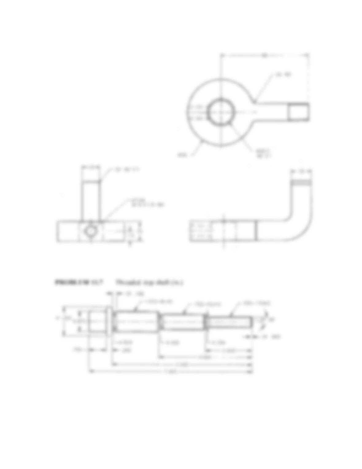
PROBLEM 11.6 (metric)
Part Name: Lathe Dog
Material: Cast iron
Ø7.94
M10 X 1.5-5H
Ø20.5
45
8
X 1
Ø50
2X R3
R6
2X 45
8
X 1
R20
15
66
15
7.5
45
13
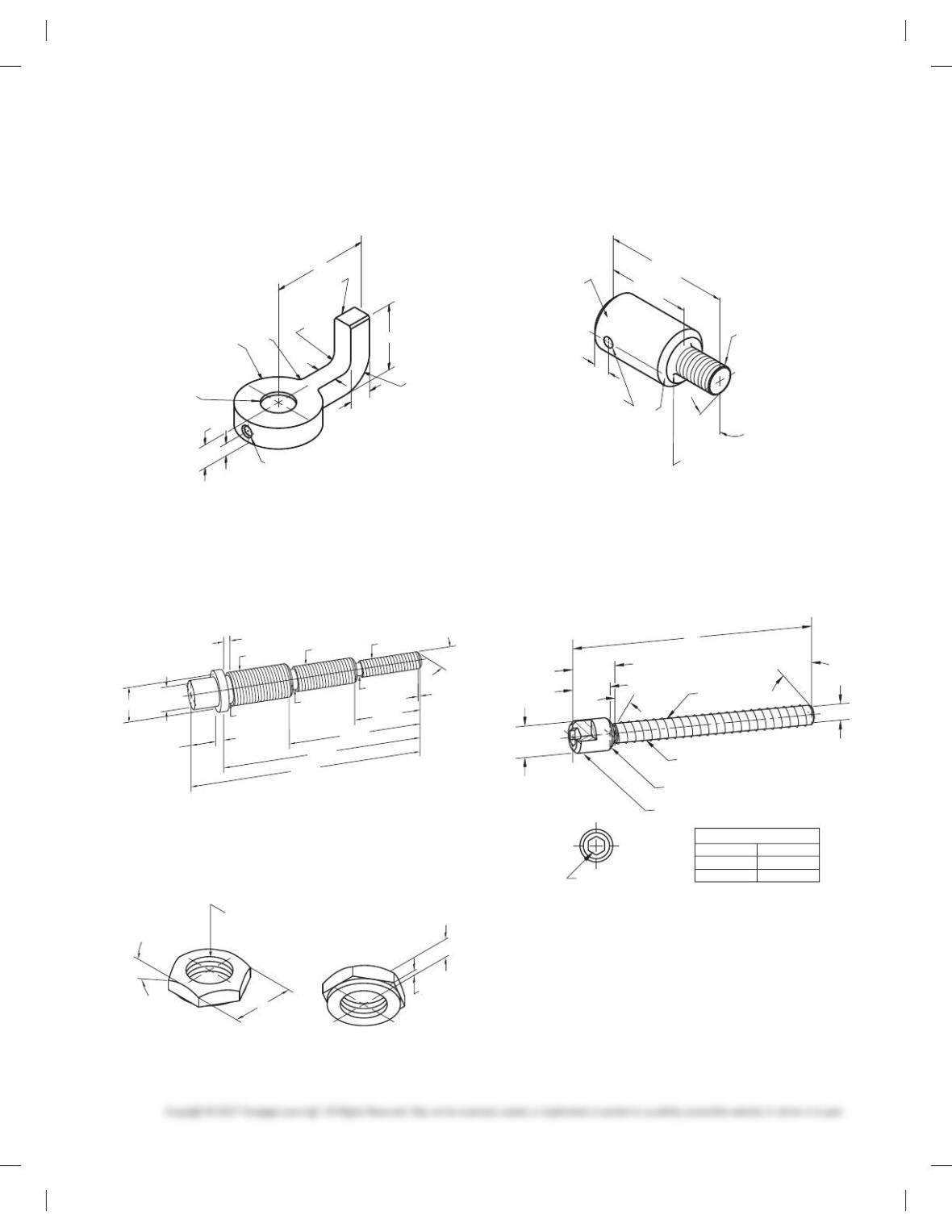
PROBLEM 11.7 (in.)
Part Name: Threaded Step Shaft
Material: SAE 1030
Ø.824
Ø.605 Ø.384
1.000-8 UNC .750-10 UNC .500-13 UNC
3X 30
8
Ø.875
Ø1.250
.750
.250
3X .188
3X .063
2.000
4.000
6.000
7.000
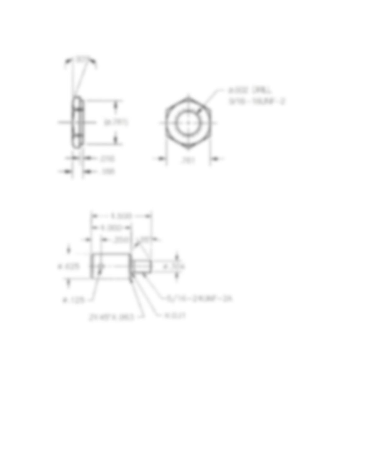
PROBLEM 11.8 (in.)
Part Name: Washer Face Nut
Material: SAE 1330 steel
Ø.502 DRILL
.781
30
8
9/16-18 UNF-2B
.016
.188
BOTTOM
VIEW
PROBLEM 11.9 (in.)
Part Name: Shoulder Screw
Material: SAE 4320 steel
5/16-24 UNF-2A
R.031
2X 458 X .063
.250
Ø.625
Ø.125
358
1.500
1.000
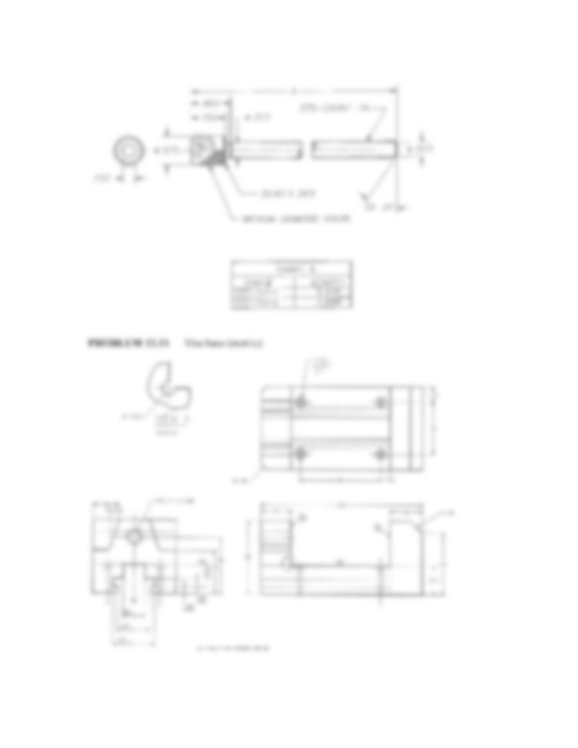
PROBLEM 11.10 (in.)
Part Name: Stop Screw
Material: SAE 4320
Hex Depth: .175
Note: Medium diamond knurl at head
.850
A
.750
358
Ø.313
2X 458 X .063
3/8-24 UNF-2A
Ø.323
Ø.625
5/16 HEX
CHART A
PART #
1DT-1011
1DT-1012
LENGTH
4.438
3.688
35
8
MEDIUM DIAMOND KNURL
59728_ch11_EOC_ptg01.indd 5 03/02/16 10:27 am
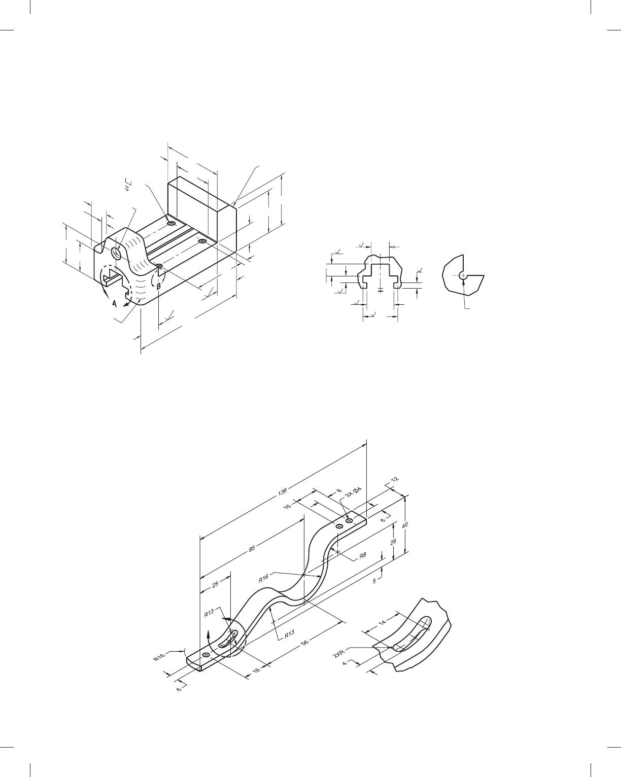
PROBLEM 11.11 (metric)
Part Name: Vise base
Material: Cast iron
21
.5
4X Ø 3
Ø7
2
42 32
6
19
11.5
62
39
46 55
24
120
22
45
8
60 7
6X R6
M12 X 1.75-6H
32 32
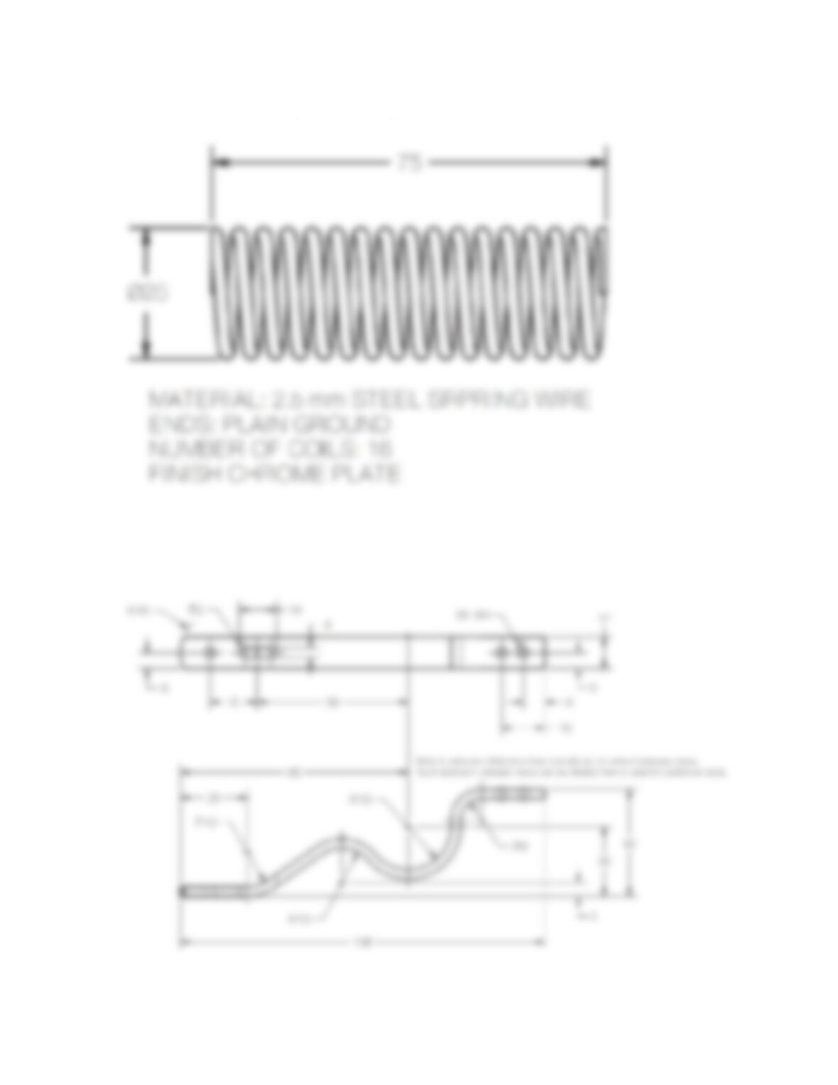
PROBLEM 11.12 (metric)
SPECIFIC INSTRUCTIONS: Create spring drawing based on the
following specifications:
Part Name: Compression Spring
Material: 2.5-mm steel spring wire
Ends: Plain ground
Outside Diameter: 25
Free Length: 75
Number of Coils: 16
Finish: Chrome plate
DETAIL B
2X R0.6
(THRU BOTH SIDES)
DETAIL A
24
31
63
5
63
16
6
10.5
63
63
63
63
PROBLEM 11.13 (metric)
Part Name: Flat Spring
Material: 3.5-mm spring steel
Finish: Black oxide
Heat Treat: 1-mm deep Rockwell C scale
A
DETAIL A
SCALE 2 : 1
59728_ch11_EOC_ptg01.indd 6 03/02/16 10:27 am
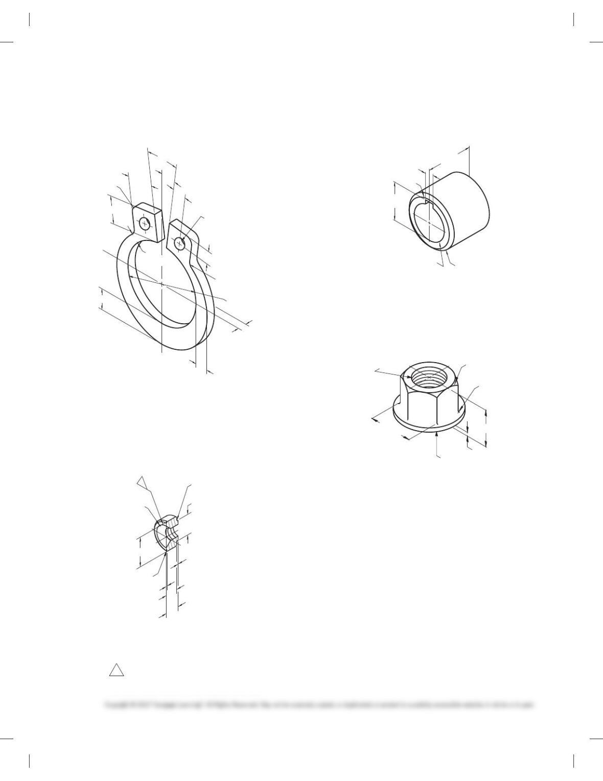
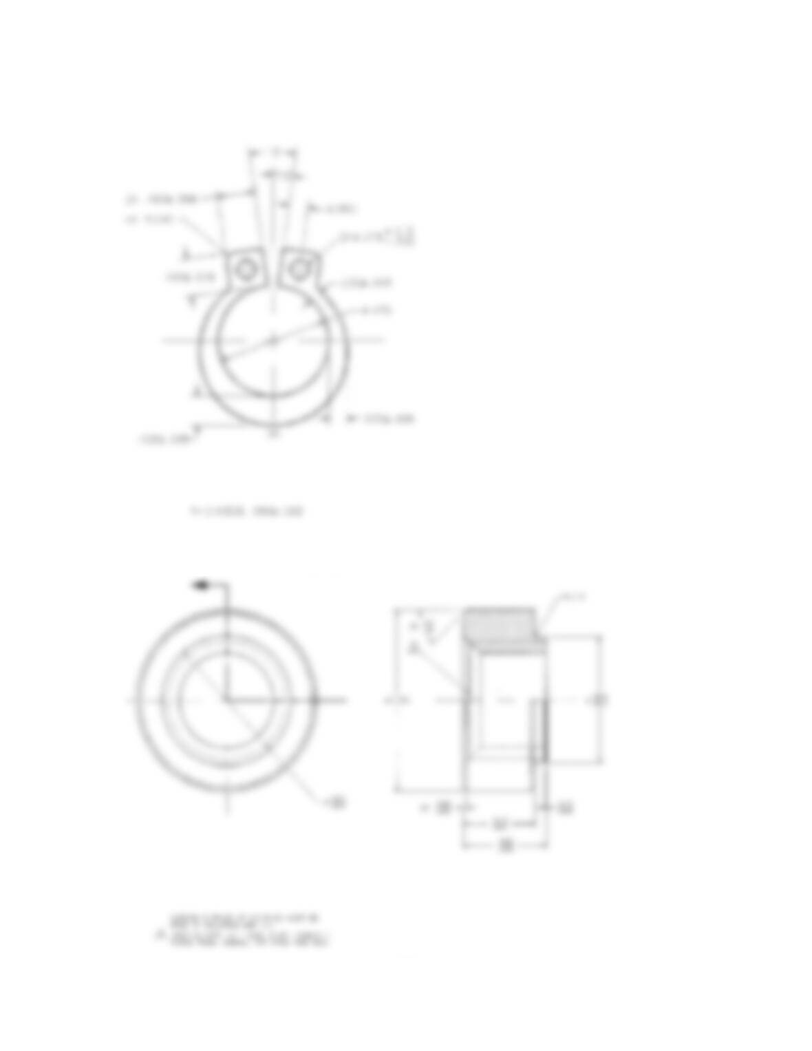
PROBLEM 11.14 (in.)
Part Name: Retaining Ring
Material: Stainless steel
.160
6
.008
.050
6
.008
.160
6
.008
4X R.040
.075
6
.008
Ø.470
.125
6
.008
7. 5
8
15
8
.080
2X Ø.078 -.002
+.015
.080
.050
6
.002
2X R.040
PROBLEM 11.15 (in.)
Part Name: Half Coupling
Material: Ø1.250 C1215 steel
Problem based on original art courtesy TEMCO.
TURNS FROM NOMINAL. TAP FROM THIS END.
.500-14 NPTF: L-1 GAGE, PLUS 1/MINUS 1
2
47
8
43
8
HALF OF PART SHOWN FOR CLARITY.
OUTSIDE SURFACE OF COUPLING MUST BE
.015
.005
R.015
.850
.865
FREE OF OXIDIZATION AND INK.
.045
.025
.580
.560
.510
.490
.891
.922
Ø
2
4X
2X
Ø1.250
Ø
PROBLEM 11.16 (in.)
Part Name: Collar
Material: SAE 1020
Ø1.498-.000
+.003
2X 45
8
X .125
Ø2.250
2.000
1. 6 6 9
.375
.379
1. 6 7 9
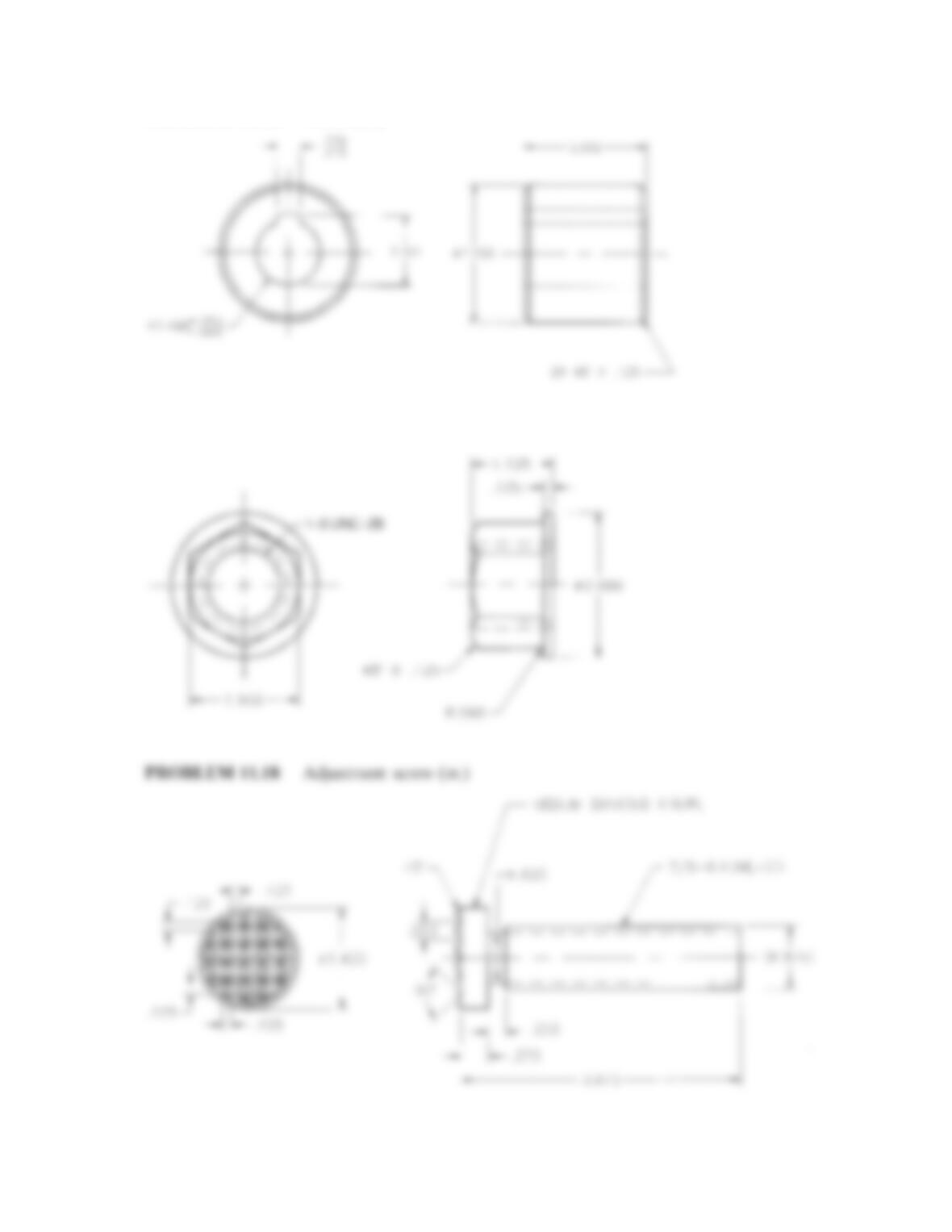
PROBLEM 11.17 (in.)
Part Name: Bearing Nut
Material: SAE 1040
1. 12 5
.125
45
8
X .125
1-8 UNC-2B
R.06
Ø2.000
(FLATS)
1. 5 0 0
59728_ch11_EOC_ptg01.indd 7 03/02/16 10:27 am
PROBLEM 11.18 (in.)
Part Name: Adjustment Screw
Material: SAE 2010 steel
Ø.690
7/8-6-ACME-2G
(Ø.875)
3.873
.373
.062
1. 4 0 0
.125
.125
458
908
.125 .250
0.125
MEDIUM DIAMOND KNURL
.250
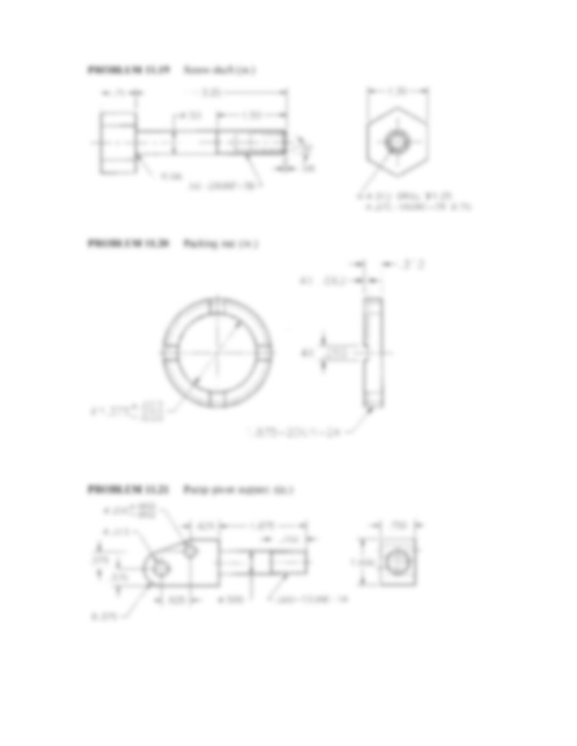
PROBLEM 11.19 (in.)
Part Name: Screw Shaft
Material: 3/4 hex 3 4 1/8 stock mild steel
R.06
1. 5 0
3.25
.75
30
8
X .06 (HORIZ)
.50-20 UNF-3B
Ø.50
1. 2 5
.375-16 UNC-2B
.75
Ø.312
1. 3 0
PROBLEM 11.20 (in.)
Part Name: Packing Nut
Material: Bronze
A: Spanner slots .250 wide 3 .063 deep.
Ø1.375
-.000
+.002
1.875-20 UNF-2A
4X A
A: SLOT WIDTH .250
SLOT DEPTH .063
THREADS NOT SHOWN
.313
PROBLEM 11.21 (in.)
Part Name: Pump Pivot Support
Material: Cold rolled mild steel
R.375
Ø.313 THRU
THRU
-.002
+.000
Ø.250
3.500
.750
.375
.625
.625
1. 8 7 5
.750
.375
1. 0 0 0
.500-13 UNC-1A
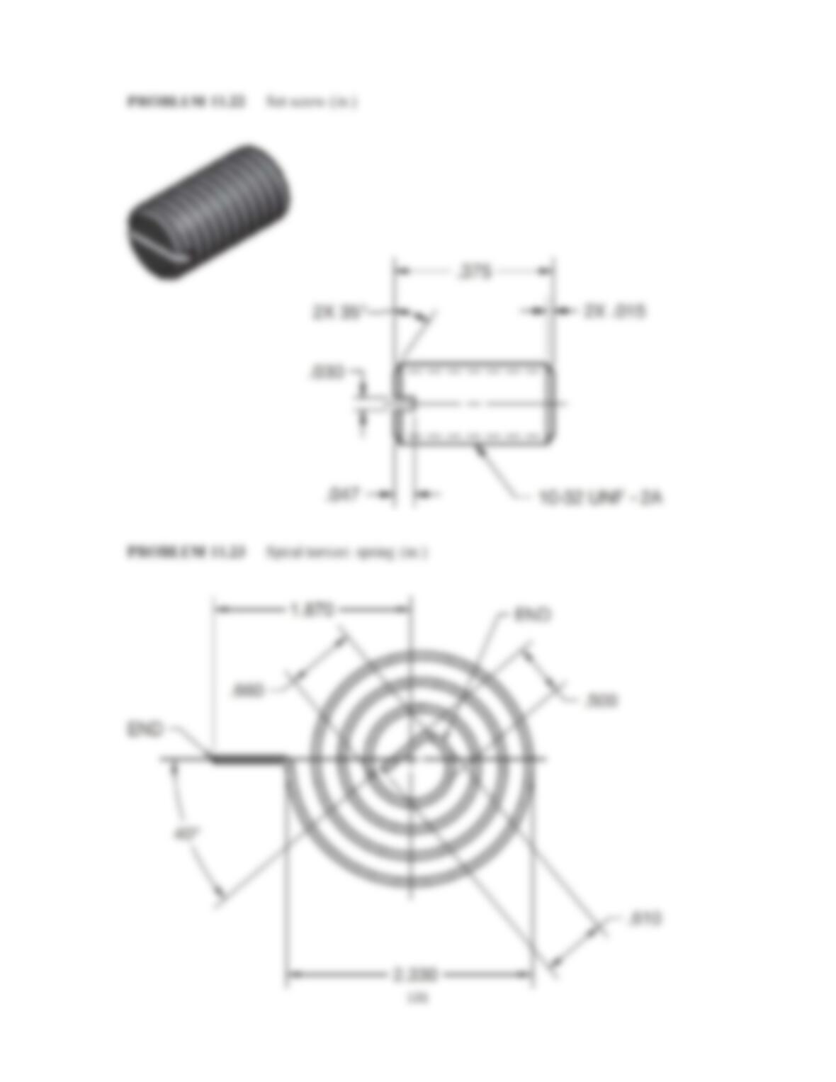
PROBLEM 11.22 (in.)
Part Name: Set Screw
Material: Steel
SPECIFIC INSTRUCTIONS: Prepare a detailed drawing from the
written instructions below.
59728_ch11_EOC_ptg01.indd 8 03/02/16 10:27 am
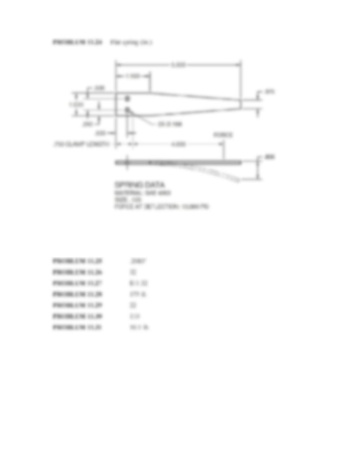
1.000
.375
.750 CLAMP LENGTH
1.500
5.500
4.000
.806
.500
.250
.500
SPRING DATA
MATERIAL: SAE 4063
SIZE: .125
FORCE AT DEFLECTION: 10,000 PSI
2X Ø.188
FORCE
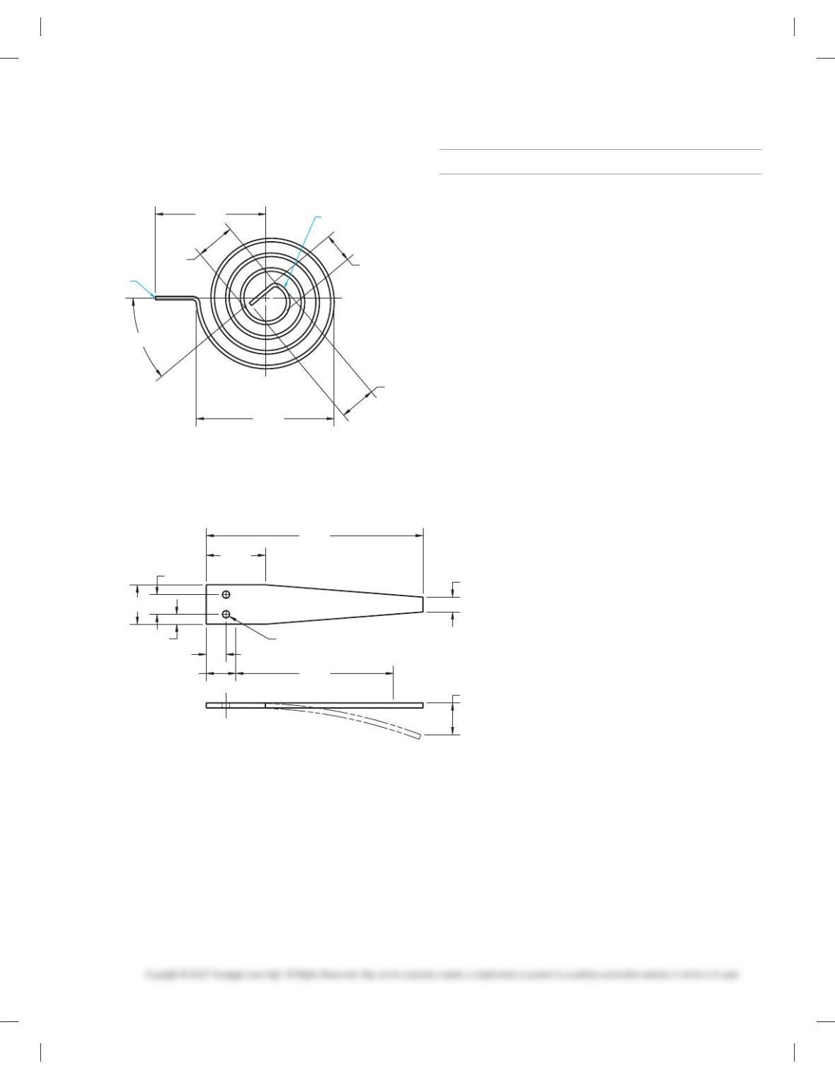
PROBLEM 11.23 (in.)
Part Name: Spiral Torsion Spring
Material: SAE 1060
2.330
.610
.660
40°
.500
1.870 END
END
PROBLEM 11.24 (in.)
Part Name: Flat Spring
Material: SAE 4063
MATH PROBLEMS
Part 2: Problems 11.25 Through 11.31
PROBLEM 11.25 The taper of a pin is .5:12. What would be
the taper for a 5 in. long pin?
PROBLEM 11.26 A lathe operator turns out 9 brass bushings
in 2 hours 15 minutes. At the same rate, how many bushings can
be turned in 8 hours?
PROBLEM 11.27 Seventeen drills cost $27.50. What would
seven drills cost?
PROBLEM 11.28 The scale on a landscape map is 1:50. If two
points on the map are 3.50 apart, what is the actual distance be-
tween the two points?
PROBLEM 11.29 A crew of twelve people assembles 45 units
a day. If production is to be increased to 80 units per day, how
many people will be needed?
PROBLEM 11.30 If five dozen shop cloths are enough for six
mechanics, how many cloths will be needed for eleven
mechanics?
PROBLEM 11.31 A shop manual chain hoist requires a 22-lb
pull to lift one ton (2000 lb). How much pull would it take to lift a
1500-lb load
59728_ch11_EOC_ptg01.indd 9 03/02/16 10:27 am
122
Chapter 11
Fasteners and Springs
Solutions to End-of- Chapter Problems
(Note: Problem solutions are provided without border and sheet blocks, which should be
included in student drawings.)
Part 1: Problems 11.1 Through 11.24
PROBLEM 11.1 Full dog point gib screw (in.)
123
PROBLEM 11.3 H-Step threading screw (in.)
124
PROBLEM 11.6 Lathe dog (metric)
125
PROBLEM 11.8 Washer face nut (in.)
PROBLEM 11.9 Shoulder screw (in.)
126
PROBLEM 11.10 Stop screw (in.)
127
PROBLEM 11.12 Compression spring (metric)
PROBLEM 11.13 Flat spring (metric)
128
PROBLEM 11.14 Retaining ring (in.)
PROBLEM 11.15 Half coupling (in.). Courtesy TEMCO.
129
PROBLEM 11.16 Collar (in.)
PROBLEM 11.17 Bearing nut (in.)
130
132
Math Problem Solutions
Part 2: Problems 11.25 Through 11.31