Chapter 6 Lines and Lettering : Problems 6.1 through 6.11.
Chapter 7 Drafting Geometry: Problems 7.21 through 7.43.
Chapter 8 Multiviews: Problems 8.58 through 8.89.
Chapter 9 Auxiliary Views: Problems 9.15 through 9.37.
Instructions
1. From the selected sketch, determine which view should be
the front view. Then determine which other views, if any,
you need to draw to fully display the part in a multiview
drawing. Use an auxiliary view or views if needed to fully
describe the part.
2. Make a multiview sketch of the selected problem as close to
correct proportions as possible. Be sure to indicate where
you intend to place the dimension lines, extension lines, ar–
rowheads, and hidden features to help you determine the
spacing for your final drawing.
3. Using the sketch you have just developed as a guide, make
an original multiview drawing on an adequate size drawing
sheet and at an appropriate scale. Include all dimensions
needed using unidirectional dimensioning. From the se-
lected problems, determine which views and dimensions
should be used to completely detail the part.
4. Include the following general notes at the lower-left corner
of the sheet .5 in. each way from the corner border lines:
NOTES:
1. DIMENSIONING AND TOLERANCING PER ASME Y14.5-2009.
2. REMOVE ALL BURRS AND SHARP EDGES.
Additional general notes may be required, depending on the
specifications of each individual assignment. Use the following
tolerances for unspecified inch values. A tolerance block is rec-
ommended as described in Chapter2.
Unspecified Tolerances
Decimals In.
X6.1
XX 6.01
XXX 6.005
ANGULAR 6309
FINISH 125 µin.
For metric drawings, provide a general note that states:
TOLERANCES FOR UNSPECIFIED DIMENSIONS COMPLY
WITH ISO 2768-m. Provide a general note that states: SURFACE
FINISH 3.2 µm UNLESS OTHERWISE SPECIFIED.
Each problem assignment is given as an engineer’s layout
to help simulate actual drafting conditions. Initial problems
provide a suggested layout and problems become more complex
as you continue.
Dimensions and views on engineers’ layouts may not be
placed in accordance with acceptable standards. You need to
carefully review the chapter material when preparing the layout
sketch. In some problems, the engineer’s layout certain informa-
tion, such as the symmetry of a part or the alignment of holes.
You need to place enough dimensions or draw lines between
features to dimension the part.
To access CADD template files with predefined drafting
settings, go to the Student Companion Website, select
Student Downloads, Drafting Templates, and then
select the appropriate template file. Use the templates
to create new designs, as a resource for drawing and
model content, or for inspiration when developing your
own templates. The ASME-Inch and ASME-Metric
drafting templates follow ASME, ISO, and related
mechanical drafting standards. Drawing templates
include standard sheet sizes and formats, and a variety
of appropriate drawing settings and content. You can also
use a utility such as the AutoCAD DesignCenter to add
content from the drawing templates to your own
drawings and templates. Consult with your instructor to
determine which template drawing and drawing content
to use.
DRAFTING TEMPLATES
59728_ch10_EOC_ptg01.indd 3 03/02/16 10:26 am
yyg
CHAPTER 10 DIMENSIONING
AND TOLERANCING PROBLEMS
PROBLEMS CONTINUED FROM
PREVIOUS CHAPTERS
In addition to the problems found in this chapter, you can go back
to the previous chapters listed here and complete the drawings by
adding the given dimensions. Open the existing drawing and edit
views by moving to accommodate dimension placement.
BASIC PROBLEMS
Part 1: Problems 10.1 Through 10.20
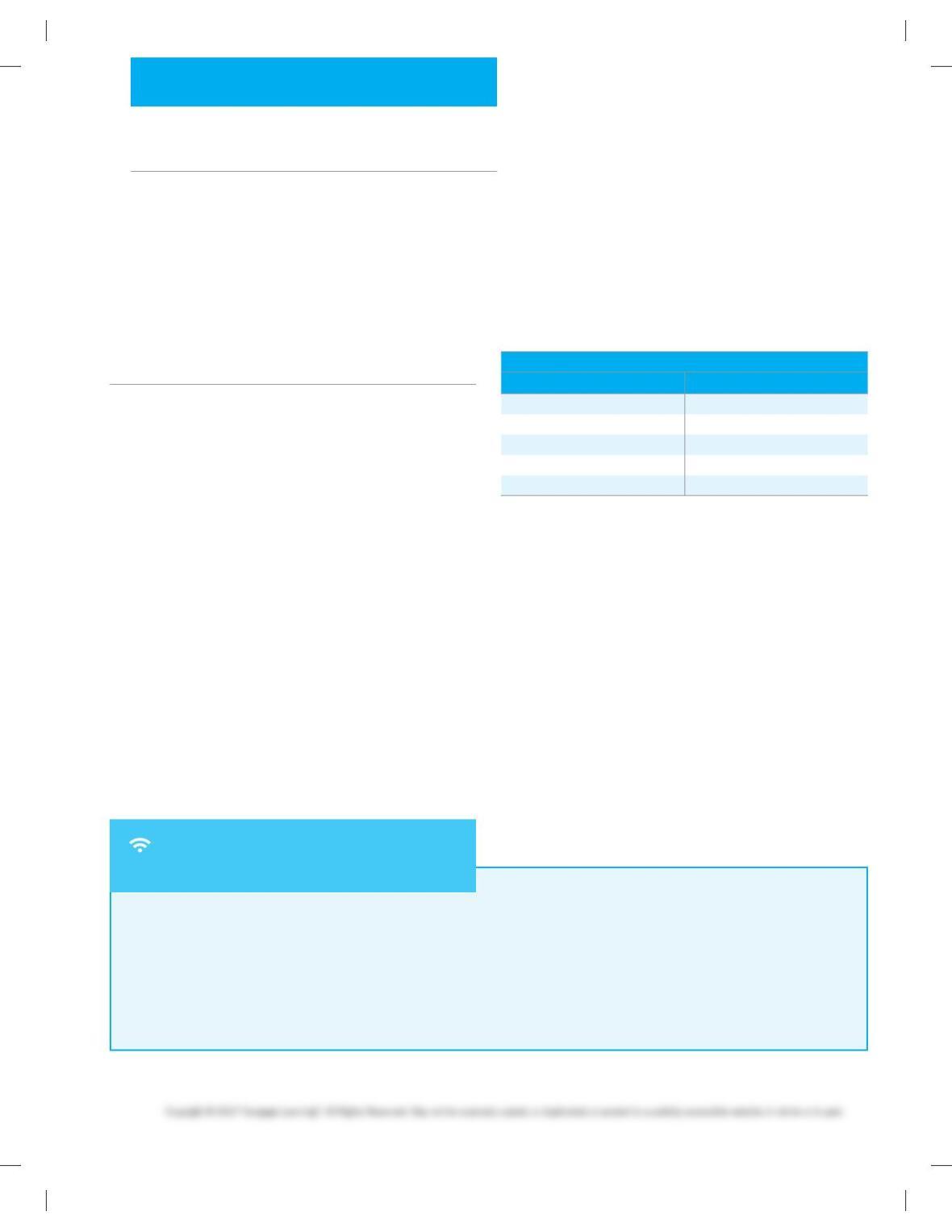
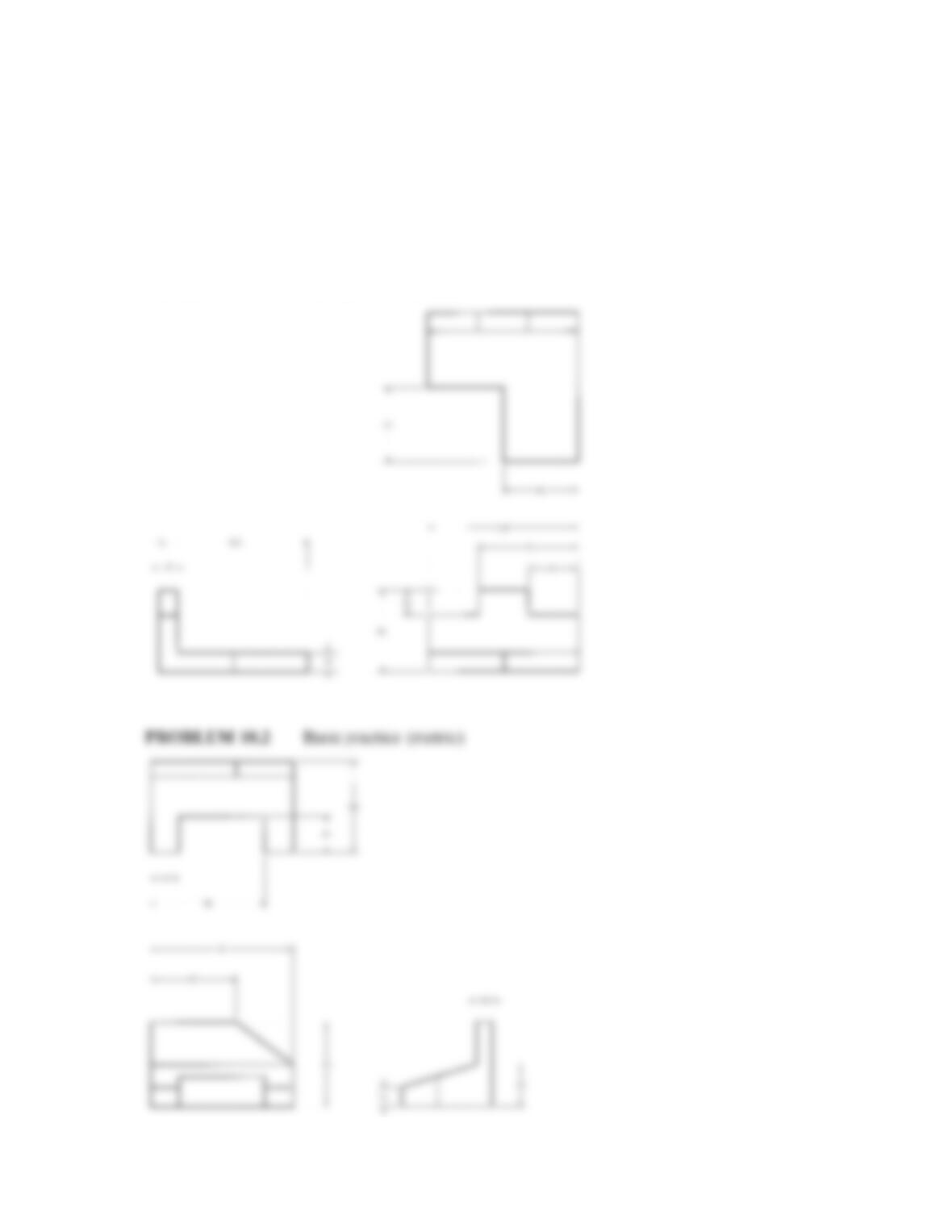
PROBLEM 10.1 Basic Problems (metric)
Part Name: Step
Block Material: SAE 1020
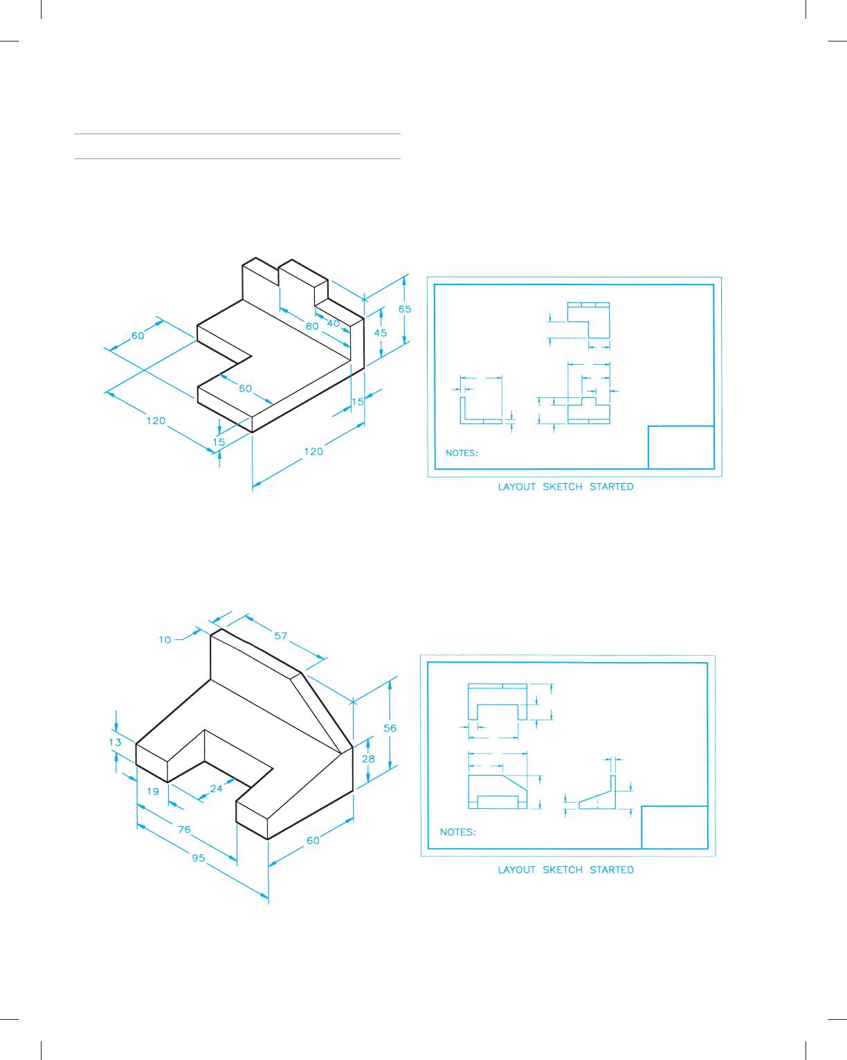
PROBLEM 10.2 Basic practice (metric)
Part Name: Machine Tool Wedge
Plate Material: SAE 4320
59728_ch10_EOC_ptg01.indd 4 03/02/16 10:26 am
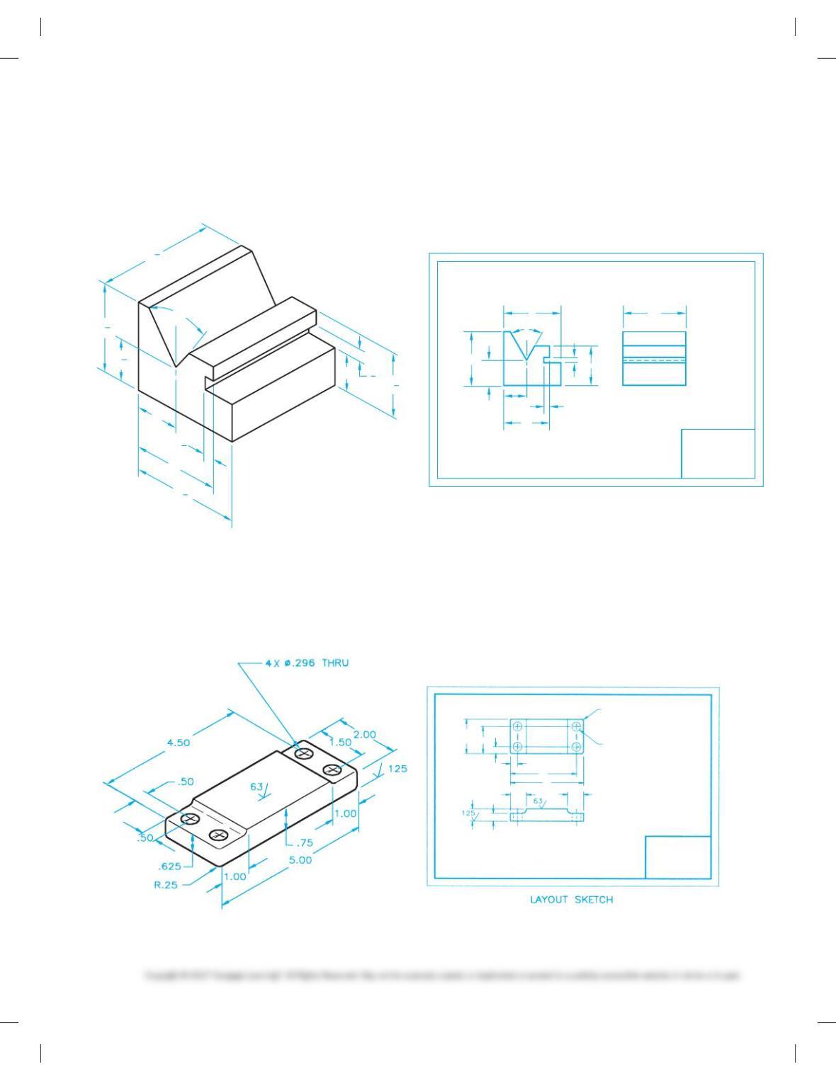
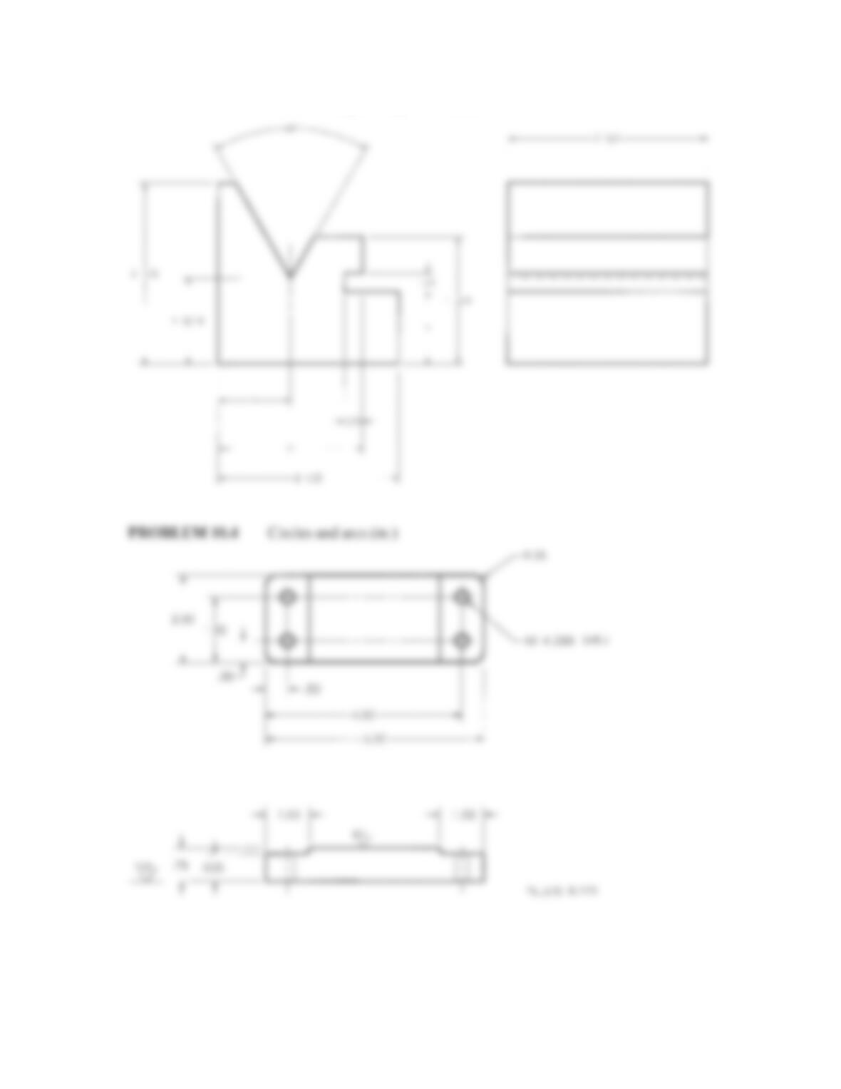
PROBLEM 10.3 Dimensioning basic practice (in.)
Part Name: V-guide
Material: SAE 4320
Fractions: 61/32
23
4
21
2
1
1
1
2
LAYOUT SKETCH
OPTIONAL SINGLE VIEW WITH LENGTH
GIVEN IN GENERAL NOTE OR TITLE BLOCK
3
16
13
4
21
2
1
4
1
4
608
PROBLEM 10.4 Circles and arcs (in.)
Part Name: Rest Pad
Material: SAE 1040
Fillets: R.125
59728_ch10_EOC_ptg01.indd 5 03/02/16 10:26 am
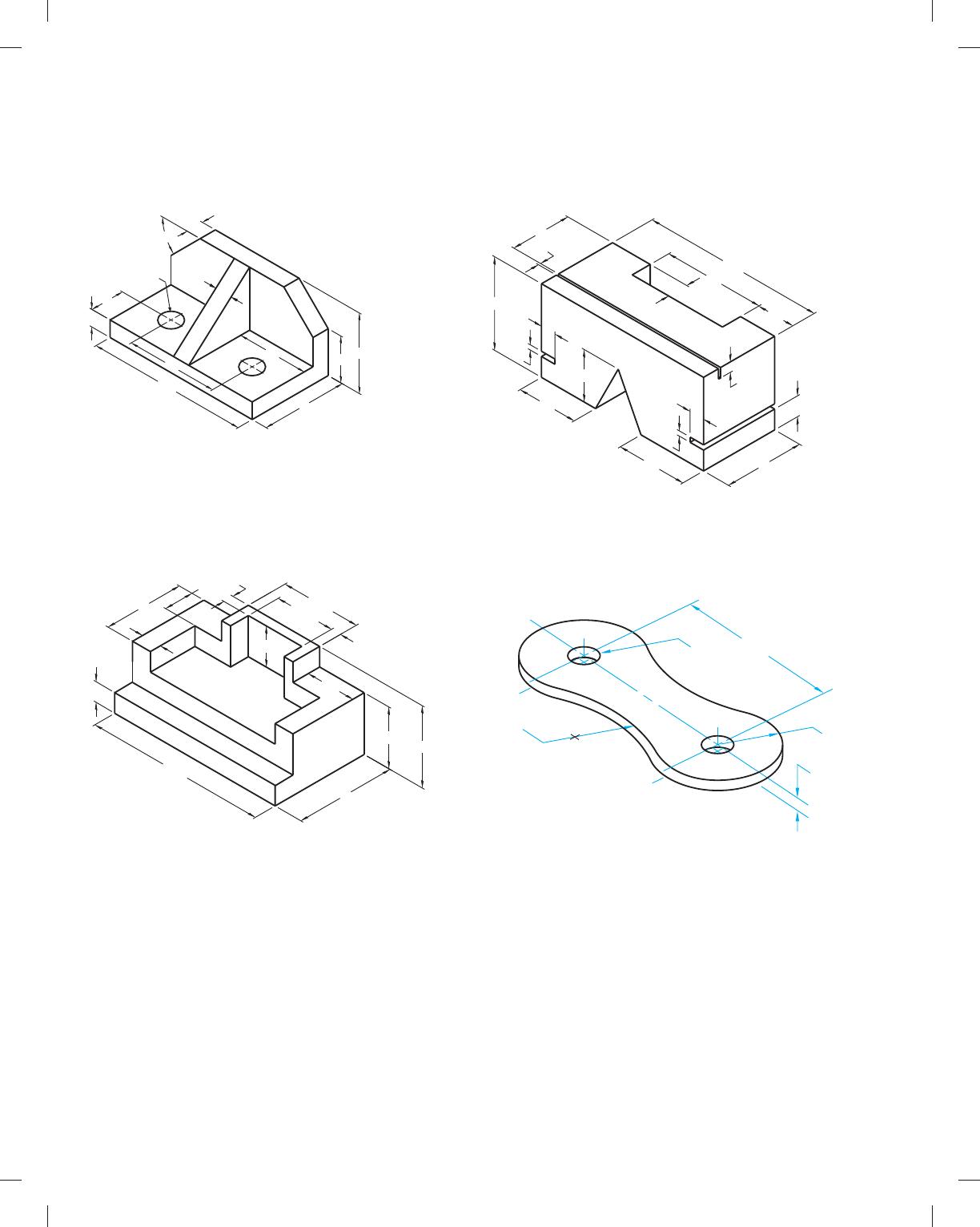
PROBLEM 10.5 Limited space (metric)
Part Name: Angle Bracket
Material: Mild steel (MS)
2X Ø15
2X45° 55
12
112
64
24
12
12
60
32
50
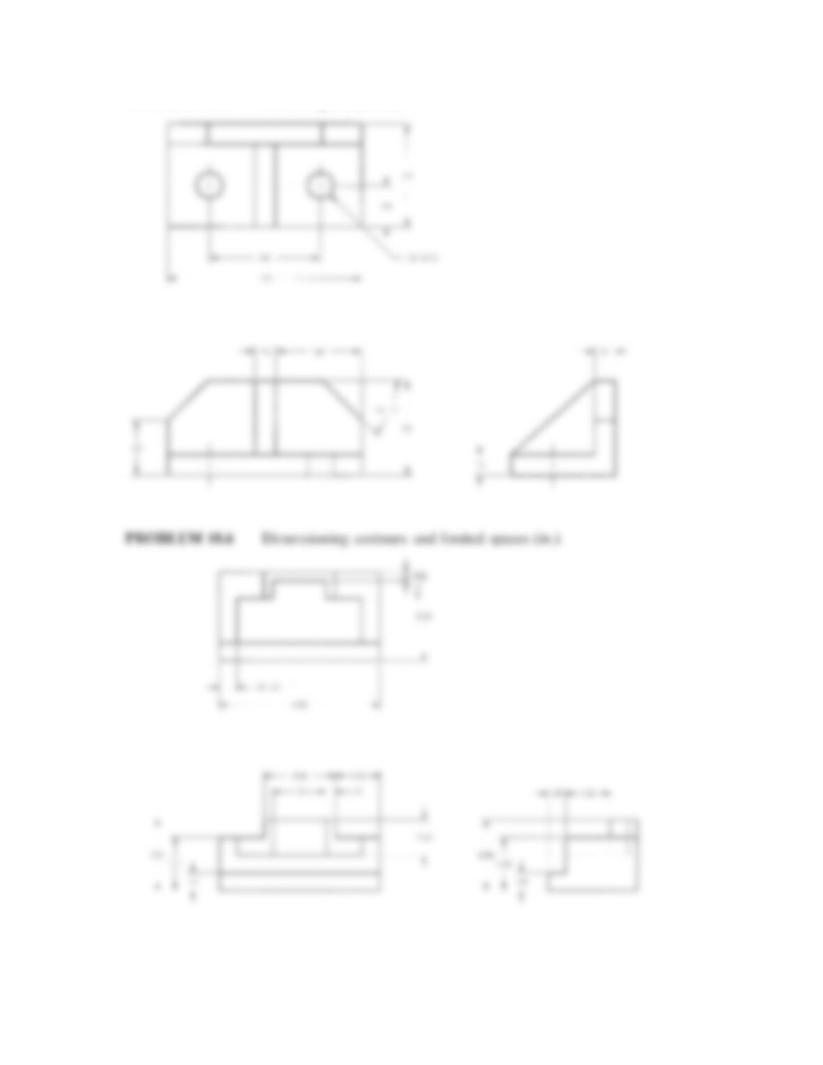
PROBLEM 10.6 Dimensioning contours and limited spaces (in.)
Part Name: Support
Material: Aluminum
.25 .25
1.25
2.00
4.50
.50
2.00
.75
.50
1.25
1.00
2.00
1.50
2.50
PROBLEM 10.7 Limited spaces (metric)
Part Name: Selector Slide Kicker
Material: Aluminum 1510
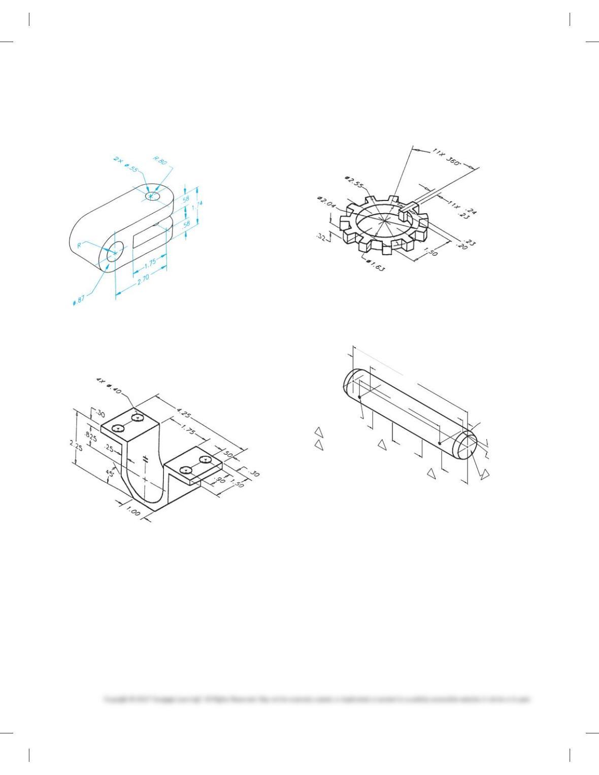
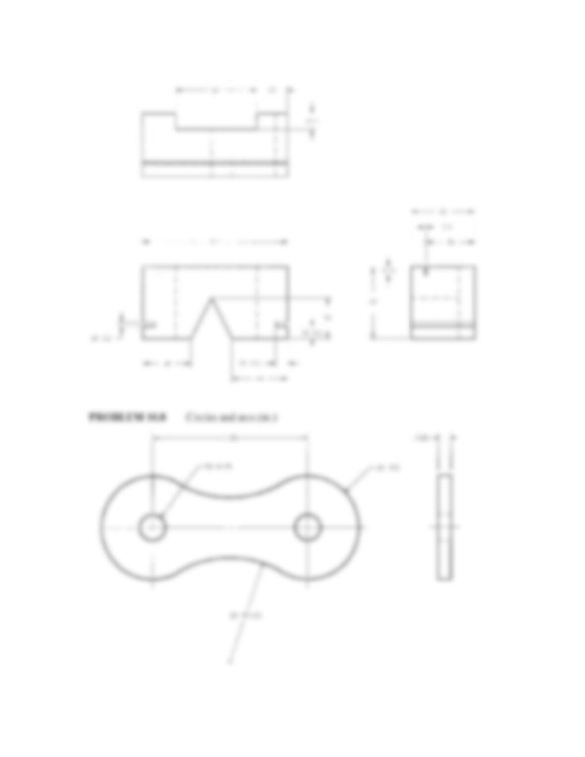
PROBLEM 10.8 Circles and arcs (in.)
Part Name: Chain Link
Material: SAE 4320
1.5
24
6.35
32
64
12.7
112
57 9.5
3.2
38
38
9.5
3.2
44
50
2X9.5
.125
1.50
2X R.5
2X Ø.25
R1.00
59728_ch10_EOC_ptg01.indd 6 03/02/16 10:26 am
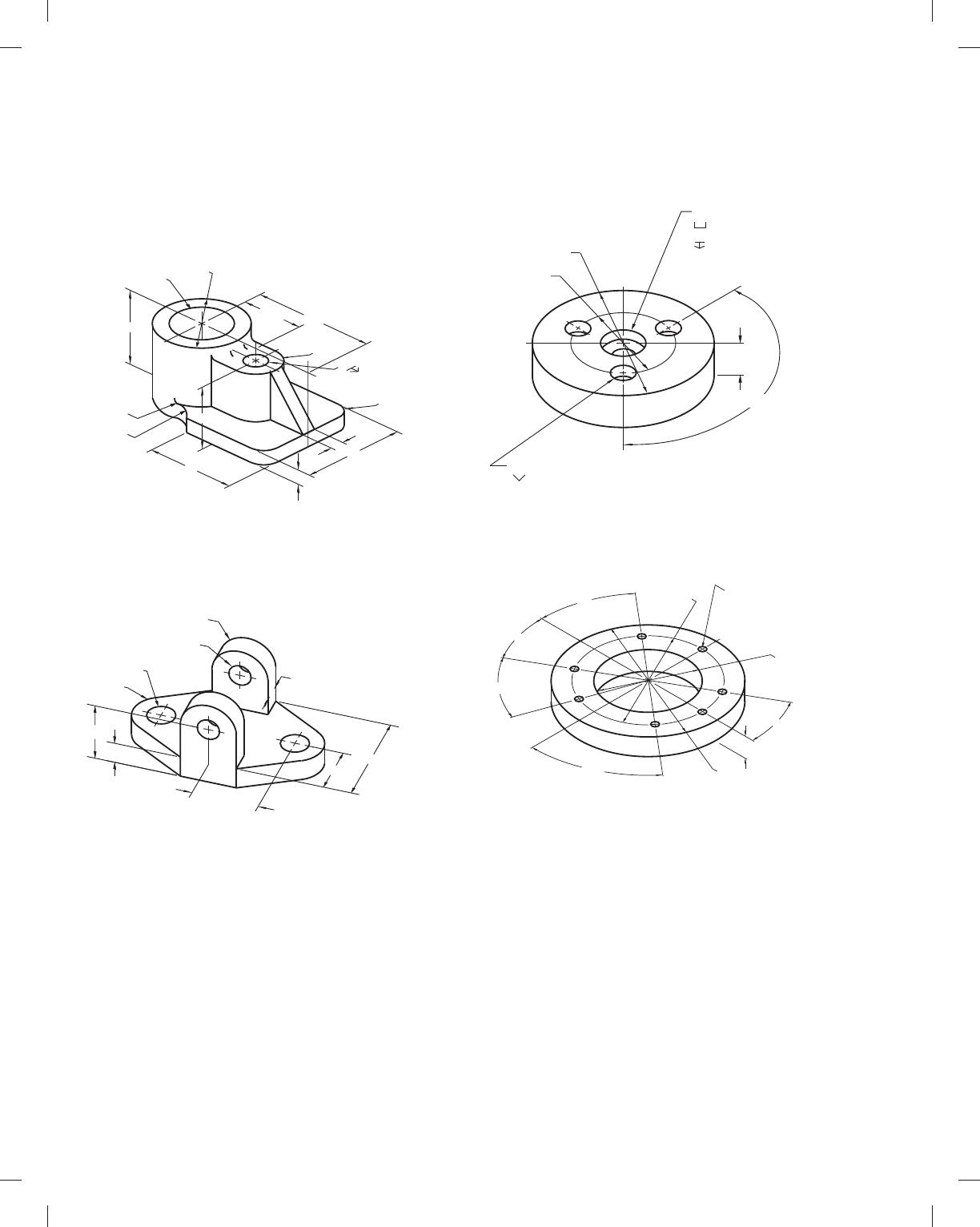
PROBLEM 10.10 Holes, angles, and arcs (in.)
Part Name: Journal Bracket
Material: Cast iron (CI)
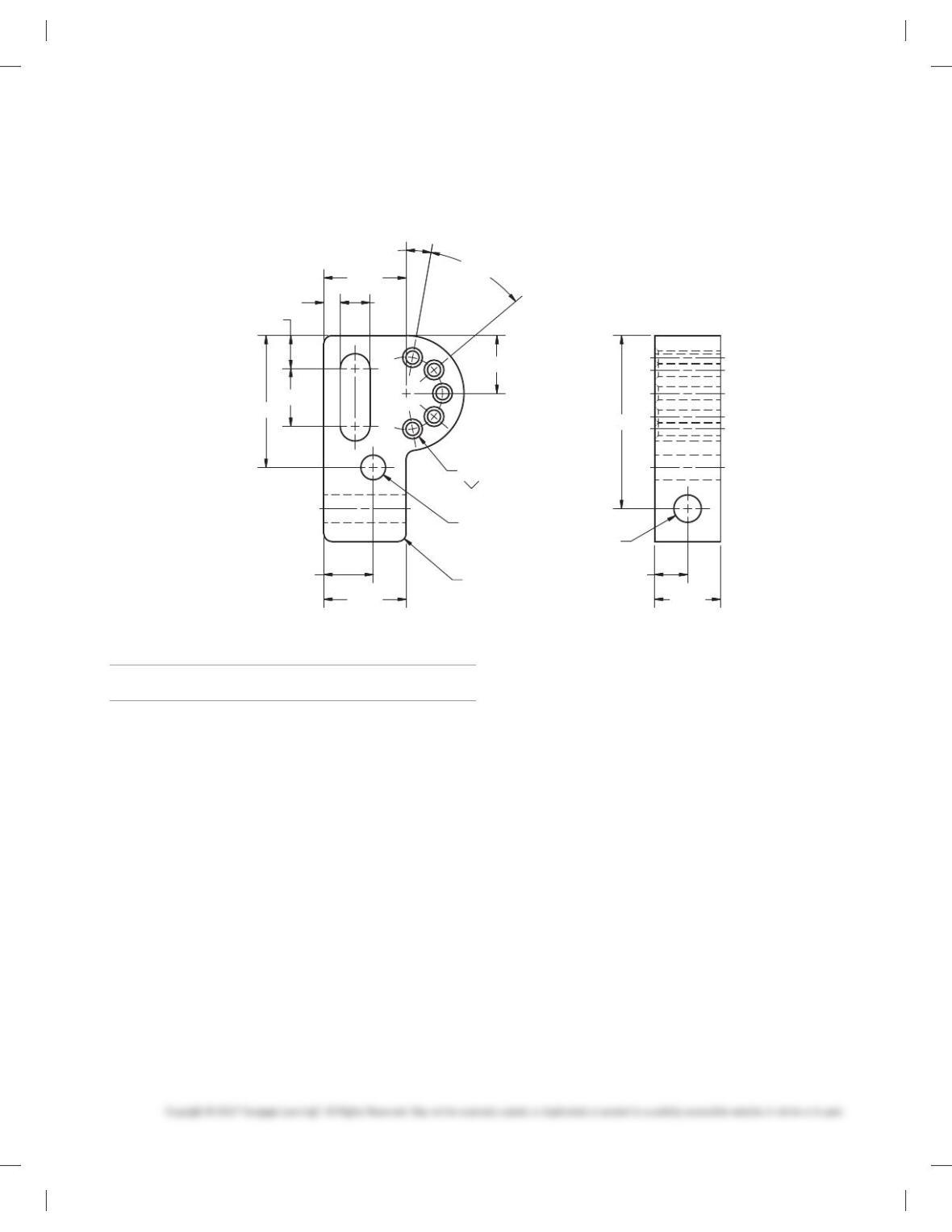
PROBLEM 10.9 Holes and limited space (in.)
Part Name: Pivot Bracket
Material: SAE 1040
PROBLEM 10.11 Dimensioning multiple features (in.)
Part Name: Lock Ring
Material: SAE 1020
PROBLEM 10.12 Single view (in.)
Part Name: Idler Gear Shaft
Material: MIL-S-7720
2X Ø.141 THRU 1.59
1.5000
Ø1.4985
44
3
2X15°
2X.9065
3MARK WITH 1196975
SURFACE FINISH 63 IN
mIN AREA INDICATED
4
8.00
1.38
2.06
6.187
1.38
.30
59728_ch10_EOC_ptg01.indd 7 03/02/16 10:26 am
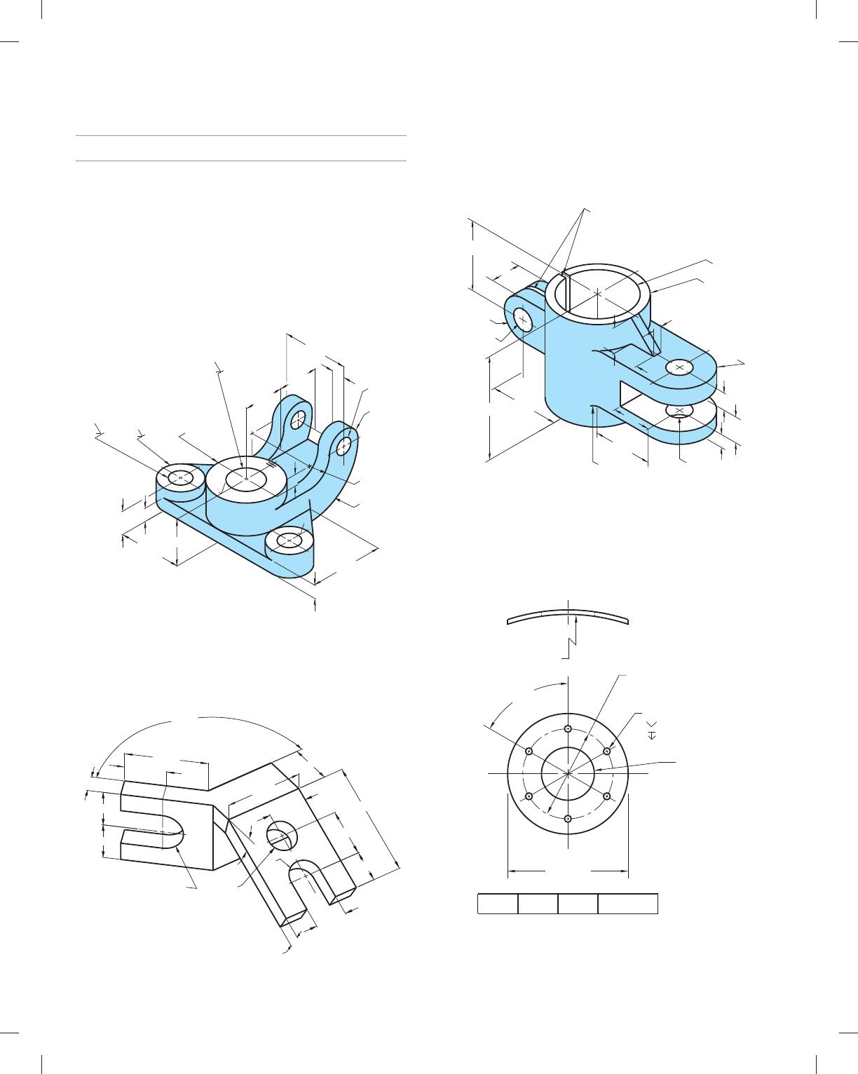
PROBLEM 10.13 Circles and arcs (metric)
Part Name: Bearing Support
Material: SAE 1040
Fillets: R6
2X Ø12
R15
2X12
2X Ø15
R15
2X38
64
32
35
12.5
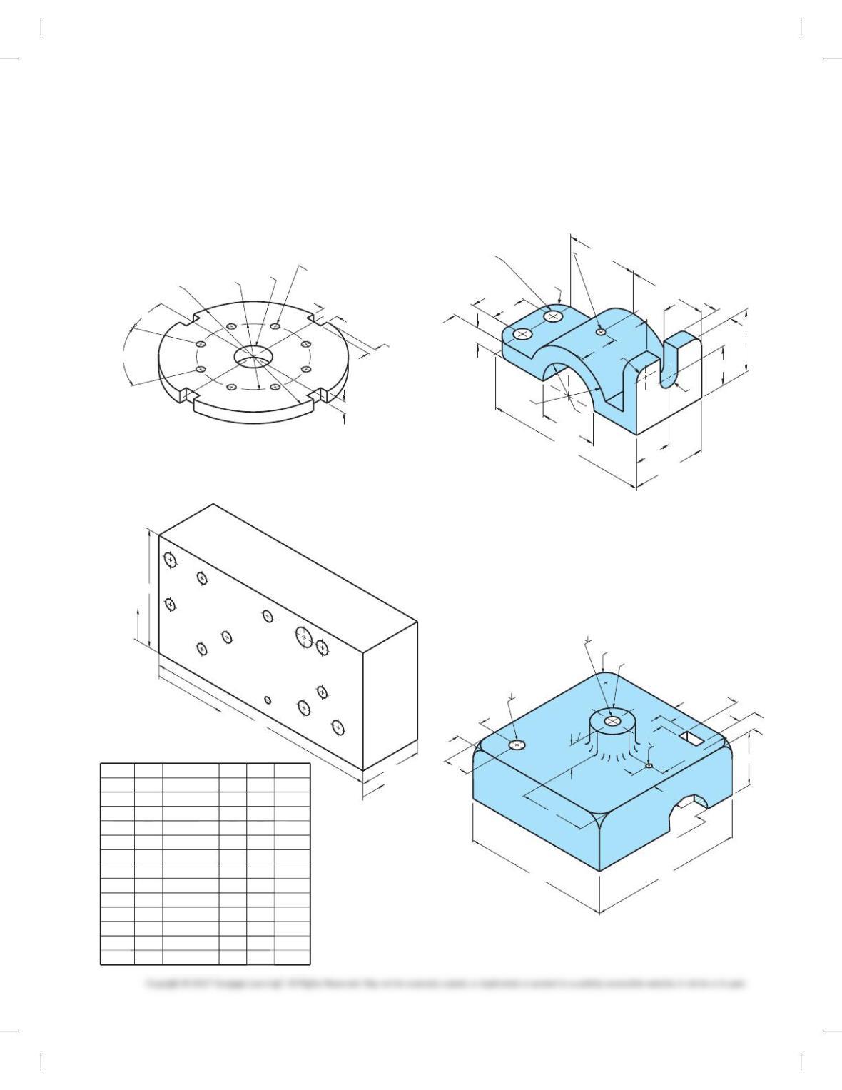
PROBLEM 10.14 Circles and arcs (metric)
Part Name: Hinge
Bracket Material: Cast aluminum
7X Ø.250
Ø5.375
50°
.75
30°
40°
30°
40°
Ø4.25 Ø3.00
PROBLEM 10.15 Machine features (in.)
Part Name: Spacer
Material: SAE 1030
PROBLEM 10.16 Polar coordinate dimensioning (in.)
Part Name: Spacer
Material: Plastic
57
BOTTOM
11
44.450
Ø44.400 (h8)
TANGENT
R22
48
Ø17.5
25
R12.7
86
9.53
Ø66.75
73
100
R19
50.8
Ø.50X82°
3X Ø.25 THRU
Ø.375
.870
.880
.214
.224
.75
Ø2.00
3X120°
Ø4.00
Ø
59728_ch10_EOC_ptg01.indd 8 03/02/16 10:26 am
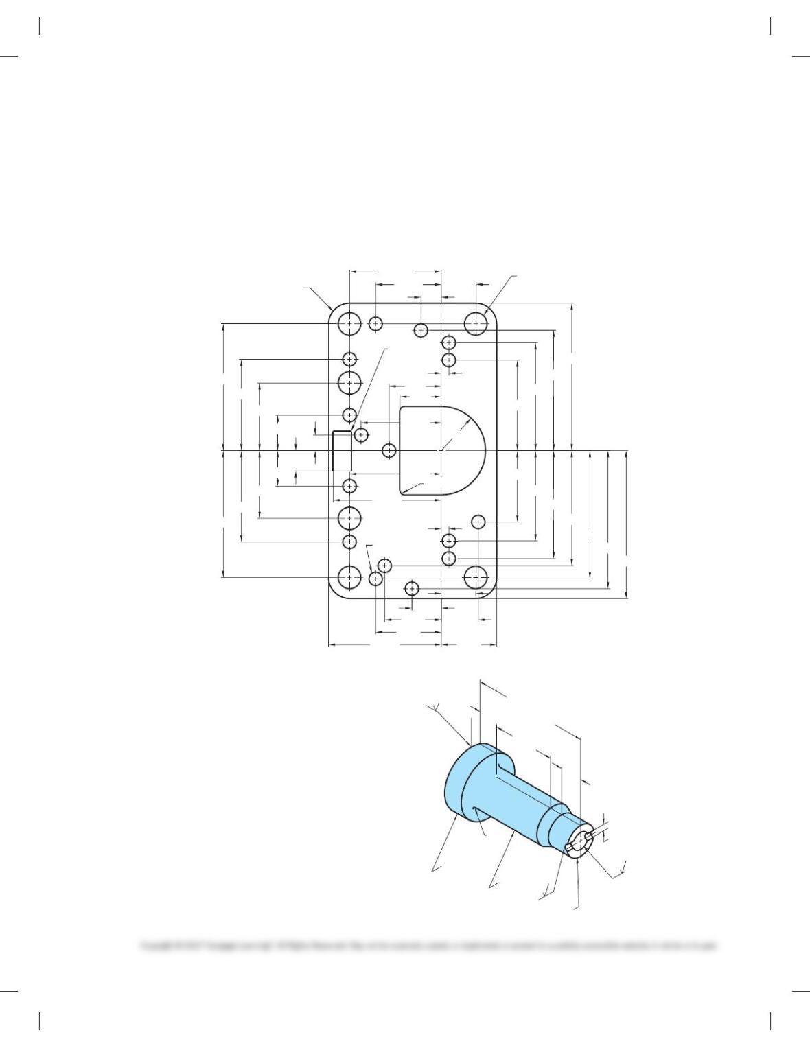
B1 C1
C3 C4
C6
C2
A1
B2
D1
B3
C5
B4
X
Y
Z
HOLE QTY.
1
1
1
1
1
1
1
1
1
1
1
1
DESCRIP.
Ø7
Ø2.5
X
64
5
72
64
79
19
48
5
30
72
19
48
Y
38
38
38
11
11
38
38
21
21
21
11
6
Z
18
THRU
THRU
THRU
THRU
THRU
THRU
THRU
THRU
THRU
THRU
THRU
A1
B1
B2
B3
B4
C1
C2
C3
C4
C5
C6
D1
Ø5
Ø5
Ø5
Ø5
Ø4
Ø4
Ø4
Ø4
Ø4
Ø4
90
45
24
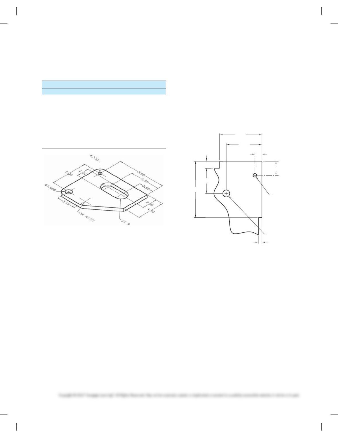
PROBLEM 10.17 Repetitive features (in.)
Part Name: Slot Plate
Material: Aluminum
SPECIFIC INSTRUCTIONS: Using the RC4 standard tolerance
limits found in Figure 10.81, the Appendices, or the Machinery ’s
Handbook, calculate and apply limits values to the 1.00
dimension.
Ø1.00
8X Ø.250
8X45°
22.5°
Ø5.00
Ø3.00
4X.500
.375
.250
PROBLEM 10.18 Tabular dimensioning (metric)
Part Name: Mounting Base
Material: Stainless steel
PROBLEM 10.19 Dimensioning circles, arcs, and slots(in.)
Part Name: Top Pipe Support Bracket
Material: SAE 1020
Fillets: R12
2X R.5
R
Ø.20 THRU
2X Ø.40
.90
.40
1.60
1.50
R.25
R
2.00
R1.15
.95
4.35
1.85
.40
.50
1.00
.95
1.90
.50
Ø4.5
Ø31
Ø11
12X R12
60
13.2
TYPICAL WALL
THICKNESS
19.4
21
121
21
16.8
13.2
63.5 13.2
44.45
Ø11
8
19.5
127
PROBLEM 10.20 Chain dimensioning (metric)
Part Name: Control Housing Cover
Material: Cast iron
Do not draw a sectional view. Sections are covered in Chapter 12.
Consider a bottom view to show wall thickness.
59728_ch10_EOC_ptg01.indd 9 03/02/16 10:26 am
ADVANCED PROBLEMS
Part 2: Problems 10.21 Through 10.35
PROBLEM 10.21
Dimensioning compound circles and arcs (in.)
Part Name: Multiple Shaft Support
Material: SAE 1030
Fillets and Rounds: R.08
SPECIFIC INSTRUCTIONS: Using the RC4 standard tolerance
limits found in Table 10.1 on page 316, Appendices, or the Ma-
chinery’s Handbook, calculate and apply limits values to the
following dimensions:
23 [.38
23 [1.125
[1.875
2X Ø.38
3.75
2X Ø2.25
2X Ø1.125 THRU
Ø1.875 THRU
Ø3.75
63
63
.75
R3.19
R1.33
2.25 2.25
1.320
3.562
.75
4.12
2.25 .94
R.94
.75
PROBLEM 10.22 Dimensioning auxiliary views (in.)
Part Name: Connector
Material: SAE 4320
Note: Finish all over 63 min.
R1.00
R
Ø1.50
1358
1.00
2.00
4.00
1.00
2.00
2.00
2.00
4.00
2.00
5.52
2.25
1.635
1.50
30
8
PROBLEM 10.23 Dimensioning small spaces (in.)
Part Name: Guide Bracket
Material: SAE 4020
Fillets and Rounds: R.125
2X R.875
Ø2.50
Ø2.00
2 WEBS
Ø.625
DRILL THRU
.125 SAW CUT
.375
.75
.50
Ø.625
R.625
.875
ON CENTER
2.00
3.00
.25
1.50
.75
.75
.75
R.125
1.50
PROBLEM 10.24 Chart drawing (in.)
Part Name: Tank Bracket
Material: 11 GA A570-30
Problem based on original art courtesy TEMCO.
1.574 1.448 1.322 DDIA
6X Ø.172
ØD
Ø3.015
6X 60
8
R4.937
92
8
Ø2.25
.055
59728_ch10_EOC_ptg01.indd 10 03/02/16 10:26 am
PROBLEM 10.25 Arrowless dimensioning (in.)
Part Name: Metering Box Gasket
Material: Neoprene
Note: Dimensions have been corrected to allow for steel rule
blade.
PROBLEM 10.26 Casting drawing (metric)
Part Name: Slider
Material: ASTM 60 CI
Hardness: Brinell 180-220
SPECIFIC INSTRUCTIONS: Draw part as finished. Include all
machining and casting dimensions on one detail drawing. The
patternmaker will apply unspecified allowances during
production.
SPECIFIC INSTRUCTIONS: Convert the engineering sketch to
arrowless tabular dimensioning. Set up a table that identifies
hole diameters, arc radii, and location dimensions from X and Y
coordinates. Dimensions above Y are 1 dimensions and below Y
are 2 dimensions. Dimensions to the right of X are 1 dimen-
sions and to the left of X are 2 dimensions.
Problem based on original art courtesy Vellumoid Inc.
.475 6X Ø.312
16X Ø.187
4X R.005
MAX
4X R.29
2X R.06
2.035
1.660
1.490
2.040
1.905
1.770
1.590
1.490
1.245
1.750
1.260
.935
.490
.276
.985
1.494
1.240
1.555
.905
.780
.405
.510
.765
.475
.105
.935
Y
1.260
1.750
1.105
.720
.570
1.265
.905
X
.280
.490
.215
1.250
.105
R.610
10.4
15.62
15.88
69.75
17.7
17.9
109.30 0.13
1.6
R2
Ø31.75
R
1.6
14.09 0
-0.25
TAPERED HOLE
25.4
25.3
0.8
00
-0.25
TO Ø10.16
AT OTHER END
Ø
Ø50
59728_ch10_EOC_ptg01.indd 11 03/02/16 10:26 am
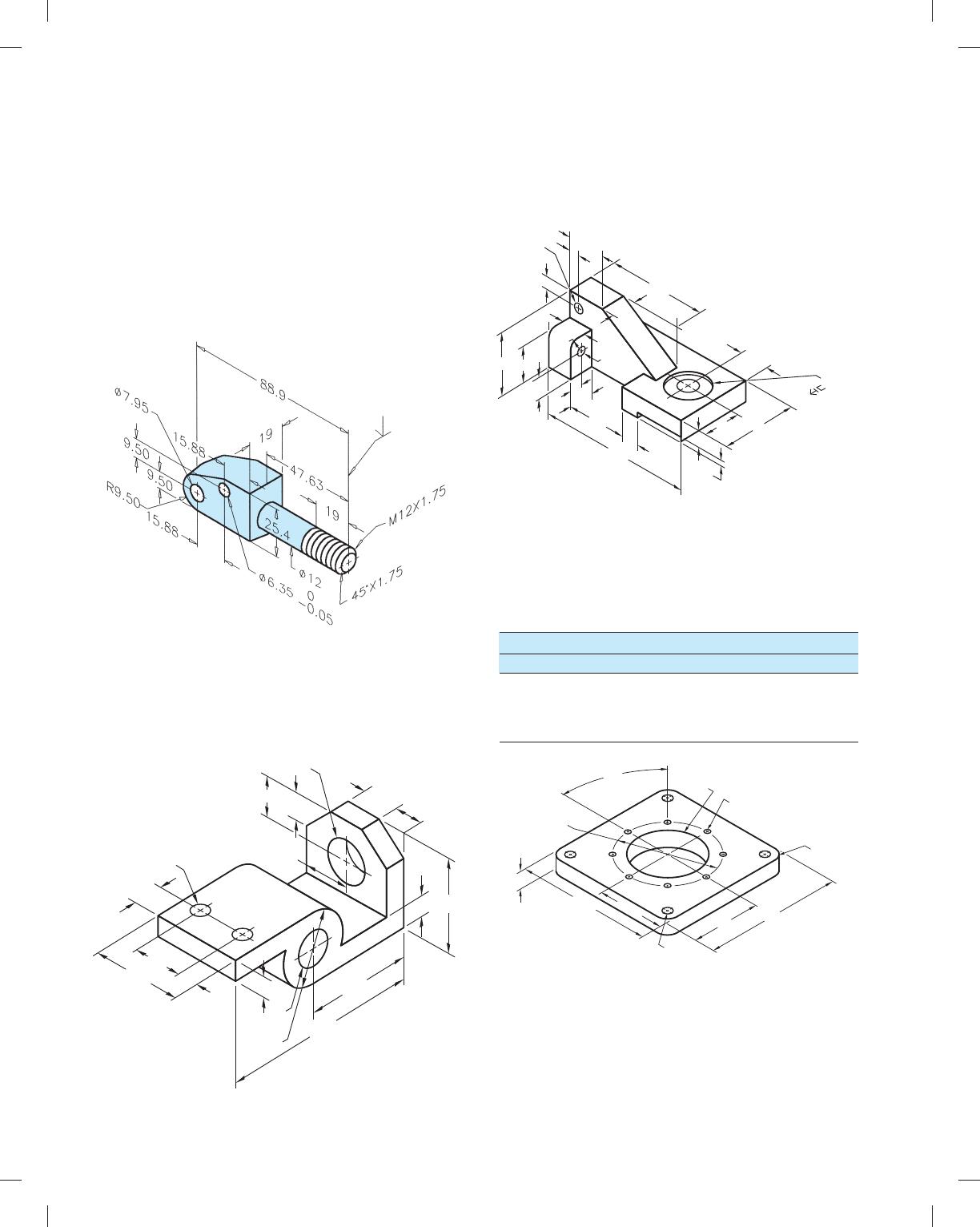
PROBLEM 10.27 Forging and machining drawings (metric)
Part Name: Pump Pivot Support
Material: HRMS (Hot rolled mild steel)
SPECIFIC INSTRUCTIONS: Prepare two drawings: one showing
only forging-related views, dimensions, and notes; and the other
showing only machining-related views, dimensions, and notes. Pro-
vide the draft angles recommended for steel (refer to chapter).
Add 3 mm to forging where finish surface is identified. Do not
draw thread symbol or thread note (M12 3 1.75).
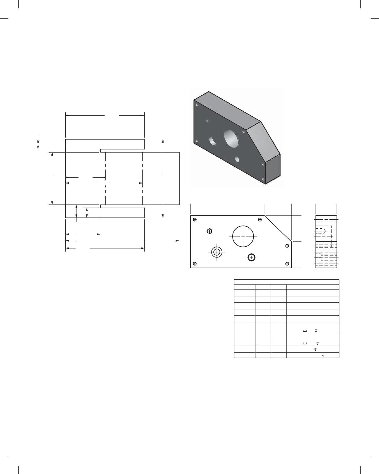
PROBLEM 10.28 Angles, holes, and arcs (in.)
Part Name: Mounting Bracket
Material: SAE 1020
Fillets: R.13
2X
[
.625 THRU
1.05
1.75
1.25 1.00
.75
.75
[
1
.52
1.50
1.00
1.825
3.50
[
1.25
THRU
[
2.50
3.88
.75
7. 1 3
3.25
PROBLEM 10.29 Contours, machine features, and limited
space (in.)
Part Name: Support Base
Material: SAE 1040
.31
.38
.50
.125
1. 1 3
Ø .28
THRU
2.88
.75
.75
1.75
4.83
.50
1.25
.88
2.25
[
.525
[
1. 125
.063
1.876
1.06
.63
R.25
.75
[
.250
THRU
.38
PROBLEM 10.30 CAD/CAM (in.)
Part Name: Spacer
Material: SAE 1030
8X 45
8
Ø4.50
6.00
3.00
4X Ø.375
3.00
6.00
4X R.50
Ø4.00 8X Ø.250
.75
Tool Type Tool No.
JOB PLAN
Diameter CAD Layer
Drill
Drill
End Mill
1
2
3
1
2
3
.250
.375
.500
59728_ch10_EOC_ptg01.indd 12 03/02/16 10:26 am
PROBLEM 10.31 CAD/CAM (in.)
Part Name: Cover Plate
Material: .500-thick aluminum
PROBLEM 10.32 Make a photocopy of the drawing below
and then sketch a drill jig on the drawing to satisfy the follow-
ing TDR. You can also redraw the drawing using manual draft-
ing or CADD and then draw the drill jig, if preferred by your
course objectives:
PART NAME:———————PART
PART NO:————————-XXXX-XX
OPERATION:———————DRILL .500 DIA HOLE
MACHINE:————————USE HAND DRILL
FIXTURE:————————- PICKOFF JIG LOCATING THE
HOLE 1.800 AND 2.530 FROM
THE EDGES OF THE PLATE
Tool Type Tool No.
JOB PLAN
Diameter CAD Layer
End Mill
End Mill
End Mill
1
2
3
1
2
3
.750
.500
.250
Spot Drill 4
5
4
5
.125
.500Drill
Drill
Clamps
66
7
1.000
Length
1.000
1.000
1.000
1.000
1.000
1.000
Ø.50 THRU
1.80
.50
2.53
.50
3.00
Ø.25 THRU
1.00
.25
4.00
59728_ch10_EOC_ptg01.indd 13 03/02/16 10:26 am
PROBLEM 10.33 Correct ASME errors (in.)
Part Name: Electronics Divider
Material: .125 in. Thick, Acrylonitrile-butadiene-styrene (ABS)
The given drawing has intentional ASME dimensioning errors.
Redraw the part using correct ASME dimensioning standards as
described throughout Chapter 10.
PROBLEM 10.34 Tabular dimensioning (metric)
Part Name: Mounting Plate
Material: 7075 Aluminum
A1 A2
A3
A4 A5
B1
C1
D1
E1
0
70
96
0
50
25
0
20
HOLE TABLE
HOLE XDIM YDIM DESCRIPTION
A1 4.00 4.00 Ø3 THRU
A2 92.00 4.00 Ø3 THRU
A3 92.00 21.00 Ø3 THRU
A4 4.00 46.00 Ø3 THRU
A5 66.00 46.00 Ø3 THRU
B1 58.00 10.00 Ø6 THRU
C1 25.00 15.00 Ø6 THRU
D1 50.00 30.00
E1 18.00 35.00
Ø7 5
M5X0.8-6H 6
Ø20 15
Ø10 5
.380
2.000 3.000
1.321
1.516
3.000
4.323
.500
.380
3.000
2.927
59728_ch10_EOC_ptg01.indd 14 03/02/16 10:26 am
Ø.375
.450
.875
.500
.250
2.000
1.250
.875
.750
1.250
4X40°
10°
5X Ø.200 THRU
Ø.300X82°
2.625
.500
R.1254X
1.000
Ø.417 THRU
PROBLEM 10.35 Rectangular and polar coordinate dimensioning (in.)
Part Name: Adjustable Hitch
Material: SAE 1085
MATH PROBLEMS
Part 3: Problems 10.36 Through 10.45
Find the distance between these points on a 2-D drawing:
PROBLEM 10.36 (5, 7) and (8, 9)
PROBLEM 10.37 (3, 24) and (7, 10)
PROBLEM 10.38 (22, 25) and (8, 3)
PROBLEM 10.39 (6, 4) and (6, 12)
Find the distance between these points on a 3-D drawing:
PROBLEM 10.40 (0, 0, 0) and (5, 7, 9)
PROBLEM 10.41 (1, 2, 3) and (12, 18, 20)
PROBLEM 10.42 (21, 0, 6) and (1, 3, 9)
PROBLEM 10.43 (6, 12, 3) and (22, 12, 8)
PROBLEM 10.44 What is the straight-line distance (to the
nearest 1/160) from one corner of a piece of 49 by 89 plywood to
the opposite corner?
PROBLEM 10.45 What is the straight-line distance (to the
nearest 1/40) from one corner at the floor of a room to the op-
posite corner at the ceiling if the dimensions of the room are
209 high by 309 wide by 509 long?
59728_ch10_EOC_ptg01.indd 15 03/02/16 10:26 am
102
Chapter 10
Dimensioning and Tolerancing
Solutions to End-of-Chapter Problems
Part 1: Problems 10.1 Through 10.20
PROBLEM 10.1 Basic practice (metric)
103
PROBLEM 10.3 Dimensioning basic practice (in.)
104
PROBLEM 10.5 Limited space (metric)
105
PROBLEM 10.7 Limited spaces (metric)