Chapter 10
10.1 a.
2
2
3
1
22
xy
xyxy
τ
σσσσ
σ
σ+
−
±
+
=
2
2
2
1
3
b. °=+
−
+
+
=22 ;2sin2cos
2
2
θθτθ
σσσσ
σ
xy
xyxy
n
xy
τ
10.2 a.
x
σ
= 2193 lb/ft
2
;
y
σ
= 3906 lb/ft
2
;
xy
τ
= 919 lb/ft
2
;
θ
= 168º
=
2
3458.16 lb / ft
82
© 2018 Cengage Learning®. All Rights Reserved. May not be scanned, copied or duplicated, or posted to a publicly accessible website, in whole or in part.
3906 2193 sin[(2)(168)] (919) cos[(2)(168)]
2
n
τ
−
= − = −
2
1187.91 lb / ft
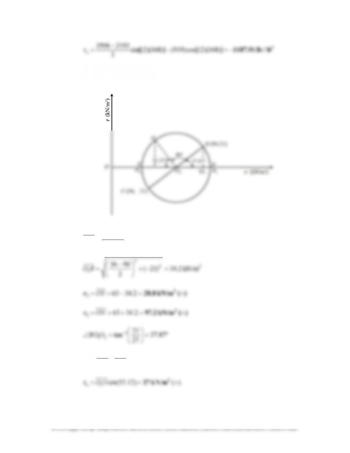
10.3 a. The Mohr’s circle is shown.
2
21
2
1
kN/m 276390 ;kN/m 63
2
3690 =−==
+
=OOOO
22
2
9036 =−+
−
27
21
b.
)( kN/m 42
2
+=−=−= )12.52cos(2.3463)12.52cos(
11
DOOOσ
n
2

83
10.4 a. The Mohr’s circle is shown.
90
21
b.
2
lb/ft 517.06=−=+−= )71.80cos(1.142540)3071.50cos(
11
DOOOσ
n
84
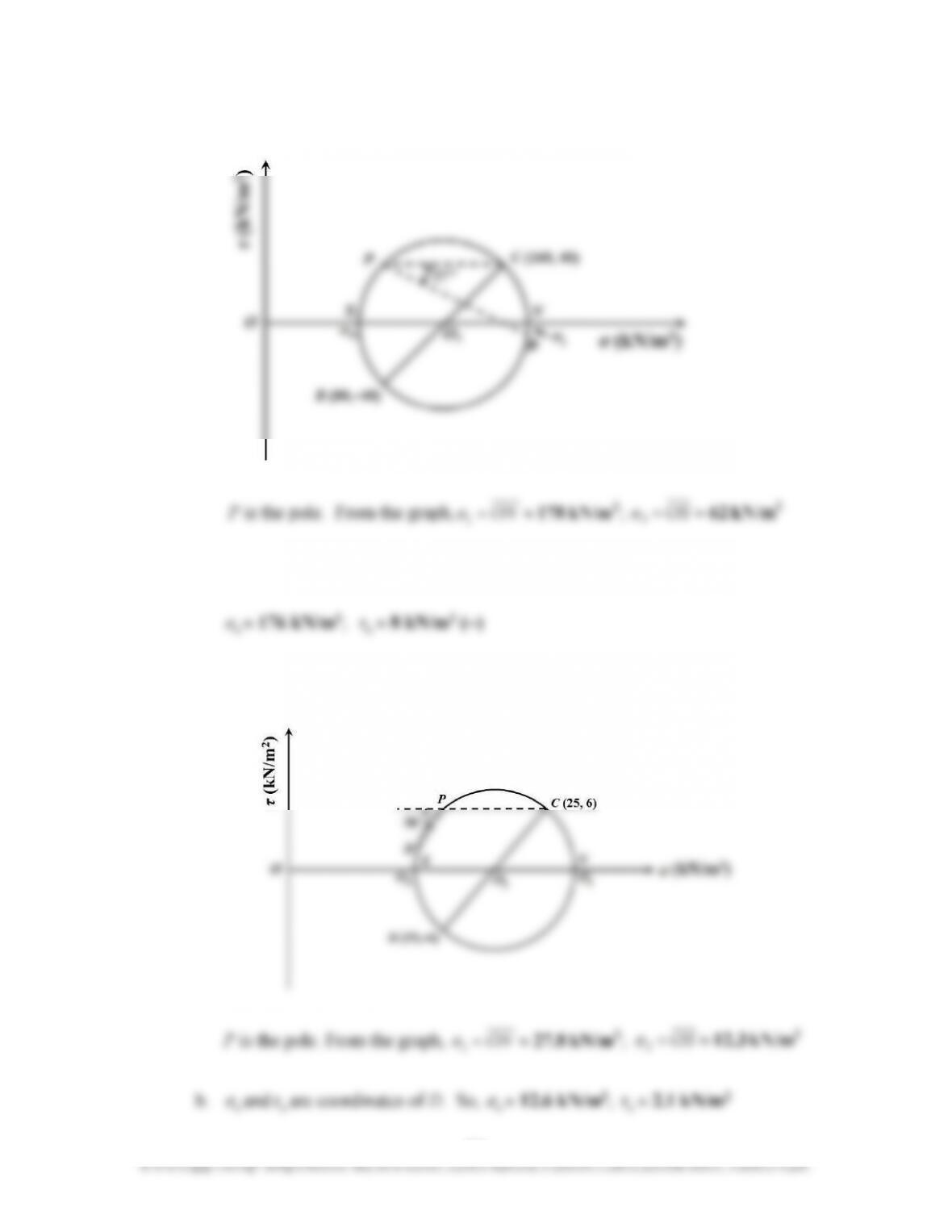
10.5 a. The Mohr’s circle is shown.
1
3
b.
n
σ
and
n
τ
are coordinates of
D
. So
n
n
10.6 a. The Mohr’s circle is shown.
n
n
n
n
10.7
P
86
© 2018 Cengage Learning®. All Rights Reserved. May not be scanned, copied or duplicated, or posted to a publicly accessible website, in whole or in part.
22
222
3
2
2
00215.0)( ;
])5()5.12[(
)5)(63(sin2
)(
q
q
zz
=∆
+
=∆
σ
π
σ
Horizontal component of
q
2
=
q
2
cos
63°
From Eq. (10.17):
2
222
2
2
222
2
2
3
002749.0
]55.12[
)5)(5.12)(63(cos2
)(
2
)(
q
q
zx
xzq
σ
z
=
+
=
+
=∆
ππ
Total vertical stress increase,
∆
z
σ
= 58 kN/m
2
= (∆
z
σ
)
1
+ (∆
z
σ
)
2
+ (∆
z
σ
)
3
58 = 11.94 + 0.00215
q
2
+ 0.002749
q
2
kN/m 9402
=
2
q
10.12
B
= 48 ft;
q
= 1450 lb/ft
2
;
x
= 28.8 ft;
z
= 21 ft
)21)(2(2
)8.28)(2(2 =
∆
z
x
z
σ
10.13 818.0 10.4, Table From.1
8
)4)(2(2
;0
8
)0)(2(2 =
∆
====
qB
z
B
x
z
σ
z
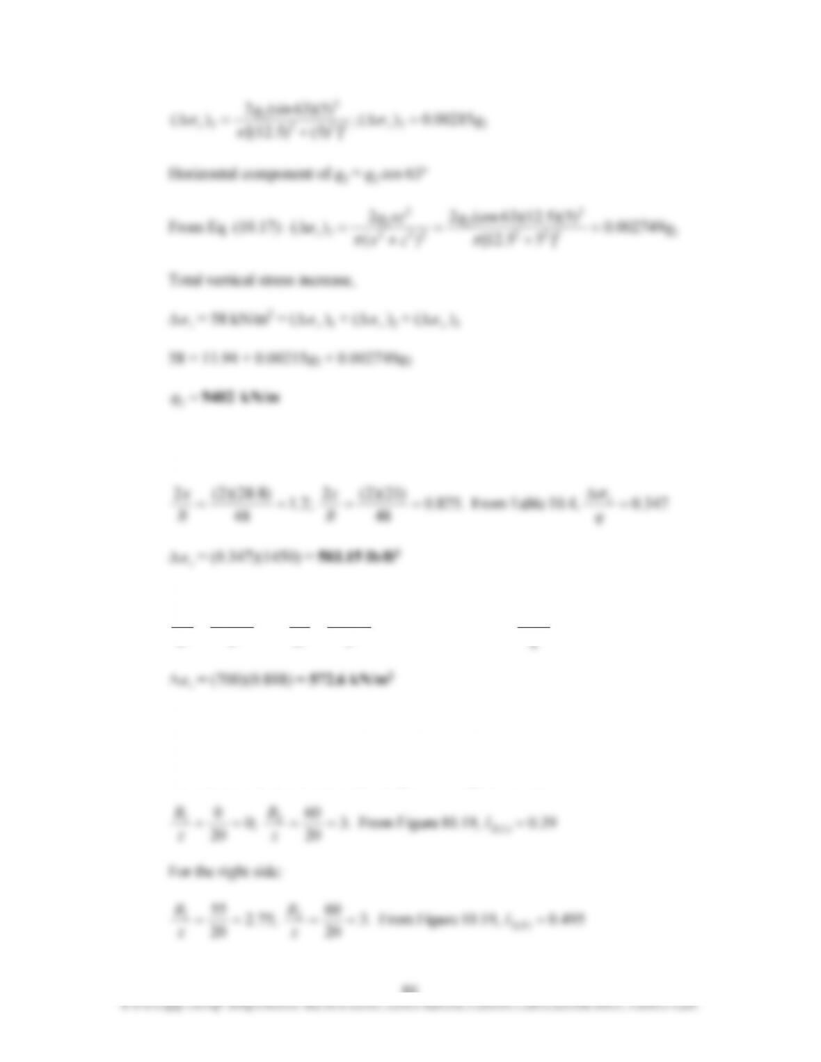
10.14 Refer to the figure on the following page.
For the left side (with the notations given in Figure 10.18):

87
© 2018 Cengage Learning®. All Rights Reserved. May not be scanned, copied or duplicated, or posted to a publicly accessible website, in whole or in part.
∆
z
σ
=
q
[
I
2(L)
+
I
2(R)
] = (3332)(0.39 + 0.495) = 2948.8 lb/ft
2
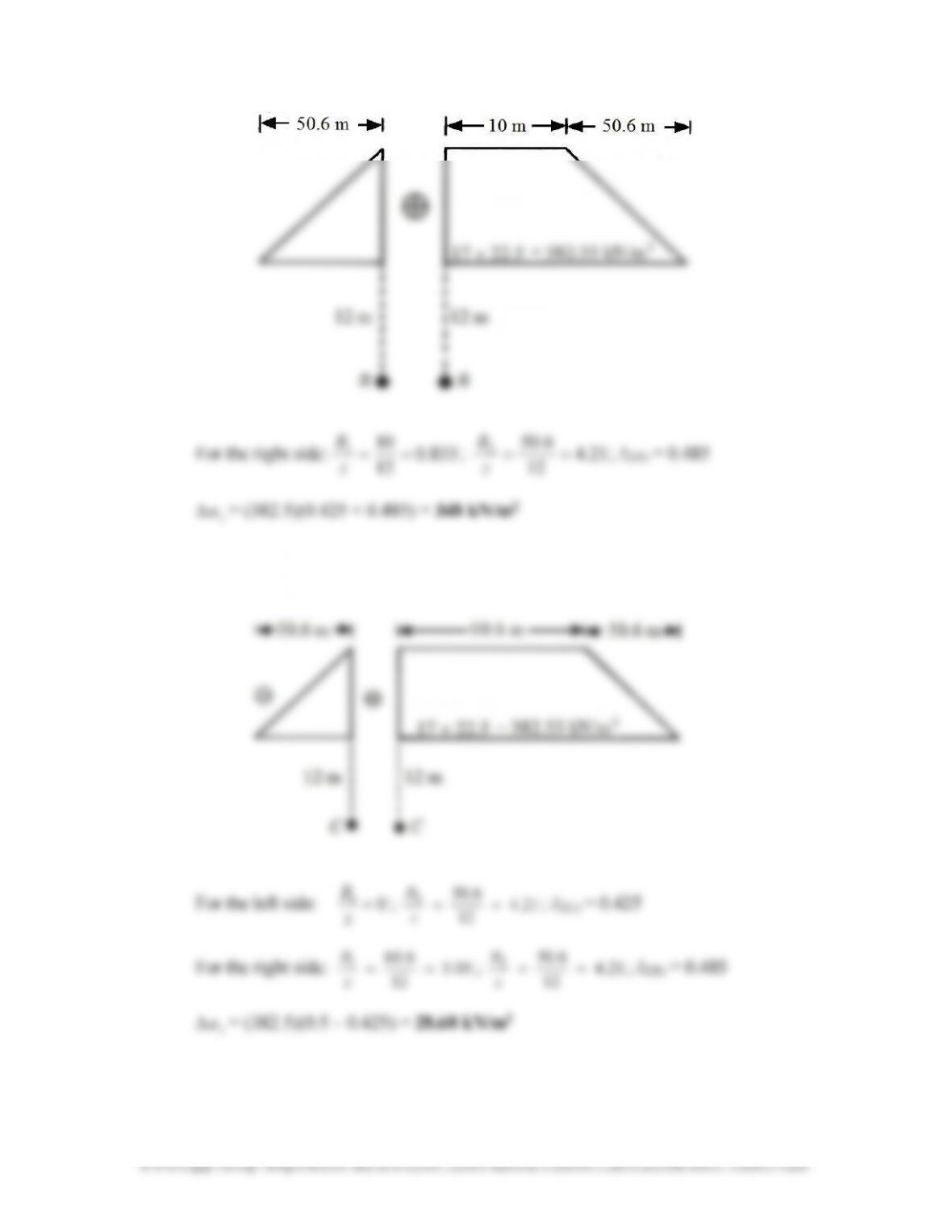
10.15 At
A
:
At
B
:
12
z
12
z
88
© 2018 Cengage Learning®. All Rights Reserved. May not be scanned, copied or duplicated, or posted to a publicly accessible website, in whole or in part.
For the right side:
833.0
12
10
1
==
z
B
;
21.4
12
6.50
2
==
z
B
;
I
2(R)
= 0.485
∆
z
σ
= (382.5)(0.425 + 0.485) = 348 kN/m
2
At
C
:
z
89
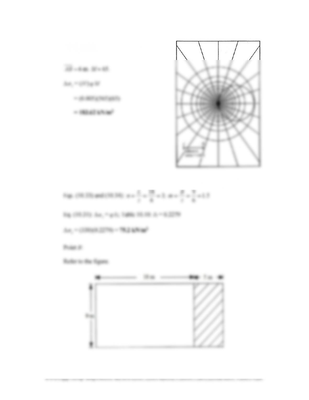
10.16 Refer to Newmark’s chart.
The plan is drawn to scale.
10.17 Point
A
:
9
18 ======
B
L
90
×
−
×
=∆ m9m5area
todue at B stress
m9m23area
todue at B stress
z
σ
z
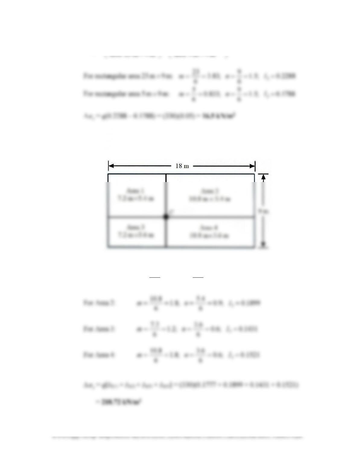
Point
C
:
Refer to the figure.
For Area 1:
0.1777 ;9.0
6
4.5
;2.1
6
2.7
3
===== Inm
10.18 Eqs. (10.36), (10.38), (10.39), and (10.40):
m 5.4
2
9
2
=== B
b
;
2
9
18
1
===
B
L
m
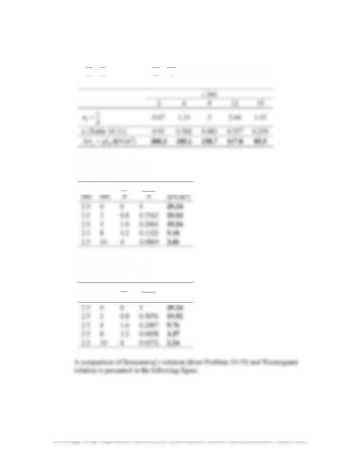
10.19 Eq. (10.27) and Table 10.7:
q
= (4)(9.81) = 39.24 kN/m
2
R
z
z
σ
z
∆
∆
z
σ
10.21 Eq. (10.28) and Tables 10.8 and 10.9:
q
= (5)(9.81) = 49.05 kN/m
2
z
(m)
r
(m)
R
(m)
R
z
R
r
A
′
B
′ ∆
z
σ
(kN/m
2
)
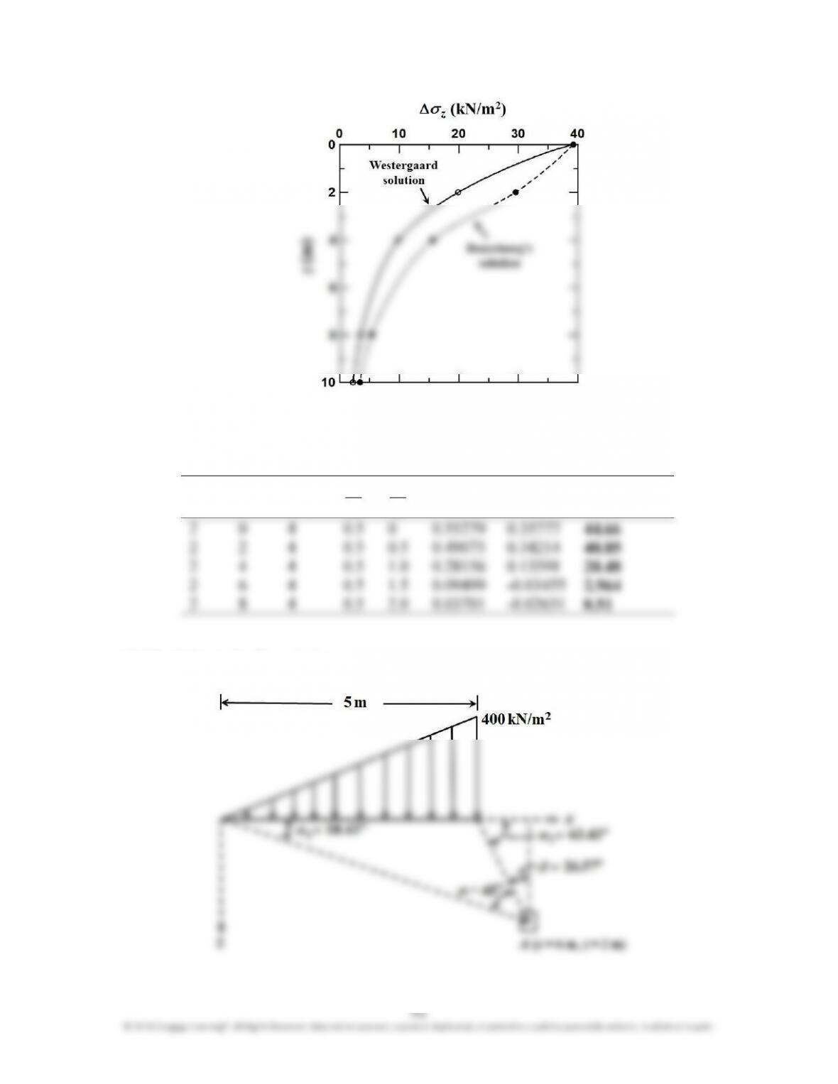
10.22 Refer to the figure below.
°=
=
−
43.18
6
2
tan
1
1
α
−
2
1
z
CRITICAL THINKING PROBLEMS
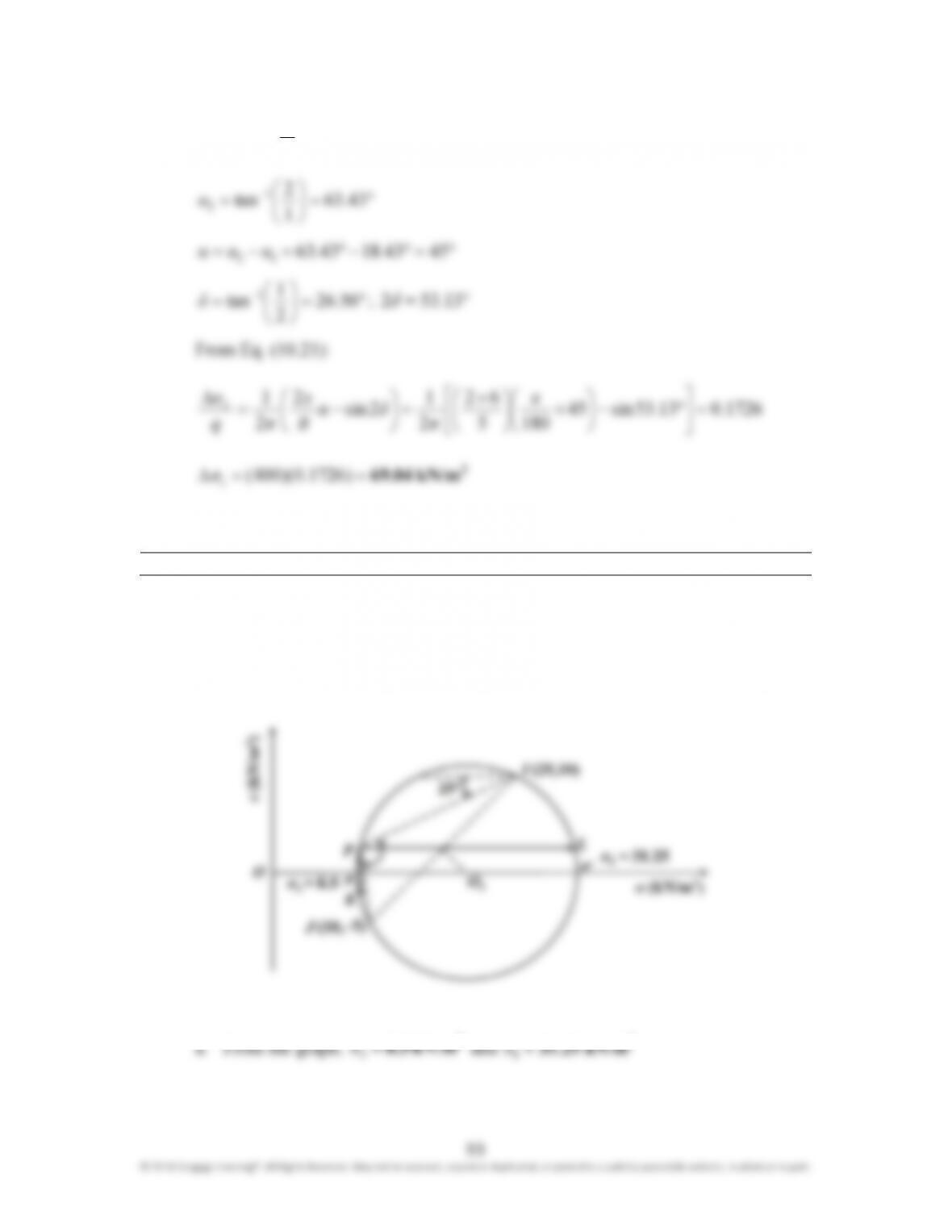
10.C.1 From the given stress conditions on planes
EB
and
FG
, the points
I
(25,10) and
J
(10,−5) are located, and the Mohr’s circle is drawn as shown below.
94
b. The pole
P
is located by drawing a line,
IP
, inclined at an angle 25° with the
c. By drawing horizontal and vertical lines from the pole
P
, the points
L
(31, 2.5)
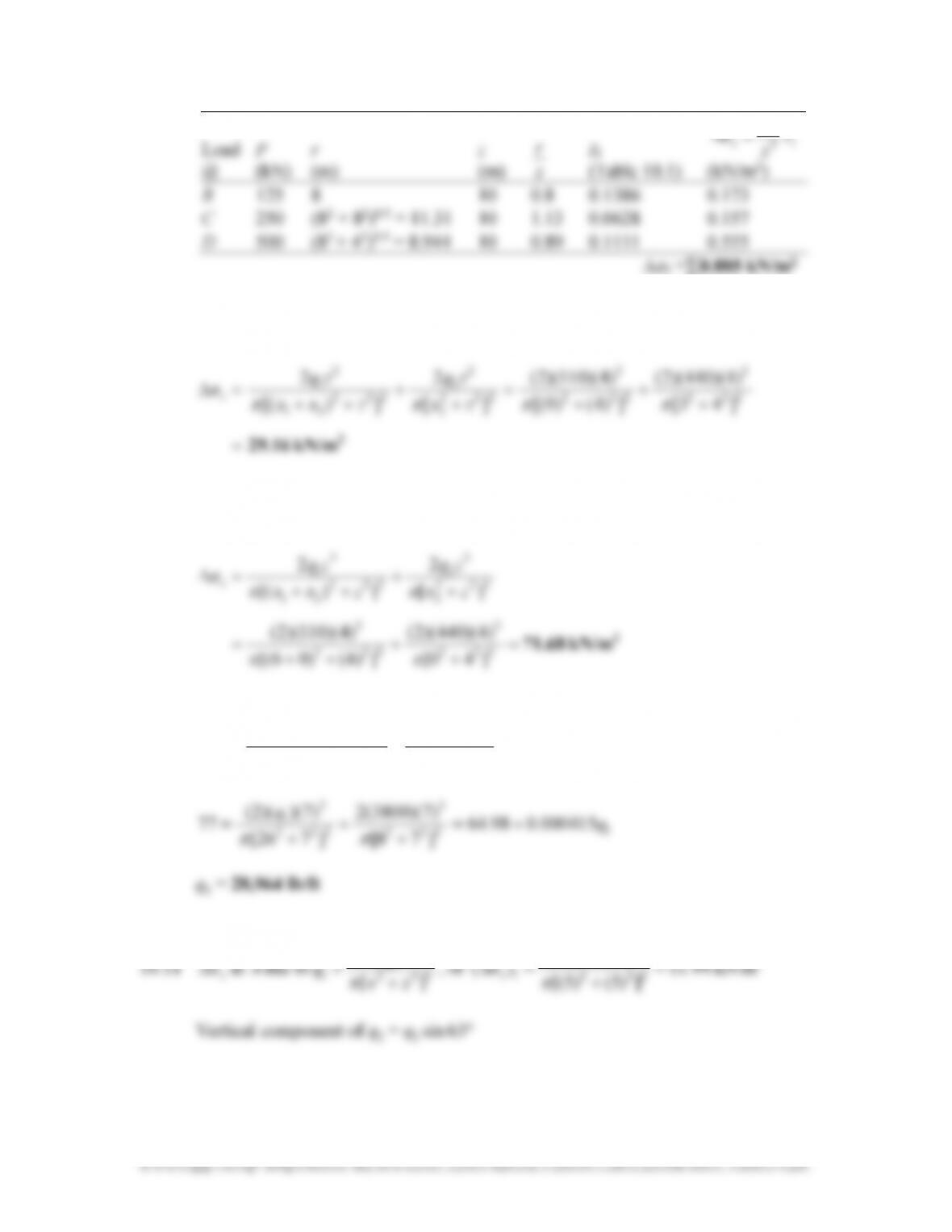
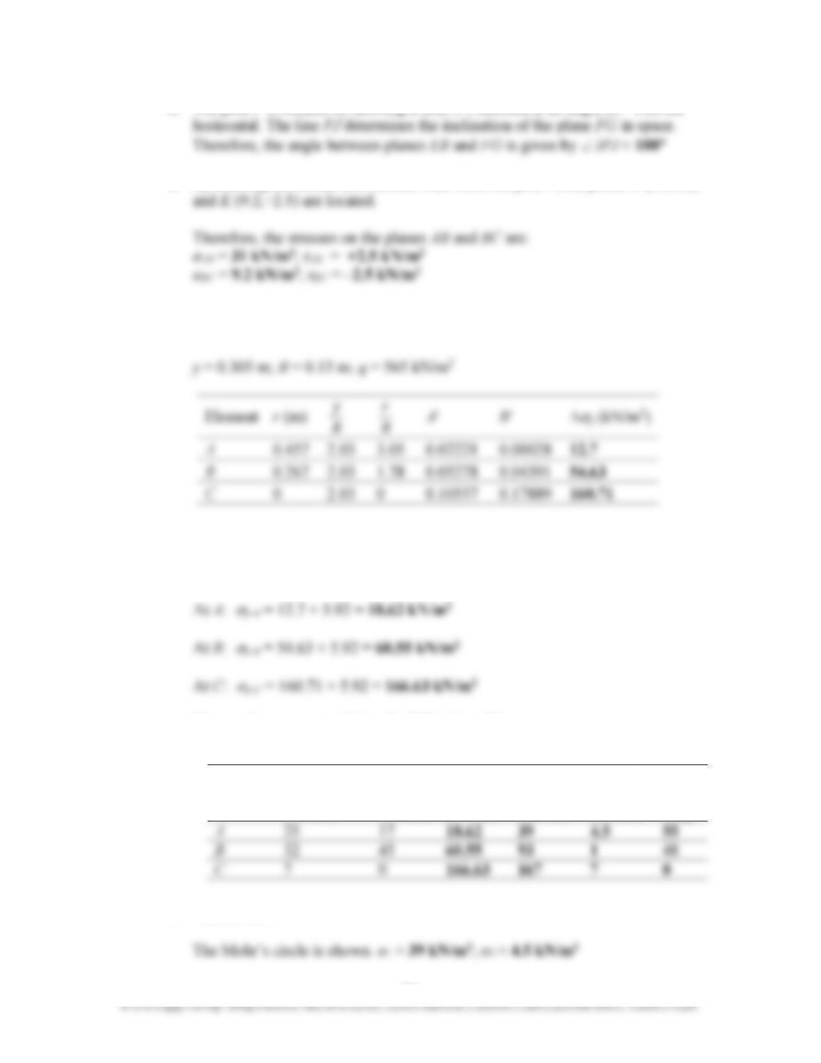
10.C.2 a. Vertical stress increase due to wheel load:
Overburden pressure at the middle of the layer = 0.305 × 19.4 = 5.92 kN/m
2
Total vertical pressure, ∆
σ
y
:
2
These values are entered into the following table.
Element
at
Horizontal
stress,
σ
x
(kN/m
2
)
Shear
stress,
τ
(kN/m
2
)
Vertical
stress,
σ
y
(kN/m
2
)
σ
1
(kN/m
2
)
σ
3
(kN/m
2
)
α
i
(deg)
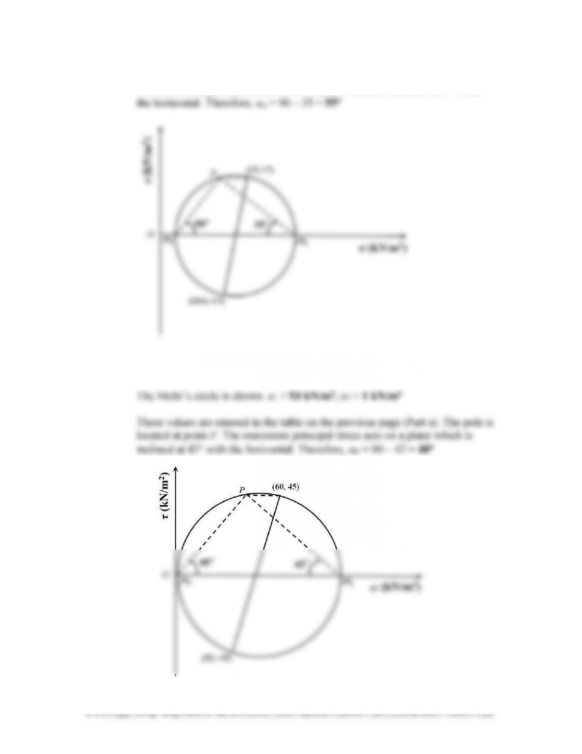
b. Element at
A
:
95
These values are entered in the above table. The pole is located at point
P
.
The maximum principal stress acts on a plane which is inclined at 35° with
Element at
B
:
2
2
96
Element at
C
:
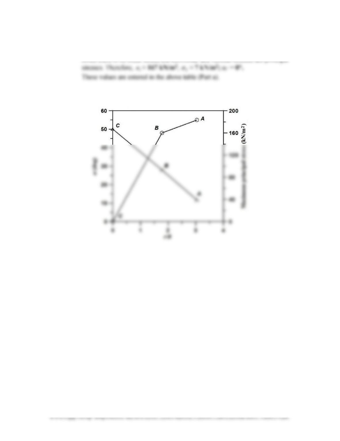
Since there is no shear stress, the horizontal and vertical stresses are principal
2
2
These values are entered in the above table (Part a).
c. The plot is shown below