( )
( )
2
2
2
2
2inlbm768.78
ft
in
12ftlbm547.0 =
=
P
I
t
803.1=
t
The drag coefficient is
2
20
DDD CCC +=
( )
( )
135.08.1sin200.4131.0 2=+=
D
C
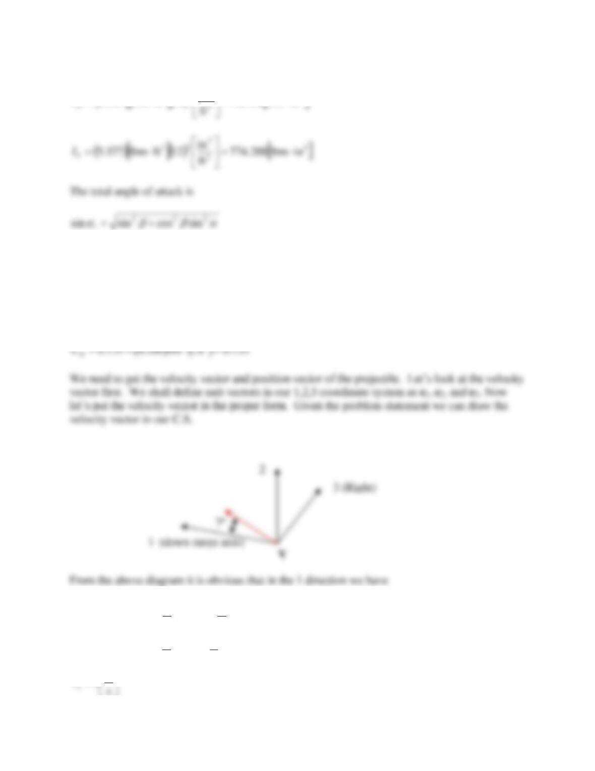
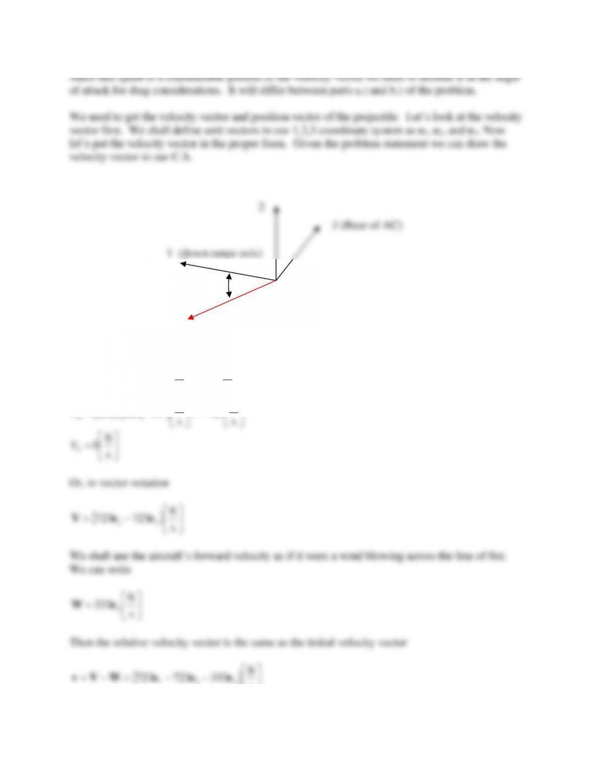
We need to get the velocity vector and position vector of the projectile. Let’s look at the velocity
vector first. We shall define unit vectors in our 1,2,3 coordinate system as e1, e2, and e3. Now
let’s put the velocity vector in the proper form. Given the problem statement we can draw the
velocity vector in our C.S.
From the above diagram it is obvious that in the 1 direction we have
( )
( )
=
=s
ft
015,1
s
ft
7cos022,1
1
V
( )
( )
=
=s
ft
125
s
ft
7sin022,1
2
V
=s
ft
0
3
V
1 (down range axis)
2
3 (Right)
V
7º
1==
( )
139.0000.8sin
2==
i
( )
026.0500.1sin
3==
i
1 (down range axis)
3 (Right)
1.500º
8.000º
( )
( ) ( )
( )
( )
−=
−−−= s
rad
2.0
s
rad
5.1sin35.1cos8sin2
0
i
( )
( )
=
=s
rad
981.1
s
rad
8cos2
0
j
( )
( ) ( )
( )
( )
−=
−+−= s
rad
006.3
s
rad
5.1cos35.1sin8sin2
0
k
( )
−+−=
−= s
rad
006.3981.12.0
s
rad
32 32100 eeekjωijk
vector di/dt is then given by
iω
i=
dt
d
−−=−−= s
rad
98.197.247.0
026.0139.0990.0
006.3981.12.0 321
321
eee
eee
i
dt
d
The angular momentum vector, h is then obtained through
+= dt
d
I
pI
T
pi
iih
The first term on the RHS is
( )
( )
( )
321
2
2
026.0139.0990.0
inlbm288.774
s
rad
932inlbm768.78
eeei ++
−
−
=
T
p
I
pI
2
3 (Right)
i
1.500º
1 (down range axis)
rad
p
pI
( ) ( )
( )
( ) ( )
( )
( )
−=
−
== s
1
019.0
ft
in
12lbm1.322
55.0
s
rad
932in134.4ft093.0
ft
lbm
0751.0
2
~
2
3
m
SdpC
Cp
p
N
N
( )
=
+
=s
ft
0
2
~
m
CCvSd
CNN
N
q
q
( )
( ) ( ) ( )
( )
( )
( )
−=
−
=
+
=s
1
687.0
in–lbm288.7742
7.8in134.4ft093.0
s
ft
022,1
ft
lbm
0751.0
2
~
2
2
2
2
3
2
T
MM
MI
CCvSd
Cq
q
( ) ( ) ( )
( )
( )( )
( )
=
== s–ft
rad
986.0
in–lbm288.7742
ft
in
12300.4in134.4ft093.0
s
ft
022,1
ft
lbm
0751.0
2
~
2
2
3
T
M
MI
vSdC
C
( ) ( )
( )
( ) ( )
( )
−=
−
== s–ft
rad
064.0
in–lbm288.7742
892.0
s
rad
932in134.4ft093.0
ft
lbm
0751.0
2
~
2
2
2
2
3
2
T
M
MI
pCSd
Cp
p
( ) ( ) ( )
( )
( ) ( )
( )
−=
−
== 22
2
2
2
3
2
s
rad
061.2
in–lbm288.7742
028.0
s
rad
932in134.4ft093.0
s
ft
022,1
ft
lbm
0751.0
2
~
T
l
lI
pCSdv
Cp
p
Now we have direct substitutions into the equations of motion to obtain the accelerations. Rather
than write each one out, I solved the vector equations using MathCAD. The equations are
( )
( )
Λgivvivv
V++++−=
p
NLD CCC
dt
d~~~
(8.320)
( )
( ) ( )
( )
iihhiivvivi
h−+−+++= qpP MMMll CCCCC
dt
d~~~~~
(8.321)
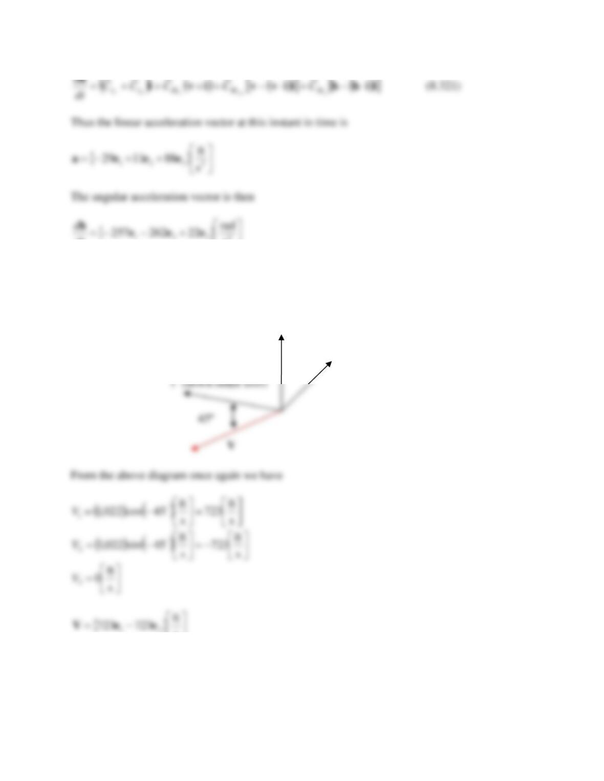
Thus the linear acceleration vector at this instant in time is
+−−= 2
321 s
ft
53019 eeea
The angular acceleration vector is then
+−= 2
321 s
rad
21271eee
h
dt
d
Problem 28 – A modified 105mm M1 projectile is fired downward from an aircraft moving at
200 knots at an angle of -45º from the horizontal with a muzzle velocity of 1,022 ft/s. The initial
pitch and yaw angles are 1.0º and 1.5º, respectively. The initial pitch and yaw rates are 3.5 rad/s
nose down and 2.5 rad/s nose left, respectively.
a.) If the projectile is fired off the right side of the aircraft and has the coefficients below at
this particular instant, write the acceleration vector and the angular momentum vector.
b.) Write the acceleration vector and the angular momentum vector assuming everything is
the same except now the projectile is fired off the left side of the aircraft.
c.) Comment on the differences between parts a.) and b.)
Please ignore the Coriolis acceleration and assume the weapon has a right hand twist.
Projectile Information
55.0
65.1
30.4
20.4
131.0
2
−=
=
=
=
=
p
N
L
M
D
D
C
C
C
C
C
( )
( )
=
−=
−=
+
−=+
3
ft
lbm
0751.0
028.0
04.0
0
7.8
p
p
q
q
l
M
NN
MM
C
C
CC
CC
=
=
=
=
s
rad
932
lbm1.32
ft–lbm377.5
ft–lbm547.0
2
2
p
m
I
I
T
P
Please supply all answers in an inertial coordinate system labeled 1,2,3 with 1 being along the
downrange direction and 3 being to the right side of the gun looking from the breech (be careful
as this will change between parts a.) and b.). Treat all missing coefficients as equal to zero. It is
very important that you DRAW the situation. This will have a great deal of influence in
obtaining the correct answer
From the above diagram it is obvious that in the 1 direction we have
( )
( )
=
−= s
ft
723
s
ft
45cos022,1
1
V
( )
( )
−=
−= s
ft
723
s
ft
45sin022,1
2
V
=s
ft
0
3
V
Or, in vector notation
−= s
ft
723723 21 eeV
We shall use the aircraft’s forward velocity as if it were a wind blowing across the line of fire.
We can write
=s
ft
333 3
eW
Then the relative velocity vector is the same as the initial velocity vector
−−=−= s
ft
333723723 321 eeeWVv
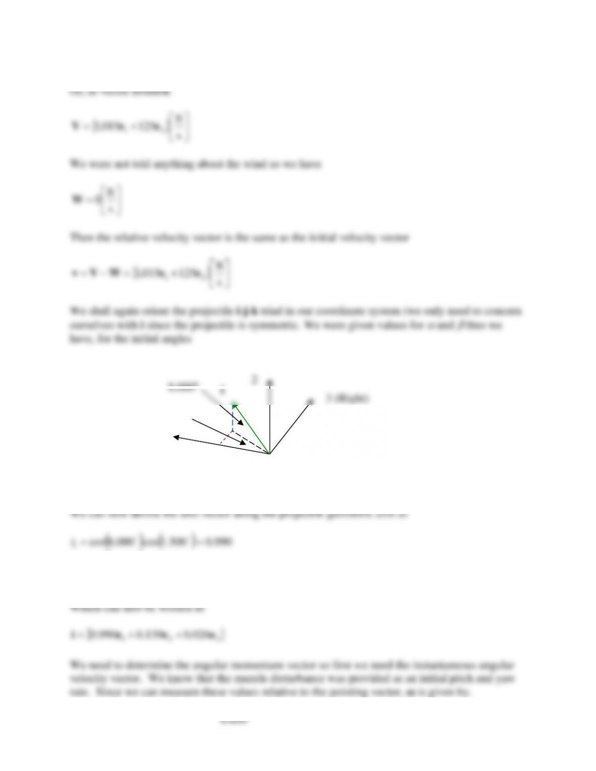
1 (down range axis)
V
45º
2
1=−=
( )
695.044sin
2−=−=
i
( ) ( )
019.0500.1sin44cos
3=−=
i
Which can also be written as
321 019.0695.0719.0 eeei +−=
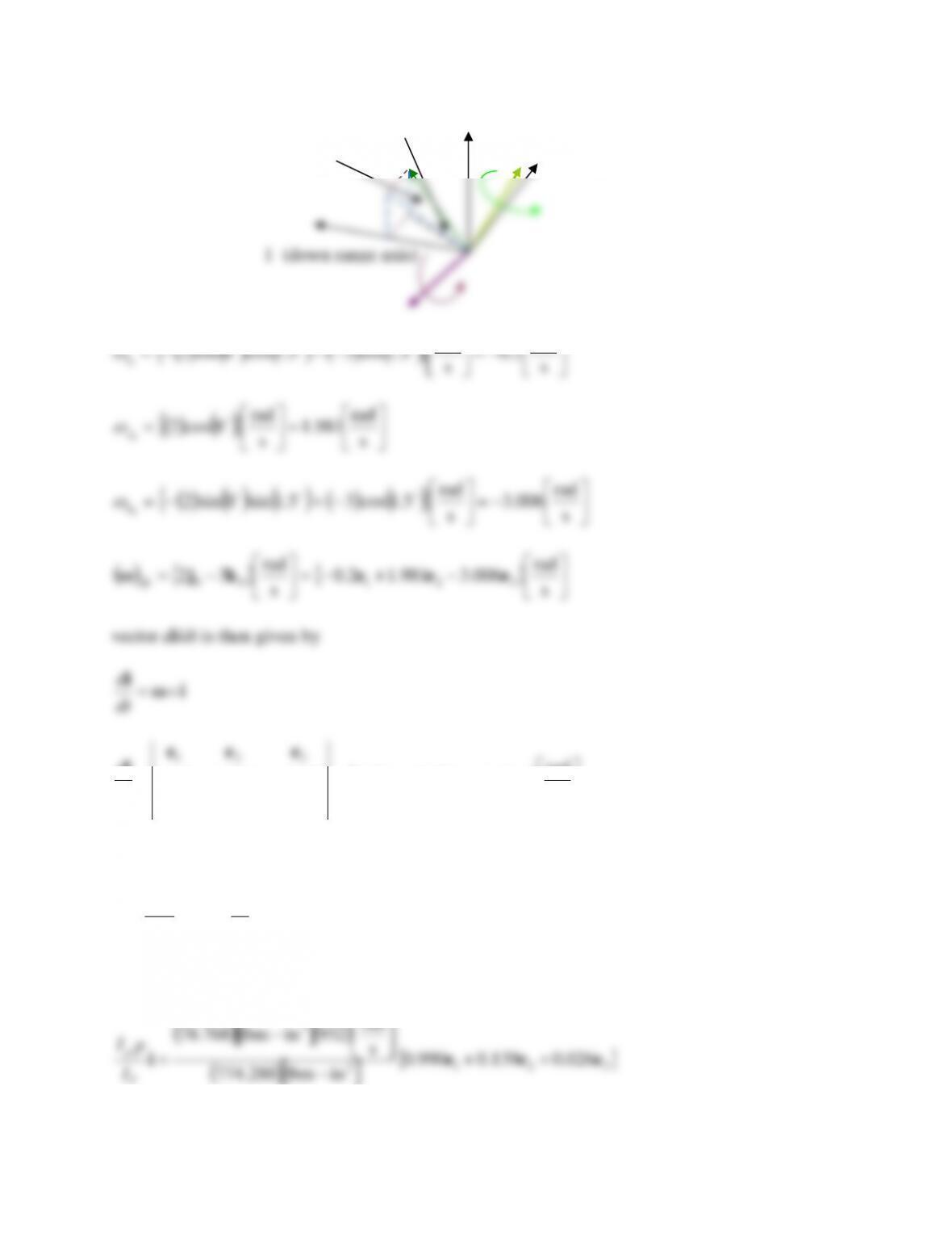
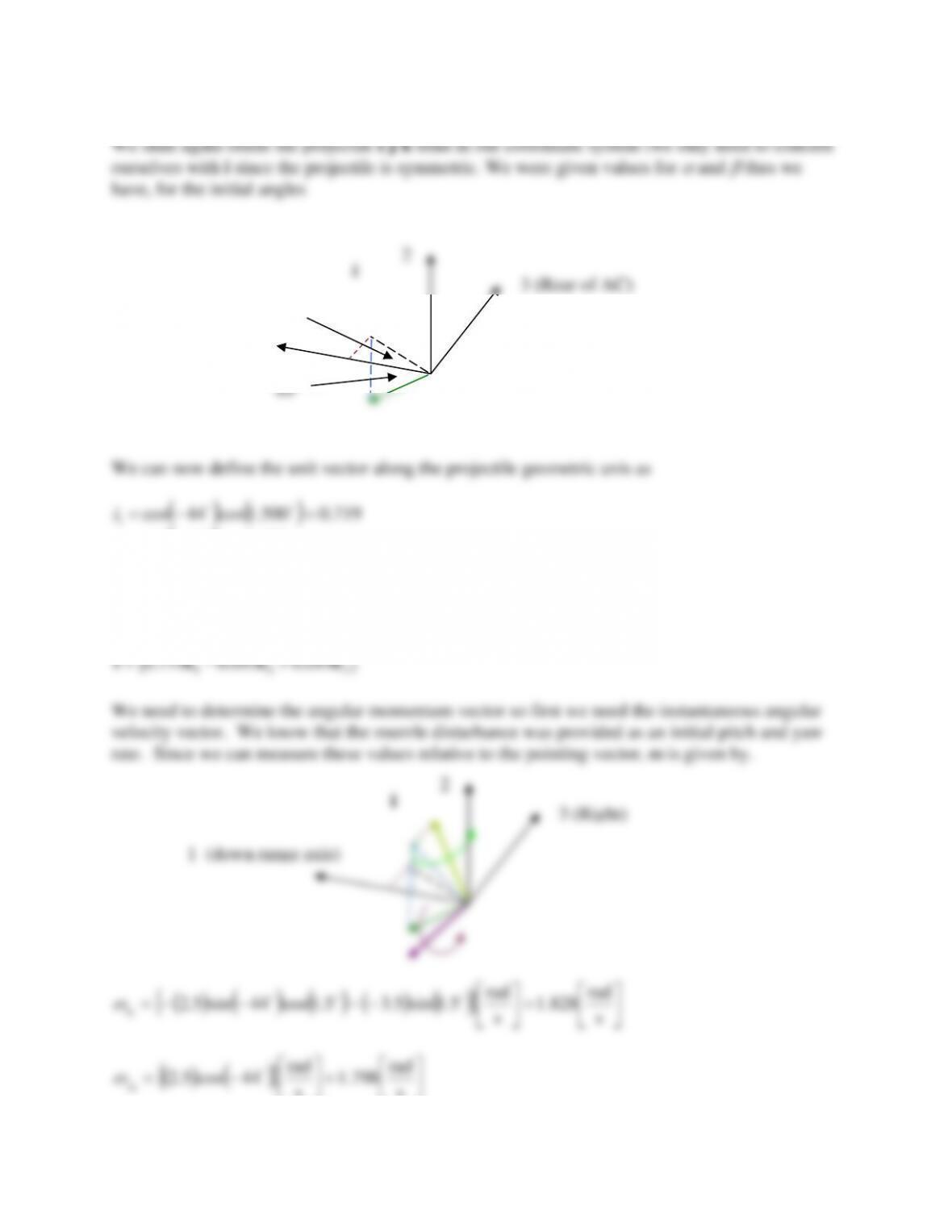
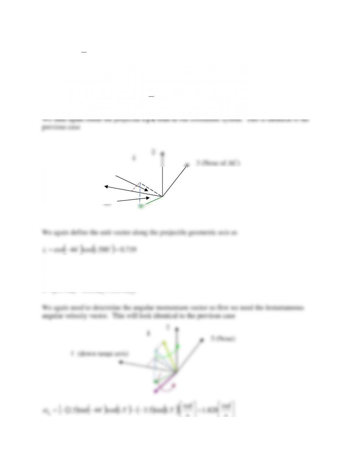
We need to determine the angular momentum vector so first we need the instantaneous angular
velocity vector. We know that the muzzle disturbance was provided as an initial pitch and yaw
rate. Since we can measure these values relative to the pointing vector, ω is given by.
( )
( ) ( )
( )
( )
=
−−−−= s
rad
828.1
s
rad
5.1sin5.35.1cos44sin5.2
0
i
( )
( )
=
−= s
rad
798.1
s
rad
44cos5.2
0
j
1 (down range axis)
2
3 (Right)
i
1 (down range axis)
3 (Rear of AC)
1.5º
44º
2
( )
( ) ( )
( )
( )
−=
−+−−= s
rad
453.3
s
rad
5.1cos5.35.1sin44sin5.2
0
k
( )
−+=
−= s
rad
453.3798.1828.1
s
rad
5.35.2 32100 eeekjωijk
vector di/dt is then given by
iω
i=
dt
d
−−−=
−
−= s
rad
563.2518.2365.2
019.0695.0719.0
453.3798.1828.1 321
321
eee
eee
i
dt
d
The angular momentum vector, h is then obtained through
+= dt
d
I
pI
T
pi
iih
The first term on the RHS is
( )
( )
( )
321
2
2
019.0695.0719.0
inlbm288.774
s
rad
932inlbm768.78
eeei +−
−
−
=
T
p
I
pI
+−= s
rad
8.19.652.68 321 eeei
T
p
I
pI
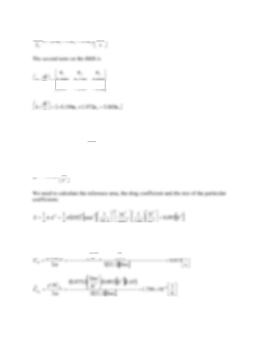
The second term on the RHS is
563.2518.2365.2
019.0695.0719.0
321
−−−
−=
eee
i
idt
d
321 453.3798.1828.1 eee
i
i−+=
dt
d
Then
−−= s
rad
7.11.6470 321 eeeh
The gravitational acceleration vector is
−= 2
2s
ft
2.32 eg
( )
( )
603.06.19sin200.4131.0 2=+=
D
C
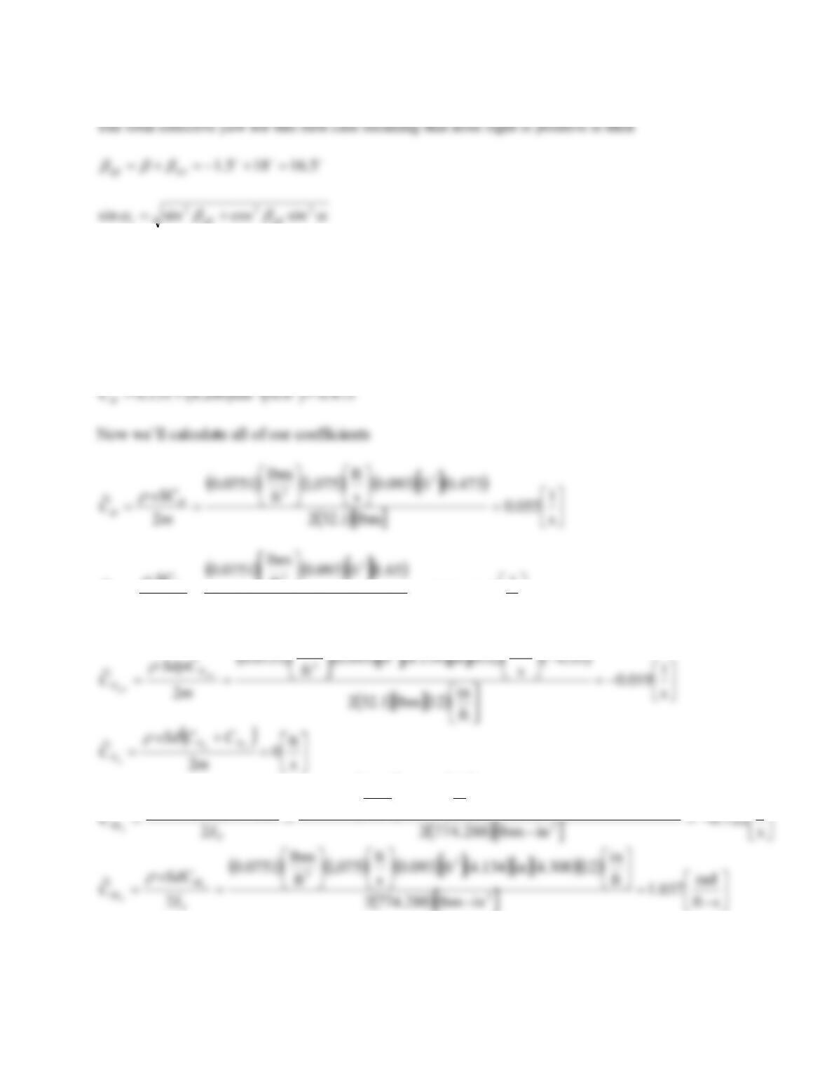
Now we’ll calculate all of our coefficients
( ) ( ) ( )
( )
( )
=
== s
1
071.0
lbm1.322
603.0ft093.0
s
ft
075,1
ft
lbm
0751.0
2
~
2
3
m
vSC
CD
D
( ) ( )
( )
( )
=
== −
ft
1
10799.1
lbm1.322
65.1ft093.0
ft
lbm
0751.0
2
~4
2
3
m
SC
CL
L
( ) ( )
( )
( ) ( )
( )
( )
−=
−
== s
1
019.0
ft
in
12lbm1.322
55.0
s
rad
932in134.4ft093.0
ft
lbm
0751.0
2
~
2
3
m
SdpC
Cp
p
N
N
( )
=
+
=s
ft
0
2
~
m
CCvSd
CNN
N
q
q
( )
( ) ( ) ( )
( )
( )
( )
−=
−
=
+
=s
1
722.0
in–lbm288.7742
7.8in134.4ft093.0
s
ft
075,1
ft
lbm
0751.0
2
~
2
2
2
2
3
2
T
MM
MI
CCvSd
Cq
q
( ) ( ) ( )
( )
( )( )
( )
=
== s–ft
rad
037.1
in–lbm288.7742
ft
in
12300.4in134.4ft093.0
s
ft
075,1
ft
lbm
0751.0
2
~
2
2
3
T
M
MI
vSdC
C
( ) ( )
( )
( ) ( )
( )
−=
−
== s–ft
rad
003.0
in–lbm288.7742
04.0
s
rad
932in134.4ft093.0
ft
lbm
0751.0
2
~
2
2
2
2
3
2
T
M
MI
pCSd
Cp
p
( ) ( ) ( )
( )
( ) ( )
( )
−=
−
== 22
2
2
2
3
2
s
rad
168.2
in–lbm288.7742
028.0
s
rad
932in134.4ft093.0
s
ft
075,1
ft
lbm
0751.0
2
~
T
l
lI
pCSdv
Cp
p
Now we have direct substitutions into the equations of motion to obtain the accelerations. Rather
than write each one out, I solved the vector equations using MathCAD. The equations are
( )
( )
Λgivvivv
V++++−=
p
NLD CCC
dt
d~~~
(8.320)
( )
( ) ( )
( )
iihhiivvivi
h−+−+++= qpP MMMll CCCCC
dt
d~~~~~
(8.321)
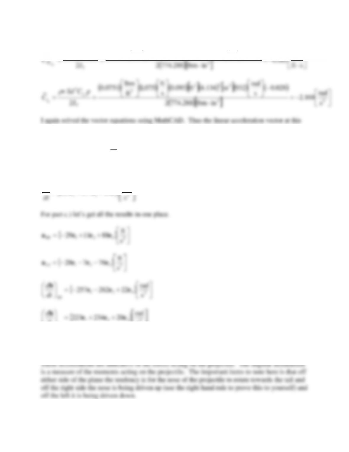
Thus the linear acceleration vector at this instant in time is
++−= 2
321 s
ft
881129 eeea
The angular acceleration vector is then
+−−= 2
321 s
rad
22262257 eee
h
dt
d
For part b.) we need to change some things around. Let’s again get the velocity vector and
position vector of the projectile. This situation is depicted below.
1 (down range axis)
2
3 (Nose of AC)
45º
−= s
ft
333 3
eW
Then the relative velocity vector is
+−=−= s
ft
333723723 321 eeeWVv
1=−=
( )
695.044sin
2−=−=
i
( ) ( )
019.0500.1sin44cos
3=−=
i
321 019.0695.0719.0 eeei +−=
1 (down range axis)
3 (Nose of AC)
1.5º
44º
2
( )
( )
=
−= s
rad
798.1
s
rad
44cos5.2
0
j
( )
( ) ( )
( )
( )
−=
−+−−= s
rad
453.3
s
rad
5.1cos5.35.1sin44sin5.2
0
k
( )
−+=
−= s
rad
453.3798.1828.1
s
rad
5.35.2 32100 eeekjωijk
vector di/dt is again
iω
i=
dt
d
−−−=
−
−= s
rad
563.2518.2365.2
019.0695.0719.0
453.3798.1828.1 321
321
eee
eee
i
dt
d
The angular momentum vector, h is then obtained through
+= dt
d
I
pI
T
pi
iih
Which, as before is
−−= s
rad
7.11.6470 321 eeeh
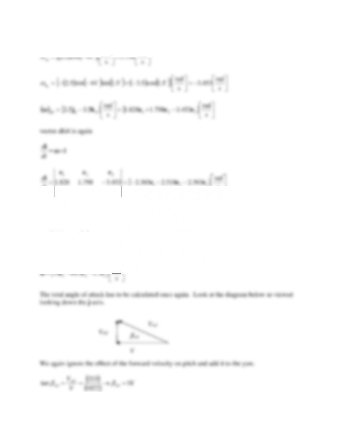
The total angle of attack has to be calculated once again. Look at the diagram below as viewed
looking down the j-axis.
We again ignore the effect of the forward velocity on pitch and add it to the yaw.
( )
( )
18
1022
333
tan =→== rel
AC
rel V
V
V
VAC
Vrel
βrel
6.16=
t
The drag coefficient is
2
20
DDD CCC +=
( )
( )
473.06.16sin200.4131.0 2=+=
D
C
Now we’ll calculate all of our coefficients
( ) ( ) ( )
( )
( )
=
== s
1
055.0
lbm1.322
473.0ft093.0
s
ft
075,1
ft
lbm
0751.0
2
~
2
3
m
vSC
CD
D
( ) ( )
( )
( )
=
== −
ft
1
10799.1
lbm1.322
65.1ft093.0
ft
lbm
0751.0
2
~4
2
3
m
SC
CL
L
( ) ( )
( )
( ) ( )
( )
( )
−=
−
== s
1
019.0
ft
in
12lbm1.322
55.0
s
rad
932in134.4ft093.0
ft
lbm
0751.0
2
~
2
3
m
SdpC
Cp
p
N
N
( )
=
+
=s
ft
0
2
~
m
CCvSd
CNN
N
q
q
( )
( ) ( ) ( )
( )
( )
−
+
1
7.8in134.4ft093.0
s
ft
075,1
ft
lbm
0751.0
~
2
2
2
3
2
MM
CCvSd
( ) ( )
( )
( ) ( )
−
rad
04.0
s
rad
932in134.4ft093.0
ft
lbm
0751.0
~
2
2
2
3
2
M
pCSd
instant in time is
−−−= 2
321 s
ft
76728 eeea
The angular acceleration vector is then
++= 2
321 s
rad
20234223 eee
h
dt
d
9.3 Wind Effects on a Simple Air Trajectory
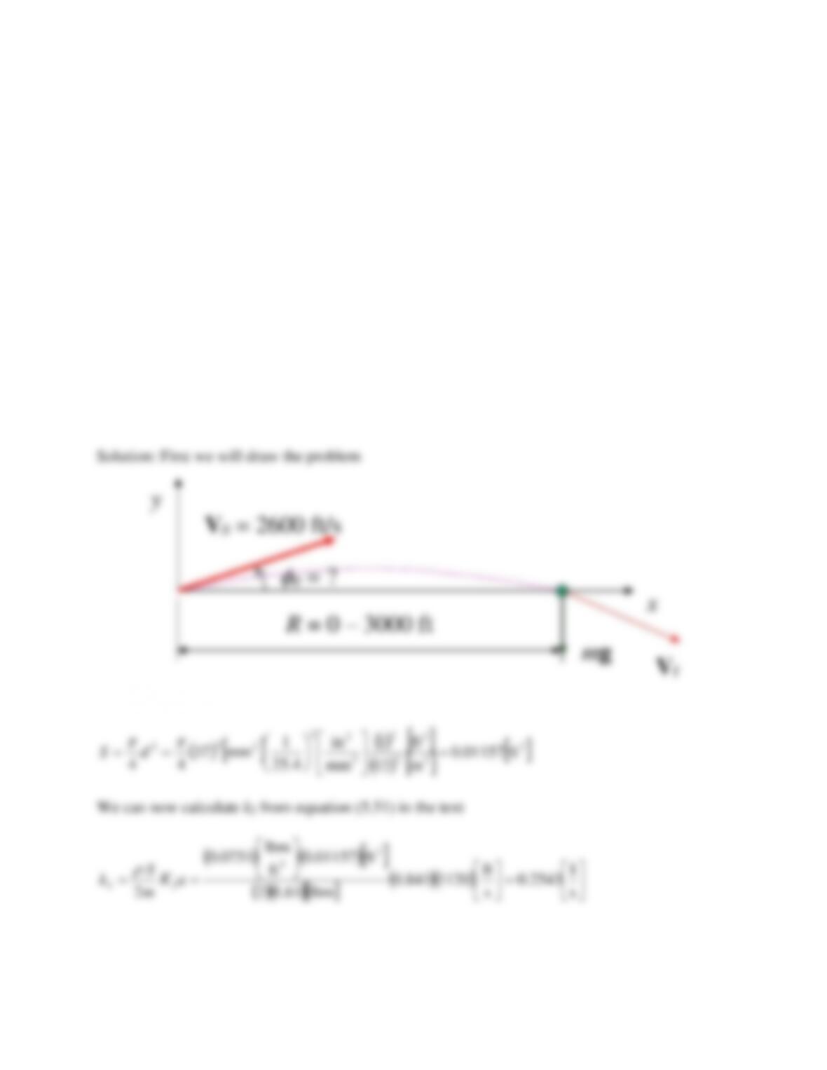
Problem 29 – A U.S. 37 mm AP projectile is fired with a Muzzle velocity of 2600 [ft/s]. The
projectile weighs 1.61 lbm. Assuming flat fire with K2 = 0.841 [unitless] and using standard sea
level met data (
= 0.0751 lbm/ft3, a = 1120 ft/s)
a) Create a table containing range (yards), impact velocity (ft/s), time of flight (TOF)
(s), initial quadrant elevation (QE) angle (minutes) and angle at impact (minutes)
in 200 yard increments out to 1000 yards assuming no wind effects.
Answer: at 1000 yards V = 1837 ft/s
b) Determine the deflection of the projectile with a 20 mi/hr crosswind blowing from
left to right as viewed from behind the weapon.
Answer: at 1000 yards z = 6.217 ft
c) Determine the impact velocity, change in TOF and how high the projectile will hit
if fired at the same QE’s with a 20 mi/hr tailwind and no crosswind.
Answer: The projectile will hit 1.402 inches higher than expected.
We shall first calculate the projectile reference area in consistent units
( )( )
s
lbm61.12
2
22 aK
m
Now that we have k2 defined, we can create the table in order. Note that since we have assumed
that K2 is constant in this development, k2 is also constant. We will first call on
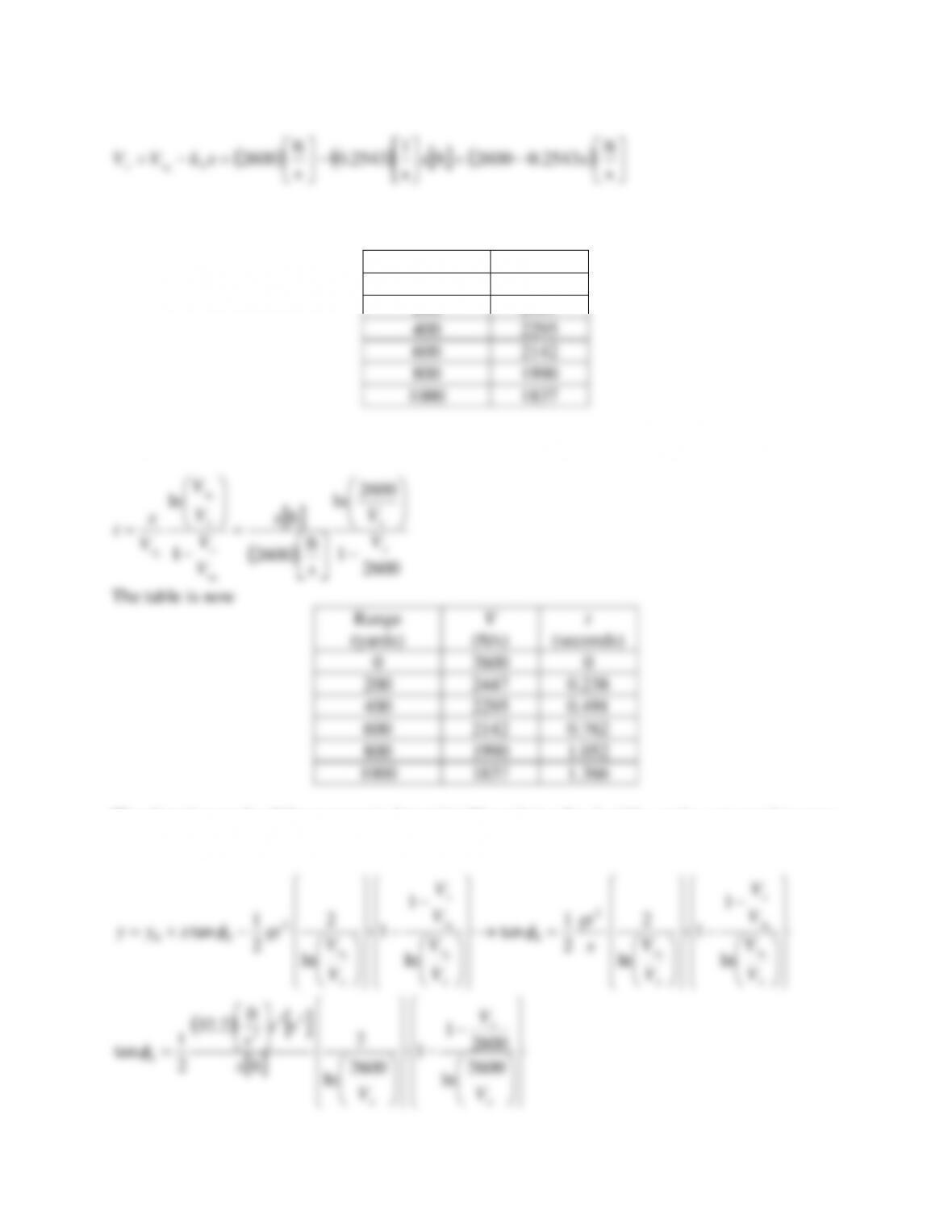
s
s
2
0xxxkVV xx
Our table now appears like this
Range (yards)
V (ft/s)
0
2600
200
2447
400
2295
600
2142
800
1990
1000
1837
Now that we have the impact velocity we can obtain the time of flight from
(ft/s)
0
2600
200
2447
400
2295
600
2142
800
1990
1000
1837
Using the above relation we obtain the angle multiply this by 60 to obtain the angle in minutes.
Range
(yards)
V
(ft/s)
t
(seconds)
0
(minutes)
0
2600
0
–
200
2447
0.238
5.11
400
2295
0.491
10.67
600
2142
0.762
16.73
800
1990
1.052
23.39
1000
1837
1.366
30.75
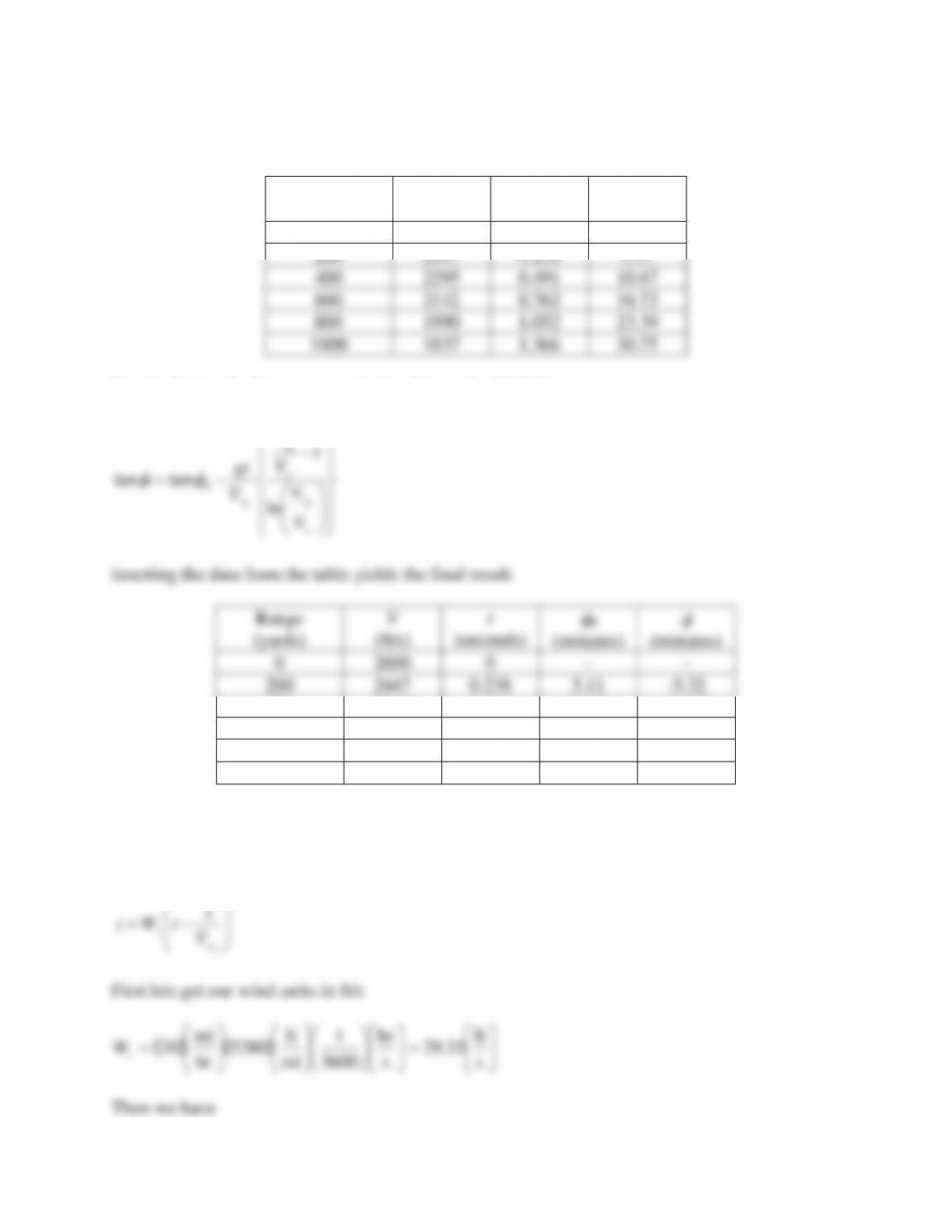
For the final task of part a) we calculate the angle of fall from
−
−=
x
x
x
x
x
V
V
V
V
V
gt
0
0
0ln
1
tantan 0
inserting the data from the table yields the final result
Range
(yards)
V
(ft/s)
t
(seconds)
0
(minutes)
(minutes)
0
2600
0
–
–
200
2447
0.238
5.11
-5.32
400
2295
0.491
10.67
-11.59
600
2142
0.762
16.73
-19.04
800
1990
1.052
23.39
-27.96
1000
1837
1.366
30.75
-38.77
For part b we only require:
−=
0
x
zV
x
tWz
First lets get our wind units in ft/s
( ) ( )
=
=s
ft
33.29
s
hr
3600
1
mi
ft
5280
hr
mi
20
z
W
Then we have
( )
−
=
s
ft
2600
ft
s
s
ft
33.29 x
tz
And our table can be expanded to
Range
(yards)
V
(ft/s)
t
(seconds)
0
(minutes)
(minutes)
z
(ft)
0
2600
0
–
–
–
200
2447
0.238
5.11
-5.32
0.207
400
2295
0.491
10.67
-11.59
0.863
600
2142
0.762
16.73
-19.04
2.029
800
1990
1.052
23.39
-27.96
3.783
1000
1837
1.366
30.75
-38.77
6.217
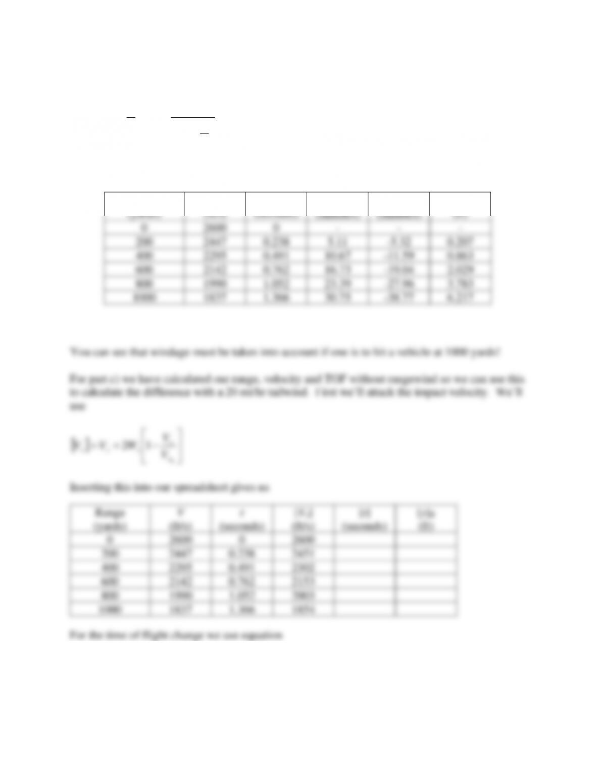
You can see that windage must be taken into account if one is to hit a vehicle at 1000 yards!
For part c) we have calculated our range, velocity and TOF without rangewind so we can use this
to calculate the difference with a 20 mi/hr tailwind. First we’ll attack the impact velocity. We’ll
use
−+=
0
12
x
x
xxx V
V
WVV
Inserting this into our spreadsheet gives us
For the time of flight change we use equation
Range
(yards)
V
(ft/s)
t
(seconds)
[Vx]
(ft/s)
[t]
(seconds)
[y]R
(ft)
0
2600
0
2600
200
2447
0.238
2451
400
2295
0.491
2302
600
2142
0.762
2153
800
1990
1.052
2003
1000
1837
1.366
1854