100
2
−
=
D
DD
C
CC
Error
est
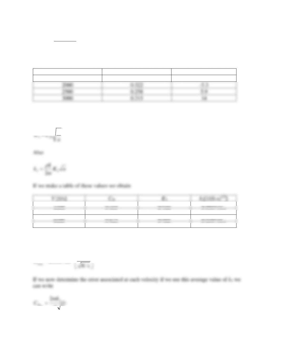
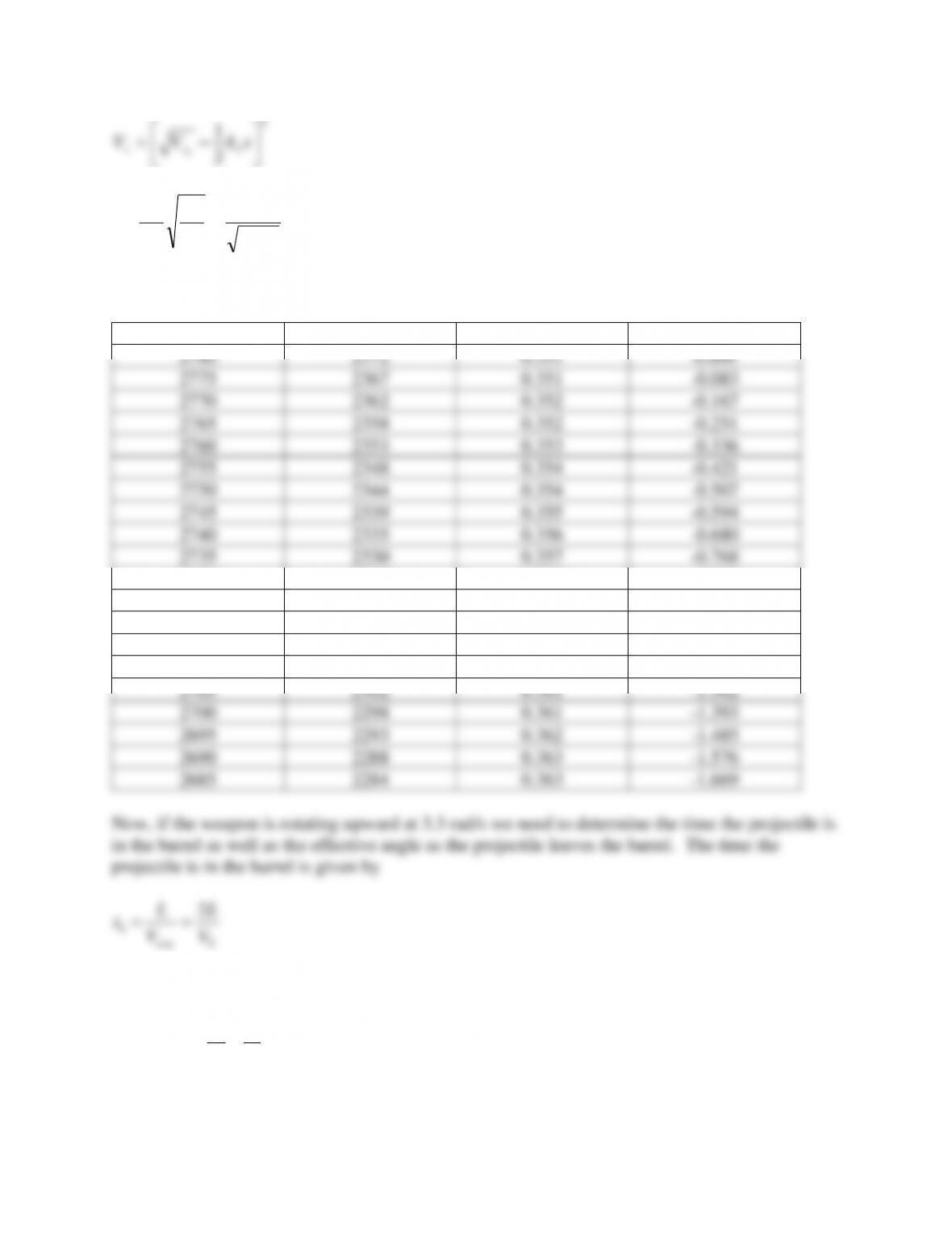
Putting this in a table yields
V [ft/s]
CDest
Error2[%]
1500
0.430
-21
2000
0.322
-5.3
2500
0.258
5.9
3000
0.215
14
Finally let’s look at the third model where we see that
a
V
CK D
=
3
Also
aK
m
S
k33 2
=
If we make a table of these values we obtain
V [ft/s]
CD
K3
k3[1/(ft-s)1/2]
1500
0.354
0.410
8.964×10⁻³
2000
0.306
0.409
8.948×10⁻³
2500
0.274
0.409
8.958×10⁻³
3000
0.250
0.409
8.953×10⁻³
We will have to take an average value for k3 from this table and we obtain
= −
sft
1
10956.8 3
3AVG
k
VS
mk
CAVG
est
D
3
2
=
and
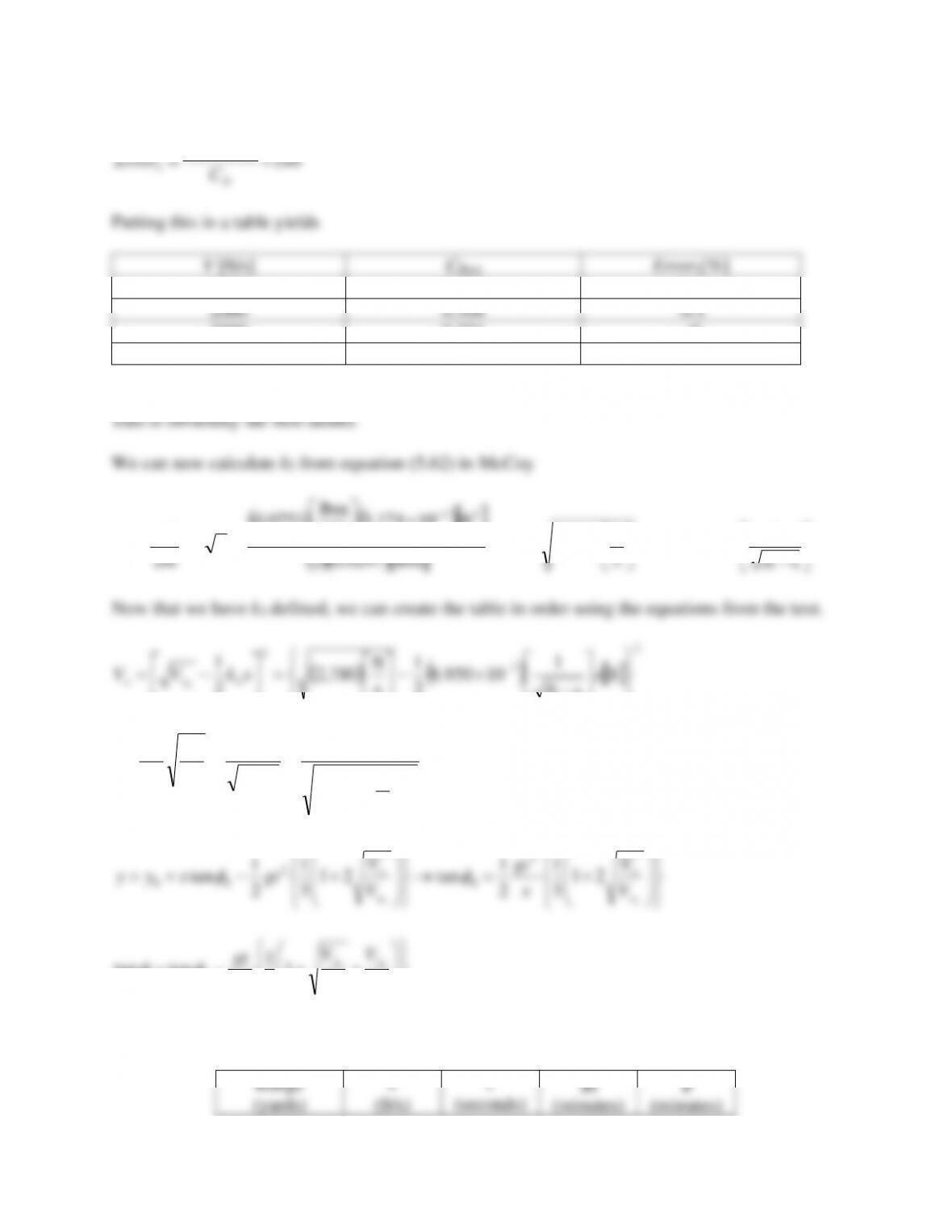
−
DD
CC
est
0
2780.0
0.000
–
–
100
2640.2
0.111
2.224
-2.302
200
2504.1
0.227
4.608
-4.941
300
2371.5
0.351
7.171
-7.972
400
2242.6
0.481
9.930
-11.459
500
2117.2
0.618
12.908
-15.477
600
1995.5
0.764
16.130
-20.117
Let’s examine the headwind. In this case the weapon elevations are set in the above table and we
want to see how much higher or lower the projectile will be at the given range.
−+=
0
12
x
x
xxx V
V
WVV
(WT-51)
0
2780
0.000
0
–
100
2638
0.111
-0.0012
0
200
2500
0.228
-0.0099
0
300
2366
0.351
-0.0355
0
400
2235
0.481
-0.0898
0
500
2108
0.620
-0.1873
0
600
1984
0.766
-0.3465
0
0.000
0
100
0.111
200
0.227
300
0.351
400
0.481
500
0.618
600
0.764

Hint: the muzzle rise will affect the initial launch angle but the flatter trajectory will compensate
to some degree. Although not done in practice, for this calculation, start at the high muzzle
2
3
2
1
0
−= xkVV xx
0
0
0xx
x
x
xVV
x
V
V
V
x
t==
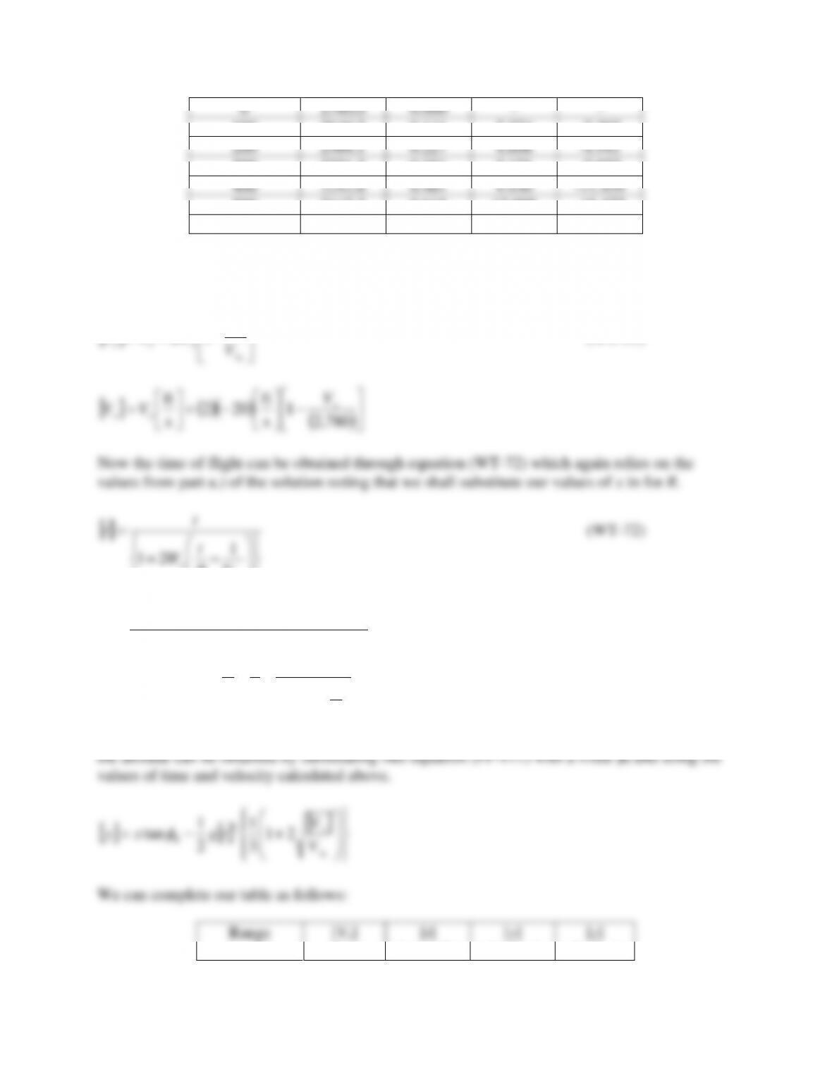
The tabulated results are then
V0 [ft/s]
V300 [ft/s]
t [s]
y [in]
2780
2372
0.351
0.000
2775
2367
0.351
-0.083
2770
2362
0.352
-0.167
2765
2358
0.352
-0.251
2760
2353
0.353
-0.336
2755
2348
0.354
-0.421
2750
2344
0.354
-0.507
2745
2339
0.355
-0.594
2740
2335
0.356
-0.680
2735
2330
0.357
-0.768
2730
2325
0.357
-0.856
2725
2321
0.358
-0.944
2720
2316
0.359
-1.033
2715
2312
0.359
-1.122
2710
2307
0.360
-1.212
2705
2302
0.361
-1.302
2700
2298
0.361
-1.393
2695
2293
0.362
-1.485
2690
2288
0.363
-1.576
2685
2284
0.363
-1.669
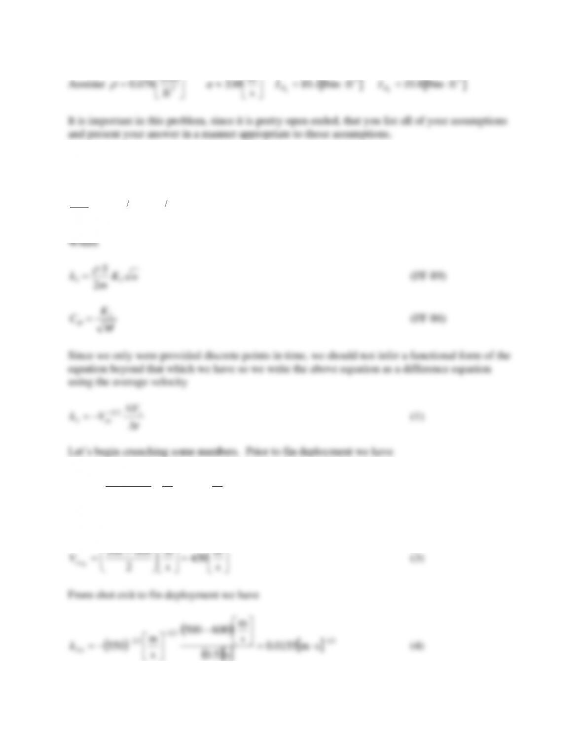
0
V
V
avg
b==
The barrel length was given as
( )
ft833.1
in
ft
12
1
in22 =
=L
The angle to add to the initial angle is
( )( )
( )
== s
rad
3.3
s
ft
ft833.12
0
V
tbmuz
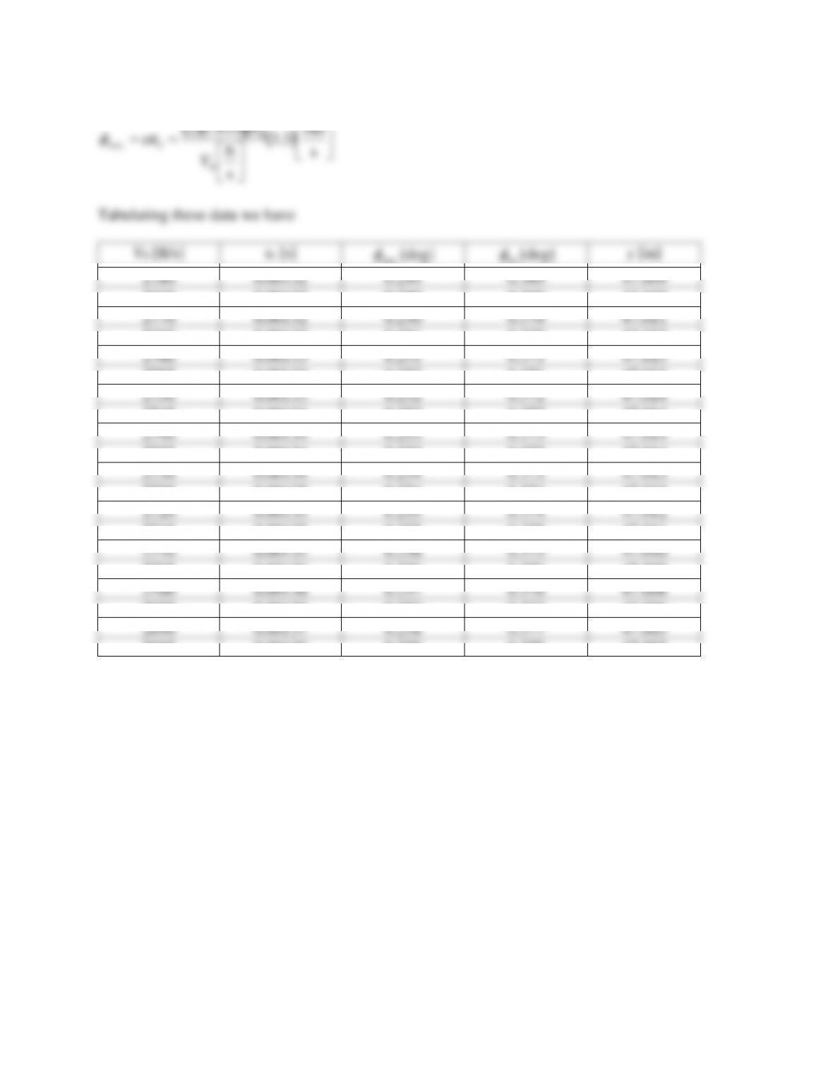
Tabulating these data we have
V0 [ft/s]
tb [s]
muz
[deg]
tot
[deg]
y [in]
2780
0.00132
0.249
0.369
47.009
2775
0.00132
0.250
0.369
47.010
2770
0.00132
0.250
0.370
47.011
2765
0.00133
0.251
0.370
47.012
2760
0.00133
0.251
0.371
47.013
2755
0.00133
0.252
0.371
47.013
2750
0.00133
0.252
0.372
47.014
2745
0.00134
0.253
0.372
47.014
2740
0.00134
0.253
0.373
47.014
2735
0.00134
0.253
0.373
47.014
2730
0.00134
0.254
0.373
47.013
2725
0.00135
0.254
0.374
47.013
2720
0.00135
0.255
0.374
47.012
2715
0.00135
0.255
0.375
47.011
2710
0.00135
0.256
0.375
47.010
2705
0.00136
0.256
0.376
47.009
2700
0.00136
0.257
0.376
47.008
2695
0.00136
0.257
0.377
47.006
2690
0.00137
0.258
0.377
47.005
2685
0.00136
0.258
0.378
47.003
From these data it can be seen that the “sweet spot” is at about 2740 – 2745 ft/s.
Problem 24 – Normally on a fin stabilized projectile the spin damping due to the body is much
smaller than that due to the fins. A 155 mm projectile weighs 101 lbm and is designed so that it
leaves the muzzle of the weapon at 600 m/s and spinning at 220 Hz. After 0.5 seconds fins are
deployed. At this instant in time the spin rate is 197 Hz and the velocity is 500 m/s. After
another 0.5 seconds the projectile has achieved its steady state spin rate of 12 Hz and is at a
velocity of 400 m/s. The changes in polar moment associated with the fin deployment are
provided below (be sure to think about which one is before and which is after). Determine the
following:
a.) The drag coefficient of the both flight configurations
b.) The spin damping coefficient for the body (only) and the fins (only)
c.) The roll coefficient (Clδ) of the fins assuming a 1 degree cant
lbm
m
2
2
Solution: Since this projectile is supersonic the entire time (a ≈ 330 m/s) we shall assume a drag
coefficient proportional to 1/Ma1/2. Thus we can write
dtkdVVVk
dt
dV
xxx
x
3
2323
3−=→−= −
(FF-96)
=
+
=s
m
550
s
m
2
500600
A
av
V
(2)
After fin deployment we have
=
+
=s
m
450
s
m
2
400500
B
av
V
(3)
From shot exit to fin deployment we have
( ) ( )
( )
21
23
23
3sm0155.0
s5.0
s
m
600500
s
m
550 −
−
−=
−
−=
A
k
(4)
( ) ( )
( )
21
23
23
3sm0210.0
s5.0
s
m
500400
s
m
450 −
−
−=
−
−=
B
k
(5)
05.2−
p
l
C
(18)
We can now determine the roll moment applied by the fins through
lFl CSdVM 2
2
1
=
(FT-6)
p
l
F
lC
V
dp
C
– =
(20)
Inserting the numbers yields
( ) ( ) ( )
( )
( ) ( )
45.306.2
s
m
400
deg
rad
360
2
deg0.1
m155.0
rev
rad
2
s
rev
12
=−
−=
l
C
(21)
Problem 25 – In a test range a 0.50 caliber M33 ball projectile is fired at an elevation of 10º with
a muzzle velocity of 3,013 ft/s. The initial pitch and yaw angles are 1.030º and 1.263º,
respectively. The initial pitch and yaw rates are 2 rad/s nose down and 1 rad/s nose left,
respectively. If the projectile has the coefficients below at this particular instant, write the
acceleration vector and the angular momentum vector.
Please ignore the Coriolis acceleration and assume the weapon has a right hand twist.
Projectile Information
01.0
69.2
88.2
2938.0
−=
=
=
=
p
N
L
M
D
C
C
C
C
( )
( )
=
=
=+
−=+
3
ft
lbm
0751.0
05.0
004.0
5.5
p
q
q
M
NN
MM
C
CC
CC
=
=
=
=
s
rad
404,15
g02.42
cm–g5.74
cm–g85.7
2
2
p
m
I
I
T
P
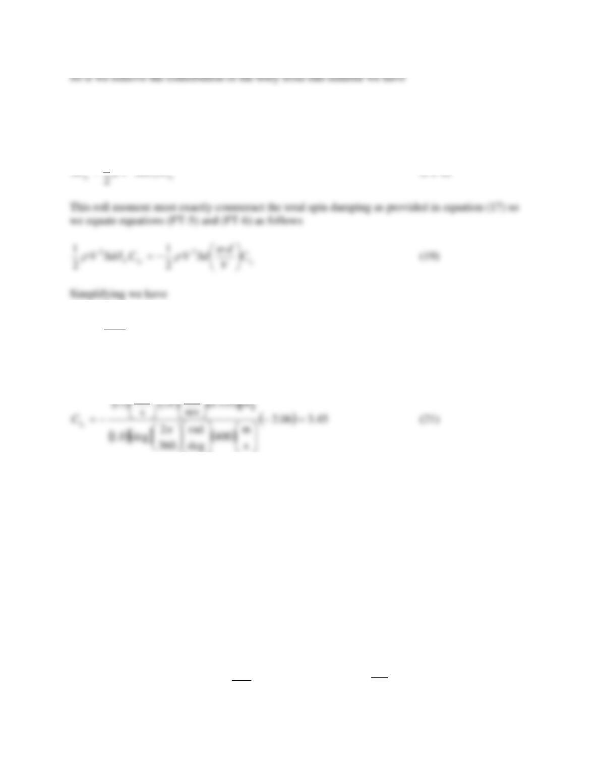
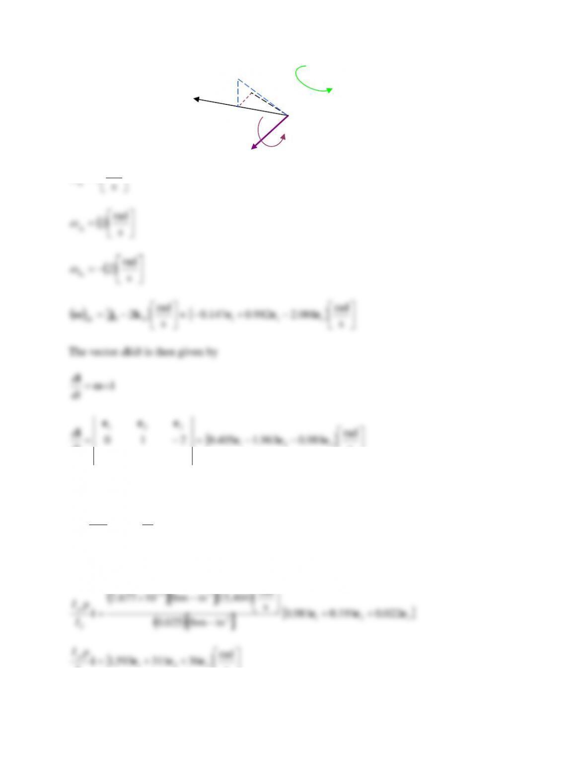
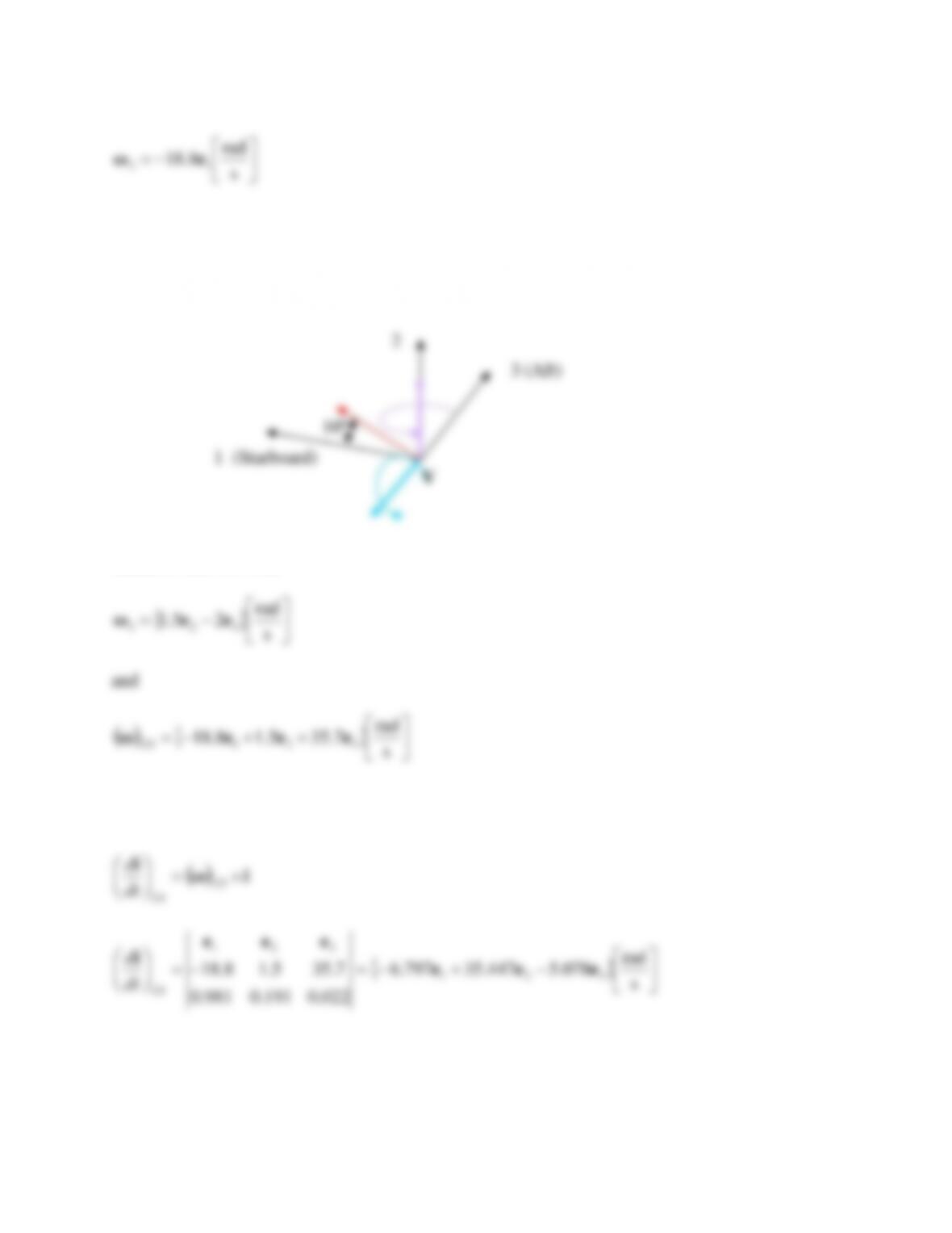
Please supply all answers in an inertial coordinate system labeled 1,2,3 with 1 being along the
downrange direction and 3 being to the right side. Treat all missing coefficients as equal to zero.
It is very important that you DRAW the situation.
+= s
ft
523968,2 21 eeV
We were not told anything about the wind so we have
=s
ft
0W
Then the relative velocity vector is the same as the initial velocity vector
+=−= s
ft
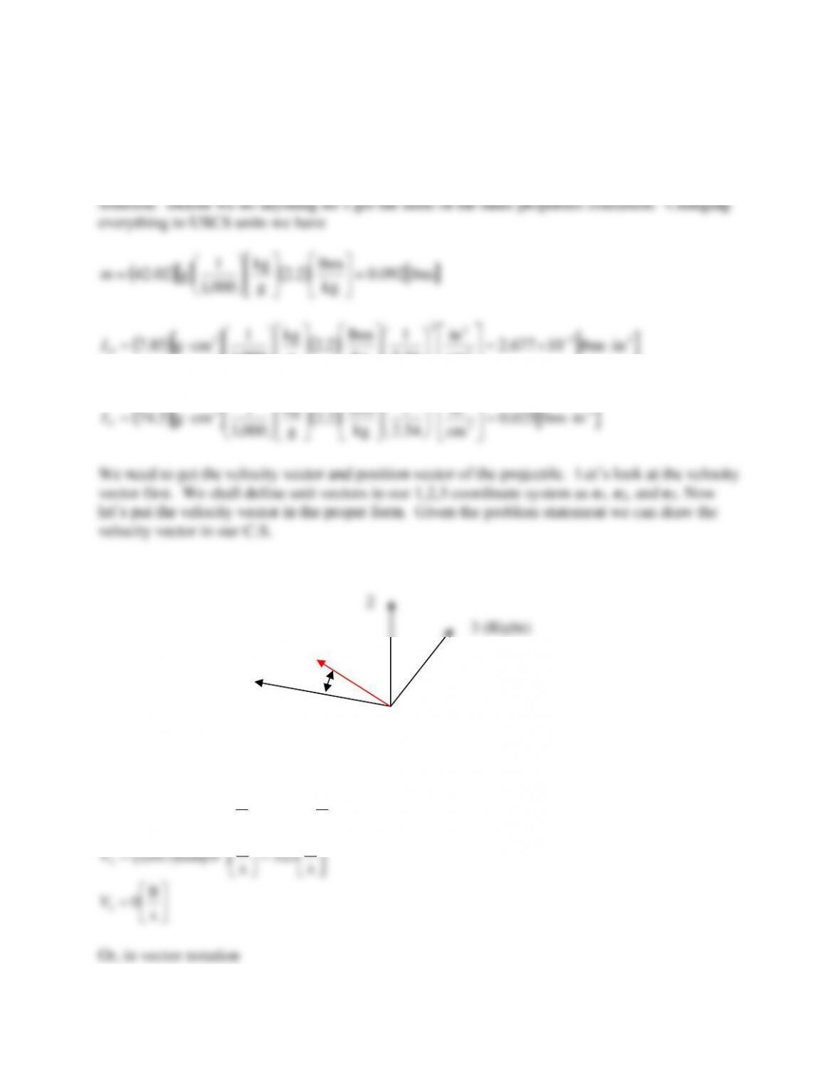
523968,2 21 eeWVv
We shall again orient the projectile i–j–k triad in our coordinate system (we only need to concern
ourselves with i since the projectile is symmetric. We were given values for
and
thus we
have, for the initial angles
2==
( )
022.0263.1sin
3==
i
Which can also be written as
321 022.0191.0981.0 eeei ++=
We need to determine the angular momentum vector so first we need the instantaneous angular
velocity vector. We know that the muzzle disturbance was provided as an initial pitch and yaw
rate. Since we measure these values relative to the pointing vector, ω is given by.
2
3 (Right)
i
11.030º
2
3 (Right)
i
1.263º
11.030º
1.263º
=s
rad
0
0
i
1 (down range axis)
( )
( ) ( )
( )
( )
( )
( )
( )
=
=
+
=−
−
s
ft
10782.2
ft
in
12lbm092.02
004.0in5.0ft10364.1
s
ft
013,3
ft
lbm
0751.0
2
~4
23
3
m
CCvSd
CNN
N
q
q
( )
( ) ( )
( )
( )
( )
( )
−=
−
=
+
=
−
s
1
351.8
in–lbm025.02
5.5in5.0ft10364.1
s
ft
013,3
ft
lbm
0751.0
2
~
2
2
2
23
3
2
T
MM
MI
CCvSd
Cq
q
( ) ( )
( )
( )
( )( )
( )
=
==
−
s–ft
rad
9.104
in–lbm025.02
ft
in
1288.2in5.0ft10364.1
s
ft
013,3
ft
lbm
0751.0
2
~
2
23
3
T
M
MI
vSdC
C
( )
( )
( )
( ) ( )
( )
=
==
−
s–ft
rad
388.0
in–lbm025.02
05.0
s
rad
404,15in5.0ft10364.1
ft
lbm
0751.0
2
~
2
2
2
23
3
2
T
M
MI
pCSd
Cp
p
Now we have direct substitutions into the equations of motion to obtain the accelerations. Rather
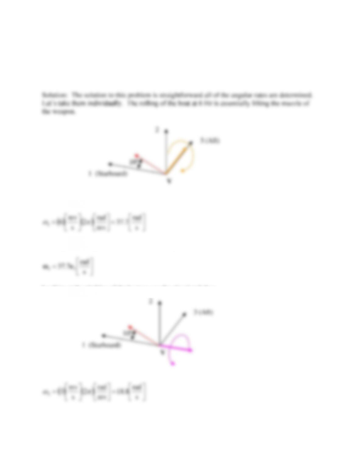
weapon is pointed directly to starboard and has the same elevation as in the test firing (i.e. 10º),
find the values for the acceleration and angular momentum as was done in problem 25.
Comment on the results. For a proper comparison use the same coordinate system as in problem
25 but now with the 1 direction pointing to starboard and the 3 direction pointing to the stern of
the boat. Once again the drawings are important.
Writing an expression for the motion we first will convert from Hz to rad/s
rev
s
1
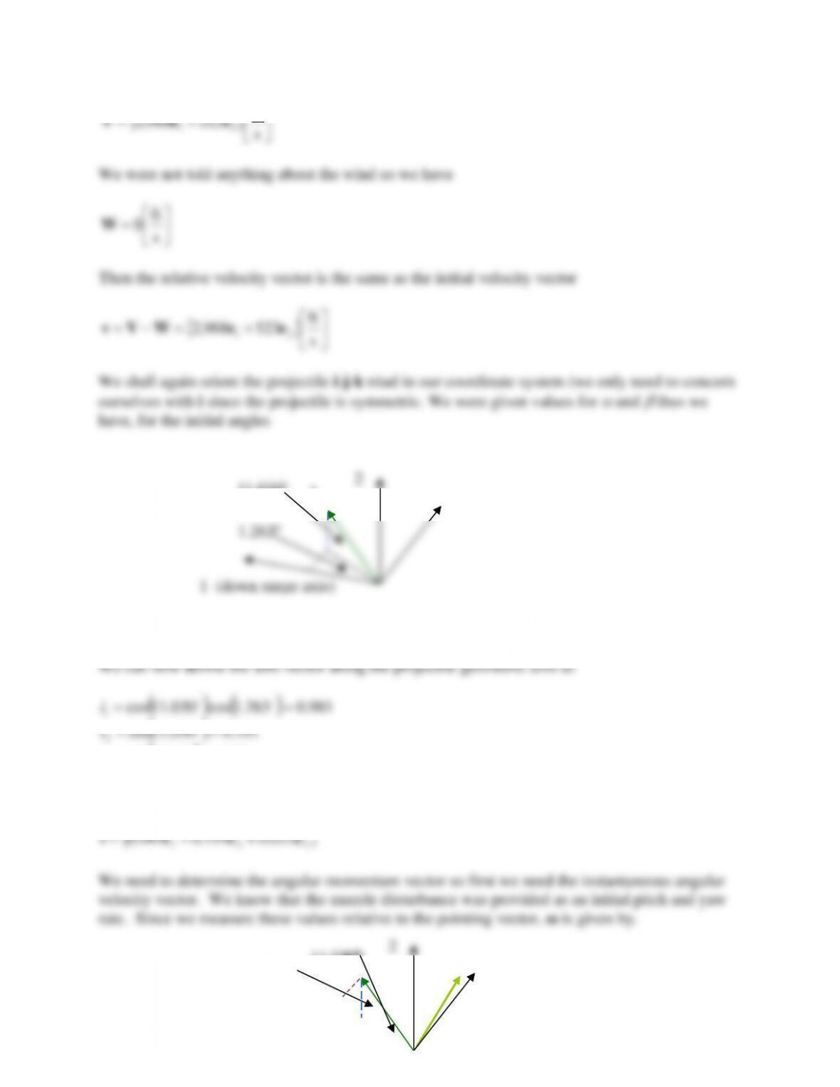
Looking at the diagram we see that this is completely in the 3 direction therefore we have
Looking at the pitching of the boat we see the situation below
rev
s
2
Looking at the diagram we see that this is completely in the -1 direction therefore we have
For the gunners motions we can put them both on one drawing we have
Based on this we write
123 eeeω
Since the vector di/dt was written in terms of the three coordinate axes we can find the total
angular rate as follows. Lets look at just the rotation of the coordinate system first.
( )
iω
i=
123
CS
dt
d
−+−=−=
s
rad
078.5447.35797.6
022.0191.0981.0
7.355.18.18 321
321
eee
eee
i
CS
dt
d
The vector di/dt is then given by
CStotal dt
d
dt
d
dt
d
+=
iii
−+−=
s
rad
060.6484.33392.6 321 eee
i
total
dt
d
In this case, the boat is moving so the “wind” will be coming from the bow at 40 knots or
and
At this point we need to recalculate the angular momentum because of the movement of the
weapon platform. When the platform was stationary we saw that we had
Now we calculate the angular momentum as
I
T
The first term on the RHS is identical to that calculated in problem 25. The second term on the
RHS is
321 09.34805.5898.1 eee
Then
++= s
rad
70316591,1 321 eeeh
The coefficients do not change appreciably. Again calculating the acceleration and angular
momentum vectors we obtain
321 s
dt
We see, in comparison with the answers to problem 1 that we more than doubled the acceleration
to the right side of the weapon and doubled our angular accelerations in the 1 and 2 directions. If
the projectile were marginally stable, this might cause large issues.
Problem 27 – In a test range a modified 105mm M1 projectile is fired at an elevation of 7º with a
muzzle velocity of 1,022 ft/s. The initial pitch and yaw angles are 1.0º and 1.5º, respectively.
The initial pitch and yaw rates are 3 rad/s nose down and 2 rad/s nose left, respectively. If the
projectile has the coefficients below at this particular instant, write the acceleration vector and
the angular momentum vector.
Please ignore the Coriolis acceleration and assume the weapon has a right hand twist.
Projectile Information
55.0
65.1
30.4
20.4
131.0
2
−=
=
=
=
=
p
N
L
M
D
D
C
C
C
C
C
( )
( )
=
−=
−=
+
−=+
3
ft
lbm
0751.0
028.0
892.0
0
7.8
p
p
q
q
l
M
NN
MM
C
C
CC
CC
=
=
=
=
s
rad
932
lbm1.32
ft–lbm377.5
ft–lbm547.0
2
2
p
m
I
I
T
P
Please supply all answers in an inertial coordinate system labeled 1,2,3 with 1 being along the
downrange direction and 3 being to the right side. Treat all missing coefficients as equal to zero.
It is very important that you DRAW the situation. This will have a great deal of influence in
obtaining the correct answer