Unlock document.
This document is partially blurred.
Unlock all pages and 1 million more documents.
Get Access
7 Introductory Concepts
Problem 1 - In a test range a 0.50 caliber M33 ball projectile has a velocity vector which is at an
angle of 10º to the horizontal (assume zero azimuth) with a velocity of 3,013 ft/s. The initial
pitch and yaw angles are 1.030º and 1.263º, respectively. The initial rotational rate of change of
the axial unit vector (dx/dt) is provided below. If the projectile has the coefficients below at this
particular instant, draw the situation and determine the following:
a.) Velocity vector (ft/s)
b.) Projectile axial unit vector (x)
c.) Drag force vector (lbf)
d.) Spin damping moment vector (lbf-in)
e.) Overturning moment vector (lbf-in)
f.) Magnus moment vector (lbf-in)
2
cm
54.2
kg
g
000,1
P
( )
( )
2
2
2
2
2inlbm025.0
cm
in
54.2
1
kg
lbm
2.2
g
kg
000,1
1
cmg5.74 =
=
T
I
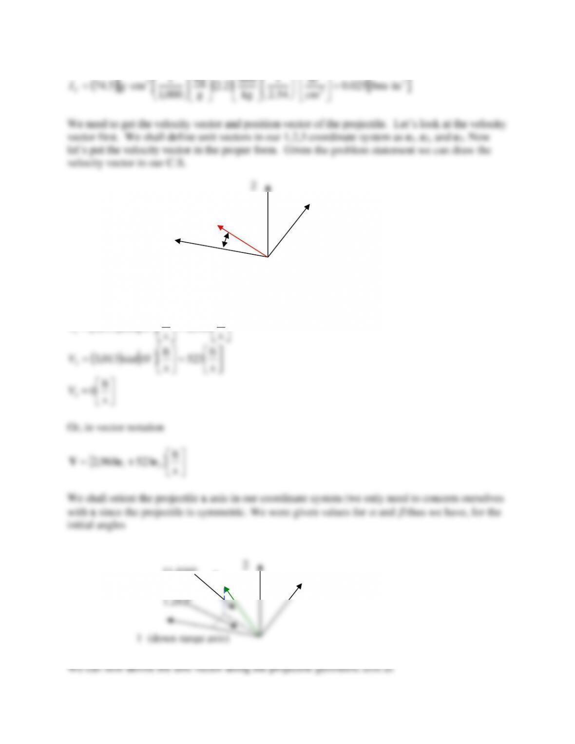
We need to get the velocity vector and position vector of the projectile. Let’s look at the velocity
vector first. We shall define unit vectors in our 1,2,3 coordinate system as e1, e2, and e3. Now
let’s put the velocity vector in the proper form. Given the problem statement we can draw the
velocity vector in our C.S.
From the above diagram it is obvious that in the 1 direction we have
( )
( )
=
=s
ft
968,2
s
ft
10cos013,3
1
V
( )
( )
=
=s
ft
523
s
ft
10sin013,3
2
V
=s
ft
0
3
V
Or, in vector notation
+= s
ft
523968,2 21 eeV
We shall orient the projectile x axis in our coordinate system (we only need to concern ourselves
with x since the projectile is symmetric. We were given values for
and
thus we have, for the
initial angles
1 (down range axis)
2
3 (Right)
V
10º
2
3 (Right)
x
11.030º
( ) ( )
981.0263.1cos030.11cos
1==
x
( )
191.0030.11sin
2==
x
( )
022.0263.1sin
3==
x
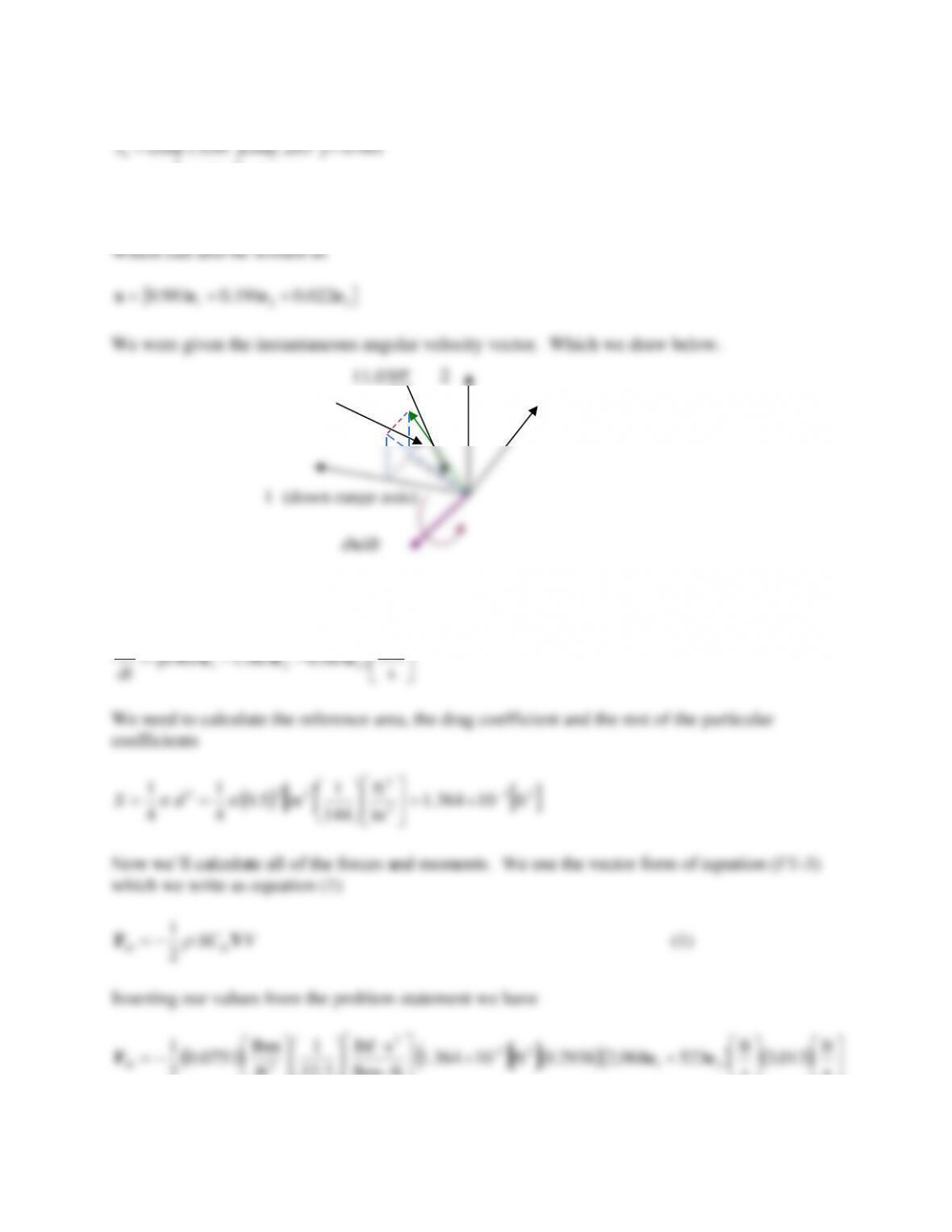
The vector dx/dt was given in the problem statement by
rad
x
d
2
3 (Right)
x
1.263º
11.030º
lbf736.0179.4 21 eeF +−=
D
To find the spin damping moment we use equation (FT-5) but change it to a vector equation by
multiplying the scalar value by a unit vector in the direction opposite to the pointing vector. This
( )
−−=
−
= s
ft
3.665.527.11
8.533.655.11
022.0191.0981.0 321
321
eee
eee
xVx
(4)
Inserting this result into equation (FT-22) yields
( ) ( )
( )
( )
( ) ( )
( ) ( ) ( )
−−
=s
ft
3.665.527.1105.0
ft
in
12
s
ft
013,3
in50.0
s
rad
404,15
in50.0ft101.364
ftlbm
slbf
32.2
1
s
ft
013,3
ft
lbm
0.0751
2
1321
23-
2
3eeeM
p
( )
inlbf104.144.1155.2 5
321 −−= −
eeeM
p
7. Dynamics Review
Problem 1 - A 155mm projectile is in flight at its maximum ordinate. At this instant in time the
nose of the projectile is pointing along (and spinning about) the unit vector:
321 056.0030.0998.0 eeex ++=
The projectile velocity vector is
++= s
ft
490199,1 321 eeeV
In both of these cases e1, e2 and e3 are unit vectors in the x, y and z planes, respectively. Also at
this location the air density, spin rate and projectile mass are as follows:
=3
ft
lbm
052.0
== s
rev
150
p
lbm100=m
The projectile characteristics are assumed to be:
015.0
010.0
12.2
0.3
29.0
−=
−=
=
=
=
p
p
l
N
L
M
D
C
C
C
C
C
( )
( )
51.0
002.0
2.10
=
=+
−=+
p
q
q
M
NN
MM
C
CC
CC
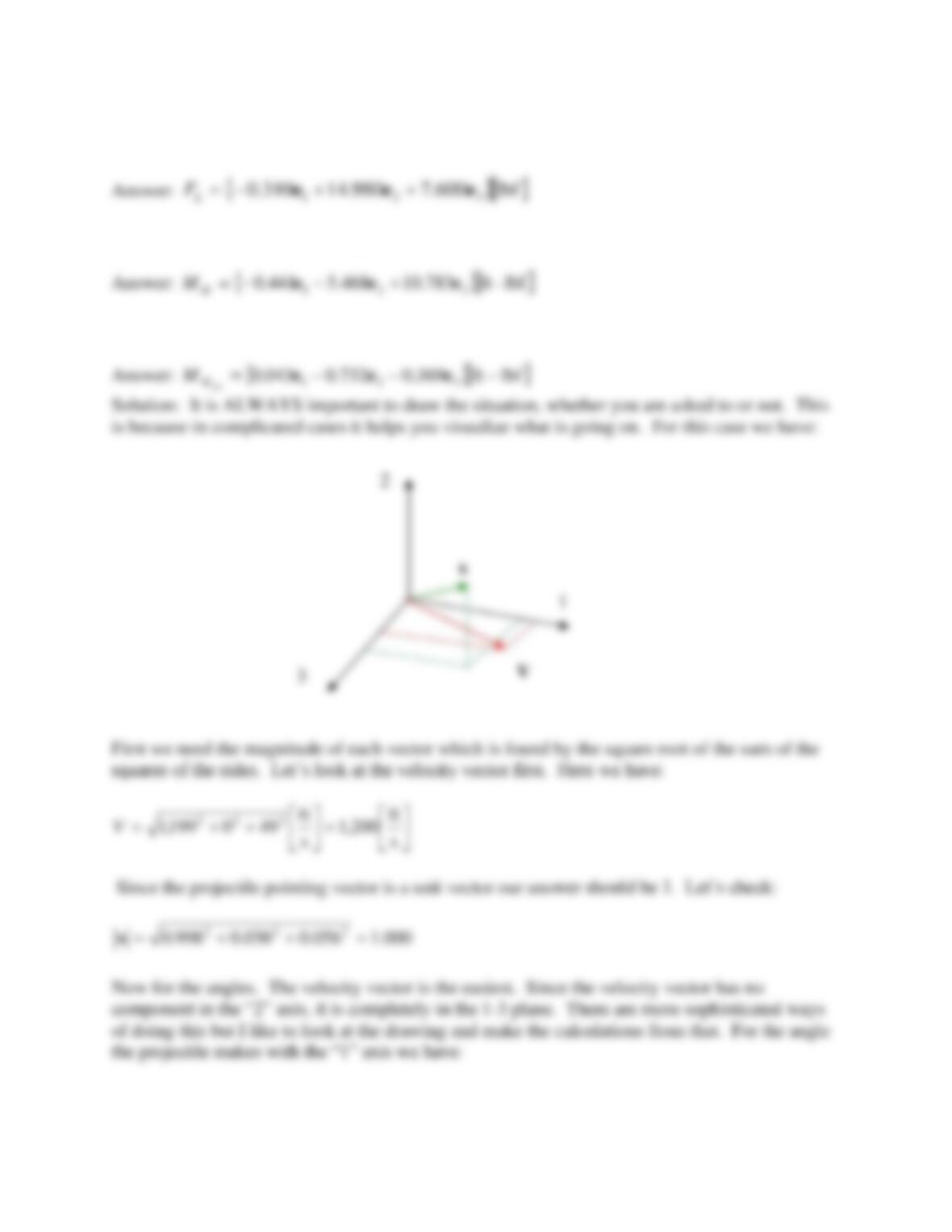
Please answer the following questions:
a) Draw the situation
b) Determine the drag force vector
D
c) Determine the lift force vector
L
d) Determine the overturning moment vector
M
e) Determine the magnus moment vector
34.2
200,1
49
sin 1
1=
=−
V
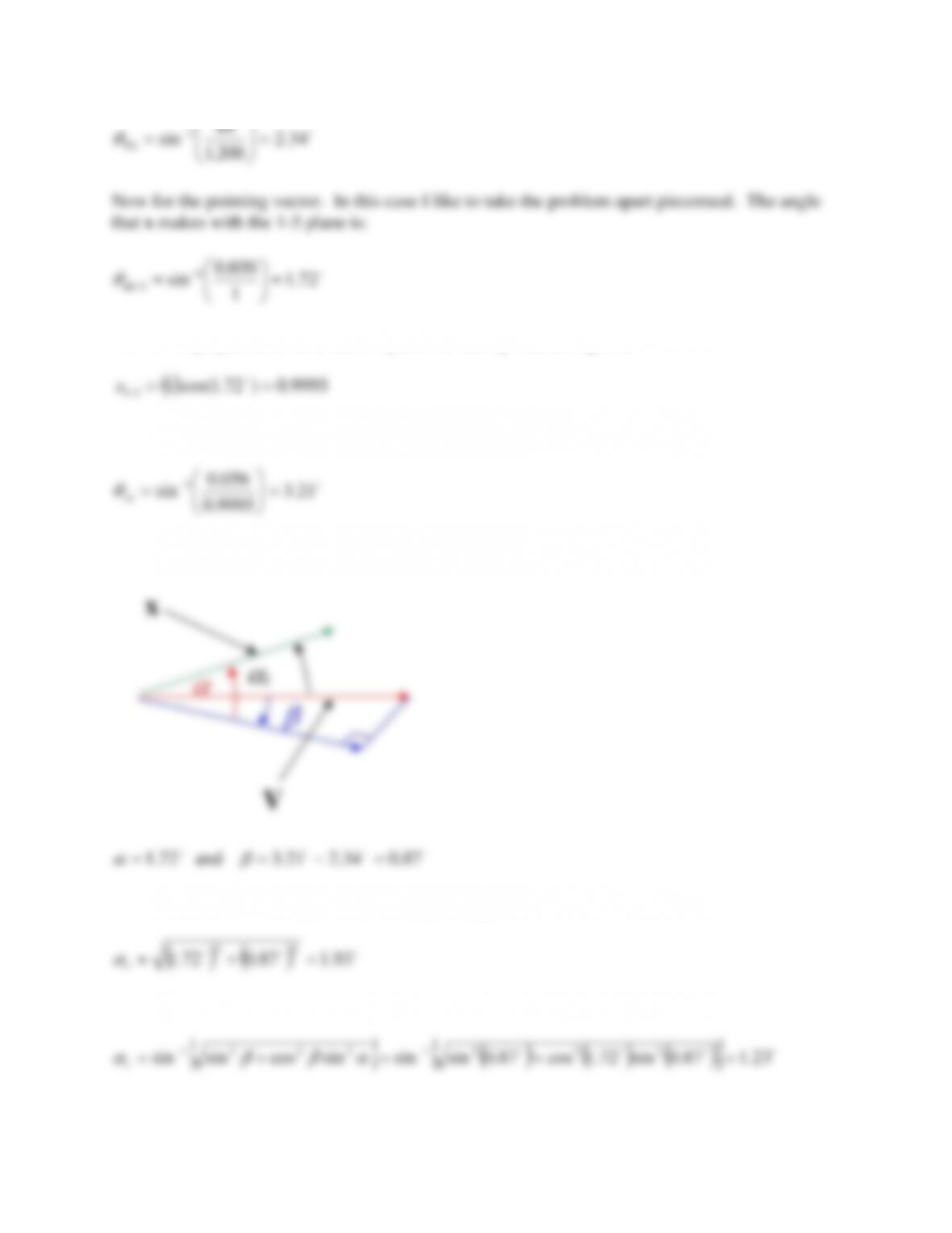
Now for the pointing vector. In this case I like to take the problem apart piecemeal. The angle
that x makes with the 1-3 plane is:
72.1
1
030.0
sin 1
31 =
=−
−x
Now if we project x down to the 1-3 plane we end up with a length of:
31 ==
−
Now to find the angle between the “1” axis and this projection we have:
9995.0
1=
x
So by our flight terminology diagram
Then we could find our approximate total yaw angle as
t
We could have used the exact formula to obtain
t
So you can see there is some difference. For part b.) we were asked for the drag force vector.
We will have to use:
2
For the reference area we shall use the cross sectional area:
Now we solve
D
A couple of things to note here. First ALWAYS put the units in your equations. You can see
that the gc term crept in here but it was not part of the original equation. That’s because the units
MUST work out. You will rarely see the gc term explicitly stated in any of the equations of this
course so be careful. Second, since we were asked for a vector we had better get an answer with
the proper number of components. Third, the negative sign was added since, as a vector, the
drag points opposite to the velocity vector. This was explained in class.
For the lift force vector we need to use
LL SCF2
This involves a cross product. Here we start inside the parentheses first.
−
321
s
97.3524.1847.1
The lift force vector is then calculated from
Does this result surprise you? There is actually a good deal of lift (look at e2) and some drag due
to lift (e3 component) but there is also a large side force. This causes a yaw of repose and is
typically the largest value as the projectile noses over.
Now that we have tackled these let’s do the overturning moment. We’ll use).
056.0030.0998.0
Now the moment is calculated
( ) ( )
( )
( ) ( )
+−−
−
−
=s
ft
97.3524.1847.10.3
s
ft
200,1ft508.0ft203.0
ftlbm
slbf
2.32
1
ft
lbm
052.0
2
1
321
2
2
3eee
M
M
lbf-ft783.10468.5441.0 321 eee +−−=
M
M
All of these parameters change constantly. In this case, the overturning moment wants to turn
the projectile nose up and to the right.
−−
97.3524.1847.1