( ) ( )
( )
( ) ( ) ( )
( )
+
−
=2
22
2
2
22 in25.205.3
in
lbf
193
in25.205.3
1
Cu
( )( ) ( ) ( )( ) ( )
−+−−+−−
=2
222
in
lbf
2
869,100193193869,1
Cu
E
=2
in
lbf
962,1
Cu
E
This shows that the copper will not break up upon exiting the tube – which is a problem, since
the steel is stronger and less dense we expect it to survive too but let’s do the math anyway.
( )
33
2
3ioFe
i
p
Fe
rot rr
r
p−=
( )
( )( )
( ) ( ) ( ) ( ) ( )
( )
−
=3
33
3
2
2
2
in25.205.3
in
lbm
283.0
s–lbf
ft–lbm
2.32
ft
in
12in25.23
s
rad
507
Fe
rot
p
=2
in
lbf
160
Fe
rot
p
−= 2
in
lbf
160
Fe
rr
( ) ( )
( )
+
−
22
2
2
22 in25.205.3
in
lbf
in25.205.3
1
Fe
=2
in
lbf
555,1
Fe
Again we look at von Mises stress
( )( ) ( ) ( )( ) ( )
−+−−+−−
=2
222
in
lbf
2
555,100160160555,1
Fe
E
=2
in
lbf
642,1
Fe
E
Now let’s look at the high zone to finish the problem and see if we can even expect breakup
there. The procedure is the same as before using the higher spin rate. i will just list the
answers.
( )
( )( )
( ) ( ) ( ) ( ) ( )
( )
−
=3
33
3
2
2
2
in25.205.3
in
lbm
316.0
s–lbf
ft–lbm
2.32
ft
in
12in25.23
s
rad
621,1
Cu
rot
p
in
974,1
lbf
( ) ( )
( )
( ) ( ) ( )
( )
+
−
=2
22
2
2
22 in25.205.3
in
lbf
974,1
in25.205.3
1
Cu
=2
in
lbf
137,19
Cu
in
Cu
E
( ) ( )
( )
−
2
2
22 in25.205.3
in
in25.205.3
Fe
=2
in
lbf
927,15
Fe
in
Fe
E
Thus neither design will break apart. The analysis is somewhat conservative in that it is
neglecting the mass of the band that is still left from the rifling and the stress concentrations. It
Problem 9 – An experimental 40 mm gun has an average chamber inner diameter 60 mm. The
weapon is expected to develop a maximum breech pressure of 35,000 psi. If we would like the
weapon to withstand 10,000 cycles at this pressure and given the properties of the steel below
determine the outside diameter of the chamber. Without proper design experience an
interference fit can sometimes be catastrophic. If we were instead to design this chamber out
of two tubes, each at half of this thickness but with the outer tube compressing the inner tube
by 0.002 inches diametrally, what is the maximum pressure the design will accommodate and
still function for the 10,000 cycles?
Assume AISI 4340 steel with a yield strength (SY) of 100,000 psi. The endurance stress (S’n) for
4340 is 0.875SY for the amount of cycles desired. Assume the following factors from our cyclic
loading discussion: CR = 0.93, CG = 0.95 and CS = 0.99. Assume the chamber is open ended. The
Modulus of elasticity and Poisson’s ratio are 30 × 106 psi and 0.3, respectively.
SGRnn CCCSS
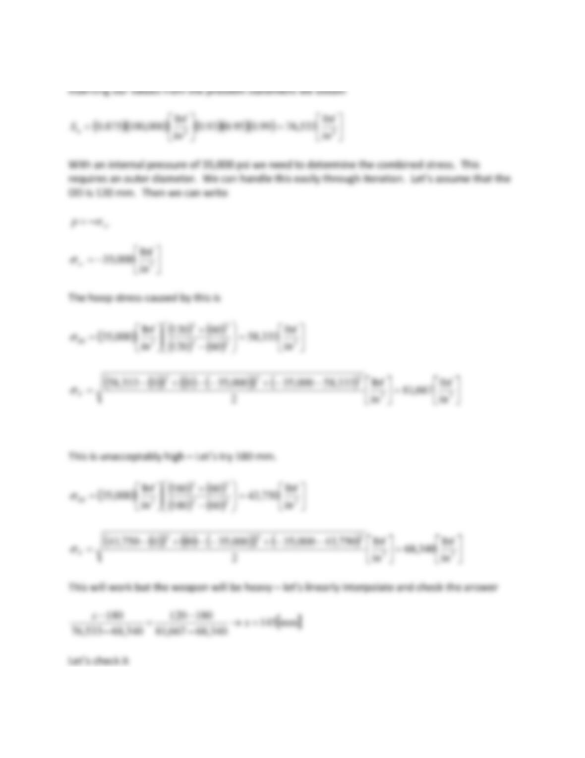
( ) ( ) ( )
( ) ( )
=
−
+
=222
22
2in
lbf
462,49
60145
60145
in
lbf
000,35
( )( ) ( ) ( )( ) ( )
=
−−+−−+−
=22
222
in
lbf
503,73
in
lbf
2
462,49000,35000,3500462,49
E
This is OK it has some extra margin – 135 mm ends up with a stress of 76,034 so we can shave a
little off.
The chamber wall thickness is now
( )
( )
mm5.37
2
mm60mm135 =
−
=t
97.5 mm (3.838 in) and this needs to be compressed 0.002 in. The radial deflection formula is
Plugging in numbers (I like to use diameters which is OK as long as ALL of the dimensions are
diameters) we have
This is also the pressure acting on the outer cylinder. We need to iterate to determine the
initial dimensions of the outer cylinder. Let’s assume the inside diameter is 0.0036 inches
smaller than the equilibrium position of the boundary. Also we shall assume that the outer
diameter is 0.0036 inches smaller than its final dimensions as well. That establishes the
following for the outer tube:
I.D. = 3.838 – 0.002 – 0.0036 = 3.8324 [in]
O.D. = 5.315 – 0.0036 = 5.3114 [in]
Now, let’s expand it with the internal pressure of 8,144 psi. We tailor equation (CD-1) for
internal pressure.
o
Which is consistent with tour earlier assumption. Now we think the assembly will be able to
carry more load but how much? It is here that we need the Lame relations in their full glory.
( ) ( ) ( )
( ) ( )
=
−
+
=222
22
2in
lbf
921,53
832.3311.5
832.3311.5
in
lbf
000,17
( )( ) ( ) ( )( ) ( )
=
−−+−−+−
=22
222
in
lbf
134,64
in
lbf
2
921,53000,17000,1700921,53
E
We keep increasing the pressure until we arrive at the von Mises stress of 76,533 psi. we find
this corresponds to an internal pressure of 20,286 psi. The calculations are
−= 2
in
lbf
286,20
rr
( ) ( ) ( )
( ) ( )
=
−
+
=222
22
2in
lbf
344,64
832.3311.5
832.3311.5
in
lbf
286,20
( )( ) ( ) ( )( ) ( )
=
−−+−−+−
=22
222
in
lbf
530,76
in
lbf
2
344,64286,20286,2000344,64
E
This will expand the inside diameter of the outer tube as follows
( )
( ) ( )( ) ( )( )
( )
( ) ( )
( )
2
22
2
6
2
22
2
in8324.33114.5
in
lbf
1030
in3114.53.018324.33.01
in
lbf
286,20in8324.3
−
++−
=
o
u
in009.0=
o
u
This gives us an inner diameter of
( )
( )
8414.3in009.0in8324.3 =+=+= oifinal udd
( )
( )
( )
( ) ( )
−
+
+−−
−
=oi
oi
oiii
oioiii
iioi
oi
ipp
r
rr
rprp
rrE
r
u2
22
22
22
1
1
(CD–1)
Rearranging we have
( )
( )
( )
( ) ( )
−
+
+−−=
−
oi
oi
oiii
oioiii
oi
iioii pp
r
rr
rprp
r
rrEu
2
22
22
22 1
1
More manipulation is required as follows
( )
( )
( )
( )
( ) ( )
−
−
+
+−=
−
−
oi
oi
oiii
oioiii
oi
iioii pp
r
rr
rprp
r
rrEu
2
22
22
22
1
1
1
( )
( ) ( )
( )
( )
( )
−
+
+
−
+
++
−
−
=
2
22
2
2
22
2
22
1
1
1
1
1
oi
oiii
ii
oi
oiii
oio
oi
iioii
i
r
rr
r
r
rr
rp
r
rrEu
p
( )
( ) ( )
( )
( )
( )
−
+
+
−
+
++
−
−
=
2
2
2
2
2
2
3
22
1
1
1
1
1
1
oi
ii
oi
ii
oi
ii
o
oi
iioii
i
r
r
r
r
r
r
p
r
rrEu
p
2.) Even though there will be a slight taper on the chamber (which must be larger than
the bore diameter for seating purposes) assume, for calculation purposes, that the chamber is
cylindrical at it’s maximum diameter.
3.) The tube is to be steel and assume that the yield strength is 60,000 psi (this accounts
for the effect of cyclic loading). The modulus of elasticity is 29 × 106 psi. Poisson’s ratio is 0.29.
4.) Assume the propellant is either cylindrical or single perforated (and state your
assumption)
5.) Choose from the following propellants
Propellant
Linearized
burn rate, β
(in/s/psi)
Solid
density, δ
(lbm/in3)
Adiabatic
flame
temperature,
T0 (°R)
Propellant
force, λ (ft-
lbf/lbm)
Specific
Heat
ratio, γ
IMR
0.000132
0.0602
5,103
327,000
1.2413
M12
0.000137
0.0600
5,393
362,000
1.2326
Bullseye
0.000316
0.0590
6,804
425,000
1.2523
Red Dot
0.000153
0.0593
5,774
375,000
1.2400
Navy Pyro
0.000135
0.0566
4,477
321,000
1.2454
6.) Assume the cartridge case is brass and use a bi-linear kinematic hardening model
where the brass has a modulus of elasticity of 15106 psi, a local tangent modulus of 13106
psi, a yield stress of 16,000 psi (yield occurs in this material at
= 0.002)
7.) Weight is not a major concern, however you should make the design light enough to
be moved using reasonable test range equipment.
The design is to proceed as follows (not necessarily in the order given):
A.) Interior Ballistics Design
1.) Size the chamber length and diameter
2.) Determine the amount of propellant needed based on your choice of the above
propellants and propellant geometry (make sure it fits in the chamber)
3.) Determine a web thickness for the propellant
4.) Determine the length of the gun
5.) Determine V, pB and x for the projectile at peak pressure
6.) Determine Vc, pBc and xc for the projectile at charge burnout
7.) Determine the muzzle velocity of the projectile
B.) Gun Tube Design
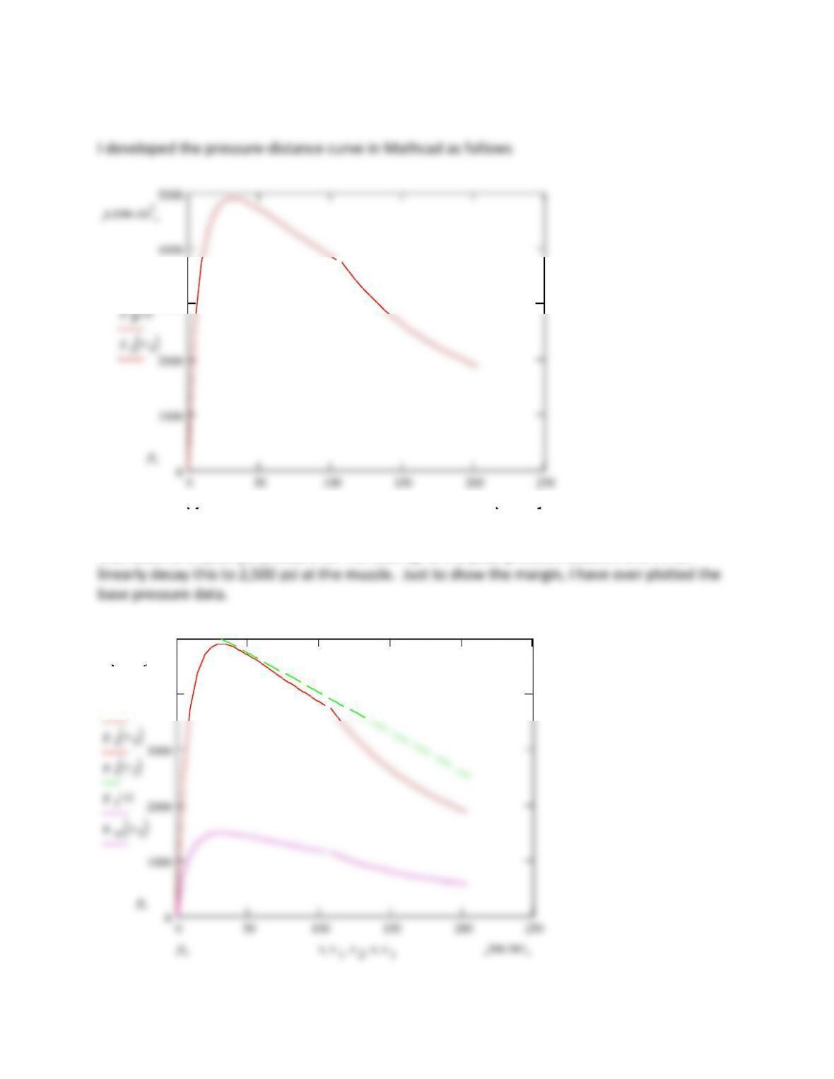
1.) Based on the calculations of part A.) develop a pressure-distance curve to use as
criteria for your gun design
2.) Determine the outside diameter of the gun tube. To keep the design light as
possible use the design rules provided in the text and taper the tube towards the muzzle. If
needed, over the chamber, you may shrink fit cylinders to build up a composite tube
3.) Determine the weight of your gun and comment on if it is reasonable.
C.) Cartridge Case Design
1.) Determine a thickness and tolerance for your cartridge case
2.) Determine the outside diameter and tolerance for the cartridge case
3.) Decide on a tolerance for your chamber inside diameter
Note that for these calculations show that the case may be easily extracted at the limits
of the tolerance.
It is important that you write down all of your assumptions. It is also highly likely that as you
proceed further along with your design you may come upon a situation that requires you to
revisit an assumption you made earlier – this is to be expected and it is part of the design
process.
( )
22
2
in442.0in
4
75.0 ==
c
A
and
( )
( )
in544.16
in
4
75.0
in309.7U
2
2
3
===
c
cA
L
Now let’s start the ballistics calculations. The bore area is
( )
22
2
in196.0in
4
500.0 ==
A
+
1
2
1
2
1
w
c
cw
( )
( )
( )
( )( )
( )
( )( )
( )
( )
( ) ( )
−
−
−
+
+
=
4
2
2
2
2
2
2
2
2
4
2
in
lbf
s
in
000132.0
ftlbm
slbf
2.32
1
lbm
lbfft
000,327lbm22.0lbm048.0
048.02
22.0
1
048.03
22.0
1
in02.0in196.0
M
922.1=M
( )
( )
333
base in654.30in654.3in309.7VUV =−−=−−=
c
i
( ) ( ) ( )
( )
( )
( )( )
( )
( )( )
( )
( )( )
48.01922.1
348.01
048.03
22.0
1
048.02
22.0
1
in3.654
lbm22.0
ft
in
12
lbm
lbfft
000,327
max
−−
−
+
+
−
=epB
=2
in
lbf
903,4
max
B
p
( )
( )
( )
( ) ( )
( )
( )( )
+
−
−
−
=
048.02
22.0
1
ftlbm
slbf
2.32
1
lbm048.0
in
lbf
s
in
000132.0
48.01in50.0in196.0
2
2
2
max
p
V
=s
ft
147,3
max
p
V
Now for the values at charge burnout
( )
( )
in612.18in612.18 922.1 −= exc
in6.108=
c
x
( ) ( ) ( )
( )
( )
( )( )
( )
( )( )
( )
922.1
3
048.03
22.0
1
048.02
22.0
1
in3.654
lbm22.0
ft
in
12
lbm
lbfft
000,327
−
+
+
−
=ep c
B
=2
in
lbf
748,3
c
B
p
( )
( )
( ) ( )
( )
( )( )
+
−
−
=
048.02
22.0
1
ftlbm
slbf
2.32
1
lbm048.0
in
lbf
s
in
000132.0
in50.0in196.0
2
2
2
c
V
=s
ft
048,6
c
V
The muzzle velocity is
B.) Gun tube design
For the internal tube pressure I will assume a pressure-distance profile that is linear below. I
shall assume a 5,000 psi pressure for the tube up to the peak pressure location and I shall
050 100 150 200 250
0
1000
2000
3000
4000
5000
4.899 103
0
pBx( )
pcx1
( )
203.5960 x x 1
3000
4000
5000
5103
pBx( )
pcx1
( )
ptx2
( )
psx( )