CHAPTER 8
Problem 8.1-1: Difference between a propeller and a rotor:
Both are similar, in that they are a set of angled blades that are spun to
Problem 8.1-2: Multirotor configurations with three rotors: Appropriate differential
thrust between the three rotors can provide independent roll and pitch control (two
Problem 8.2-1: In hover, Equation 8.2-4 simplifies by eliminating rotor speed relative
local air (noting we need to keep induced velocity):
When the weight is known, the thrust can estimated by equating thrust and weight
and so the induced velocity can be found
A similar simplification can be applied to induced power (Equation 8.2-11)
Substituting the thrust value from above, we find
2
Problem 8.2-2: In the solution above to Problem 8.2-1, we found that
is a good estimate for the induced velocity in hover. The air density is a property
of the environment, not of the aircraft. This leaves disk area is the only parameter
remaining. So, for single main rotor helicopter, a larger disk area (increasing rotor
radius, R) is expected to help reduce required power, reduce noise, and reduce the
Problem 8.2-3: On a helicopter, a motor or engine provides power to compensate for
both induced and parasite power. The thrust vector can be tilted forward to
generate forward motion. For a gyrocopter, induced power cancels parasite power
in steady state forward flight. Parasite power is not materially different.
However, for induced power to be negative (from Equation 8.2-11)
𝑃𝑖𝑛𝑑𝑢𝑐𝑒𝑑 =𝑇(𝑣𝑖−𝑊𝑃)
Problem 8.2-4: From Equation 8.2-16, we have.
as a definition for propeller pitch. It is necessary to make an assumption about
the pitch of the blade in the neighborhood over the 3/4 point. One reasonable
assumption is ideal twist, of the form
where blade pitch is inversely proportional to radius. Using the 3/4 point as our
reference, this means that
This implies that the slope of blade pitch per change in radius will be
4𝑅)𝑅
which can be used to find a linear twist at the 3/4 point
To enforce the 3/4 point pitch, we need
and so
For a 9×7 propeller, we have R = 9 inches / 2 = 4.5 inches. The pitch is 7
inches. Therefore, by Equation 8.2-17 we could approximate this with linear
twist with
Problem 8.2-5: From Equation 8.2-19, we have the lateral force from a propeller.
If this is an propeller mounted for thrust to be directed along the body x-axis
(forward), then a change of coordinates tells us this will be
Now in terms of body velocity components. This force will generate a yawing
moment if acting in front of or behind the c.g. and acting along the body y-axis.
Approximating this for small angle changes in sideslip,
taking care to correcting account for the sign of the moment generated. This
implies an increment to the non-dimensional directional static stability derivative
2𝜌𝑈0
which is destabilizing if the propeller is the in the front of the c.g. (𝑥𝑝>0) and
stabilizing if behind the c.g.
Problem 8.2-6: The significant effect here is the gyroscopic moment due to the spinning
engine. From Equation 8.2–29, we can simply add the non-negligible inertia of the
𝐌𝐺𝑦𝑟𝑜−𝑃
With inertias and engine RPM, then the gyroscopic moments can be found for any
particular pitch or yaw rate.
Problem 8.3-1: The tip path blade dynamics were derived predominantly by analyzing a
single blade. Other blades on the same rotor would simply lie at a different phase
Problem 8.3-2: Sometimes, the main rotor flapping time constant can be so fast as to be
negligible and/or difficult to simulate due to the system becoming stiff. Starting
with Equations 8.3-15 and 8.3-16,
which is still a function of flybar flapping angles as expected. It is entirely
reasonable to use these approximations for main rotor flapping, while still
modeling the flybar tip path dynamics.
Problem 8.4-1: From Equation 8.4-2, we have
Everything is given in this case except for the mean effective pressure. A
reasonable value for a normally aspirated engine is ten times the atmospheric
pressure (knowing nothing else about the engine).
10
These numbers are similar to the Lycoming O-360 (as something to
compare to), used on aircraft such as the Cessna 172. This engine has a
Problem 8.4-2: When engine power goes through a transmission, the torque is
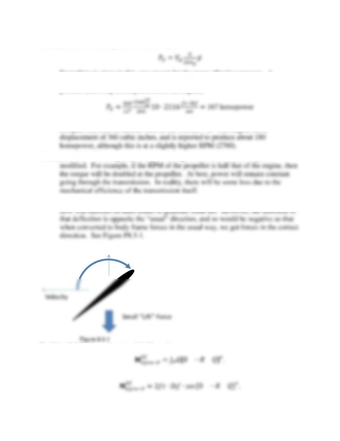
Problem 8.5-1: For a wing with an angle of attack of between 90 and 180 degrees, the
Problem 8.5-2: From Equation 8.2-29, we have
𝐌𝐺𝑦𝑟𝑜−𝑃
𝑏𝑓 =𝐽𝑃𝛺[0 −𝑅 𝑄]𝑇.
To use the numbers we have for this model, the becomes
𝑏𝑓 =2𝑓𝑡∙𝑙𝑏𝑓∙𝑠𝑒𝑐[0 −𝑅 𝑄]𝑇.
This suggests 2 foot-pounds of torque for an angular velocity of 1 radian per
second. At high speed, aerodynamic torques would likely be quite a bit larger.
Problem 8.5-3: The amount of flow twist due to the propeller could be perhaps thought
of as an effective change in the aerodynamic roll rate (∆𝑃𝑝𝑟𝑜𝑝𝑤𝑎𝑠ℎ) for the parts of
There are a variety of methods in the literature to come up with estimates
for this wake rotation. In the spirit of the question, one might just estimate the
angular momentum transfer into the flow due to this torque. A crude estimate
would be:
where 𝐼̇𝑓𝑙𝑜𝑤 is the flow (flux) of inertia of the air going the propeller (similar to the
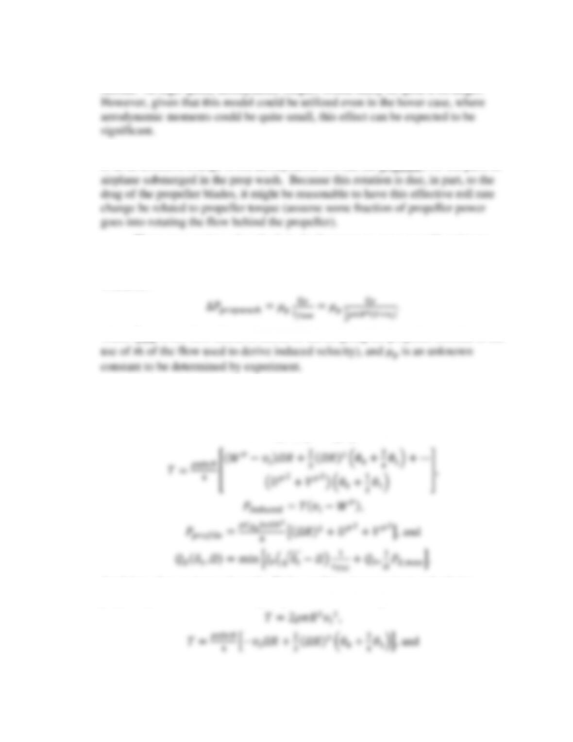
Problem 8.6-1: The maximum static thrust will occur at the maximum possible angular
rate of the motors. Collecting the equations we need, 8.2-4, 8.2-10, 8.2-11, 8.2-
13, and 8.6-1:
𝑇=2𝜌𝐴(𝑉𝑇𝑃+𝑣𝑖)𝑣𝑖,
3(𝛺𝑅)2(𝜃0+3
4𝜃1)+⋯
Applying what we know about the flight condition (not moving) and relating
propeller power to maximum engine power, we can change this to:
which is three equations for three unknowns (𝑇, 𝑣𝑖, and 𝛺). Note this is for a
single propeller.
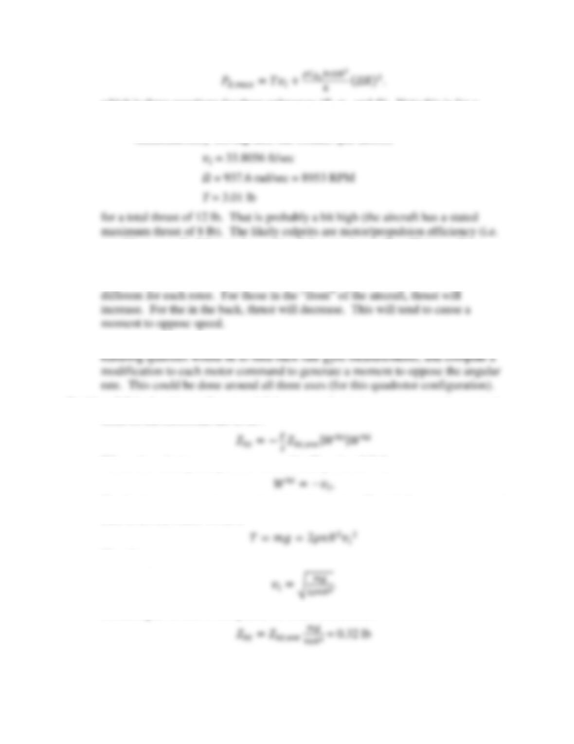
Simultaneously solving this, one obtains (per motor):
not able to use all of the rated power) and the actual propeller efficiency (for
example 𝐶𝑑0 may be optimistic).
Problem 8.6-2: The flow into the propeller (𝑊𝑃 in Equation 8.2-10) will now be
Problem 8.6-3: Perhaps the simplest approach that may yield a design with reasonable
Problem 8.7-1: Looking at Equation 8.7-9, we note that in hover we expect the vertical
force on the horizontal tail to be .
Where the velocity component we need is (Equation 8.7-8)
The final piece we need now is the induced velocity. Thankfully, we are in special
case of hover, where we have
Therefore,
Collecting all of this in one place, we obtain the answer:
Problem 8.7-2: In order to achieve this, an artificial signal can be used to modify the
cyclic pitch commands from the pilot in a manner similar to what a stabilizer bar
does. Looking at Equations 8.3-15 and 8.3-16, we see that the stabilizer bar effect
appears in the same place as pilot input:
To concentrate on the pitch axis (the roll axis could be in a similar manner), we
need to find
Where 𝐾𝑆→𝐶 is now a constant feedback gain in the SAS and 𝑎1𝑆 is the output of a
filter to be designed. If the artificial signal 𝑎1𝑆 behaves in the same way is a real
stabilizer bar, then the real one is not necessary, and this SAS will make the
aircraft behave like it has one. Looking at Equation 8.3-13, we find
which can, in principle be generated in software on an onboard digital SAS as
function of pilot input and rate gyros. The roll coupling term is probably not
helpful, and so the filter implementation could look like
where 𝜏𝑆 and 𝐾𝐶→𝑆 are two final gains the be selected, and 𝑄̃ is measured pitch
angular velocity.