Process Technology Equipment
Chapter 2 Process Drawings and Equipment
Standards
C. Incorrect. The two most common types of drawings are process flow diagrams
(PFDs) and piping and instrumentation diagrams (P&IDs).
D. Correct. The two most common types of drawings are process flow diagrams (PFDs)
and piping and instrumentation diagrams (P&IDs).
Page Reference: 18
Objective: 2.2 Identify the major unit sections in block flow diagrams
Blooms Level: Remember
4. What are basic drawings that use symbols and direction arrows to show the
primary flow of a product through a process?
A. Block flow diagrams
B. Process flow diagrams
C. Utility flow diagrams
D. Electrical diagrams
5. What do symbols represent in a process flow diagram?
A. Power sources required by the process
B. The starting point of the process
C. Sections of a process
D. Major pieces of equipment and piping used in the process
Process Technology Equipment
Chapter 2 Process Drawings and Equipment
Standards
Page 20
6. What are used along with PFDs and P&IDs to identify the major pieces of
equipment, piping, temperatures, pressures at critical points, and the flow of
the process?
A. Schematics
B. Electrical charts
C. Symbology charts
D. Isometrics
7. What additional information is shown on a piping and instrumentation diagram
that is not on a process flow diagram?
A. Pump capacities
B. Control valves
C. Equipment symbols
D. Equipment numbers
Page Reference: 20
Process Technology Equipment
Chapter 2 Process Drawings and Equipment
Standards
Process Technology Equipment
Chapter 2 Process Drawings and Equipment
Standards
Page 22
10. What drawings show objects as they would appear in a three-dimensional
drawing?
A. Plot plans
B. Isometric drawings
C. Electrical schematics
D. Process flow diagrams
11. What is another name for plot plan diagrams?
A. Elevation diagrams
B. Logic diagrams
C. Process drawings
D. Equipment location drawings
12. What type of drawing is the screen display used by control room operators to
control unit operations?
A. Elevation diagram
B. Process schematic
C. Loop diagram
D. Logic diagram
Process Technology Equipment
Chapter 2 Process Drawings and Equipment
Standards
13. What type of drawing shows the sequential steps within the computer or
safety system?
A. Elevation diagram
B. Process schematic
C. Loop diagram
D. Logic diagram
14. What are simple illustrations used to identify types of equipment?
A. Legend
B. Symbols
C. Title block
D. Application block
Process Technology Equipment
Chapter 2 Process Drawings and Equipment
Standards
Page 24
15. What is the main part of a drawing that contains symbols and defines
elements such as relative position, types of materials, equipment descriptions,
and functions?
A. Legend
B. Symbols
C. Title block
D. Application block
16. How are hydraulic actuators operated?
A. By hand wheels
B. By an air signal
C. By an electrical motor
D. By fluid pressure
Process Technology Equipment
Chapter 2 Process Drawings and Equipment
Standards
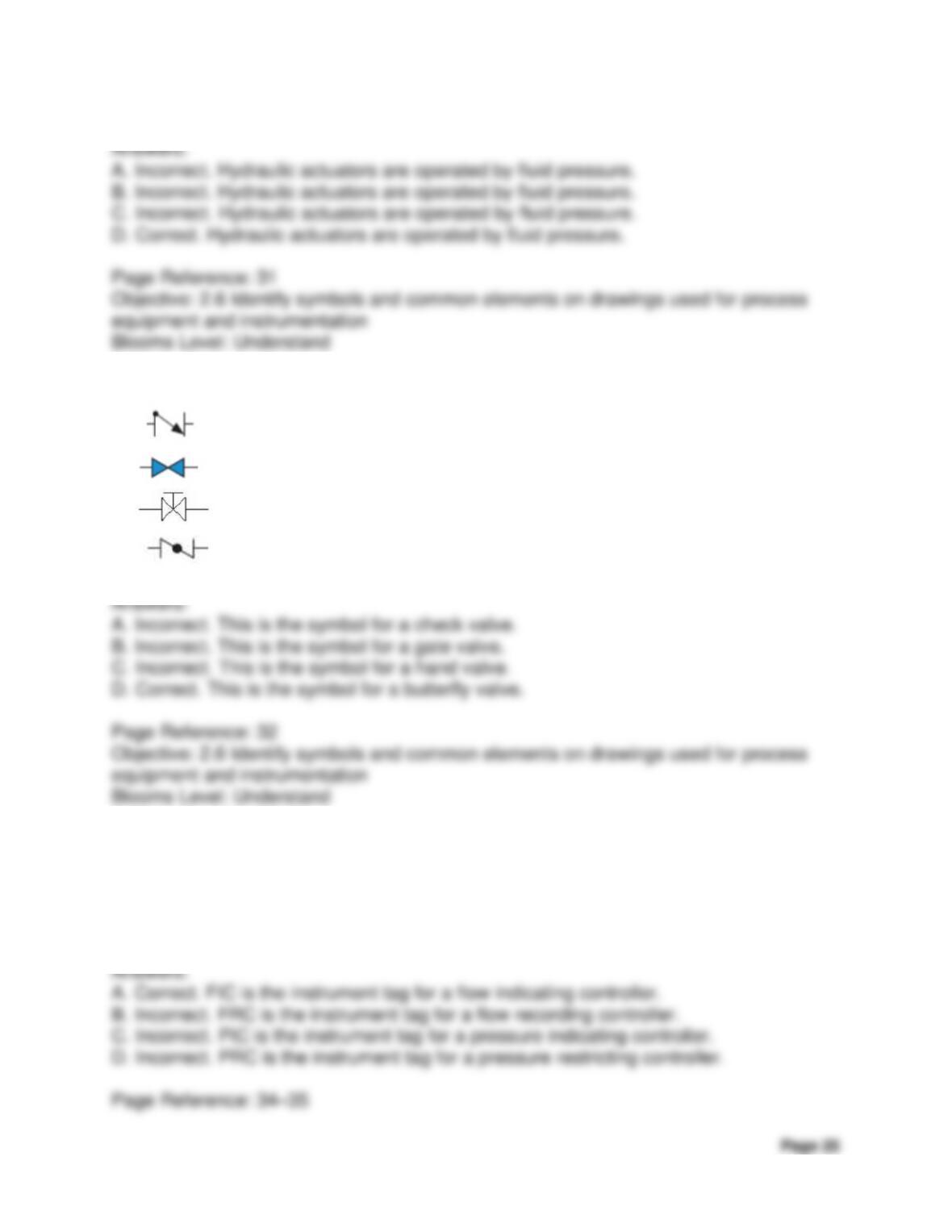
17. Which of the following is an example of a butterfly valve symbol?
A.
B.
C.
D.
18. What would be the instrument tag for a flow indicating controller?
A. FIC
B. FRC
C. PIC
D. PRC
Process Technology Equipment
Chapter 2 Process Drawings and Equipment
Standards
Process Technology Equipment
Chapter 2 Process Drawings and Equipment
Standards
Page 27
21. What organization specifies requirements and standards for pressure vessels,
piping, and their fabrication?
A. The National Electric Code (NEC)
B. The Occupational Safety and Health Administration (OSHA)
C. The American Petroleum Institute (API)
D. The American Society of Mechanical Engineers (ASME)
Clicker Questions
(Note to Instructor: If you have clicker capability in your institution, you may want to
include some of these questions as appropriate. Or perhaps you just want to use them
as a way to check the students’ understanding of the content.)
1. What are simple drawings that show a general overview of a process and
contain few specifics?
A. Block flow diagrams
B. Process flow diagrams
C. Utility flow diagrams
D. Electrical diagrams
Process Technology Equipment
Chapter 2 Process Drawings and Equipment
Standards
Page 28
2. What type of diagrams help process technicians understand power
transmission and how it relates to the process?
A. Block flow diagrams
B. Process flow diagrams
C. Utility flow diagrams
D. Electrical diagrams
3. What drawings may be useful to new process technicians as they learn to
identify equipment and understand its inner workings?
A. Block flow diagrams
B. Process flow diagrams
C. Isometric drawings
D. Electrical diagrams
Process Technology Equipment
Chapter 2 Process Drawings and Equipment
Standards
Page 29
4. How are pneumatic actuators operated?
A. By hand wheels
B. By levers
C. By an air signal
D. By an electrical motor
5. What organization is a trade association that represents the oil and gas
industry?
A. International Society of Automation (ISA)
B. The American National Standards Institute (ANSI)
C. The American Petroleum Institute (API)
D. The American Society of Mechanical Engineers (ASME)

Process Technology Equipment
Chapter 2 Process Drawings and Equipment
Standards
Page 30
APPENDIX, Chapter 2
Table of Contents
Contents
Page
Checking Your Knowledge Questions and
Answers
31
Process Technology Equipment
Chapter 2 Process Drawings and Equipment
Standards
Checking Your Knowledge Answer Key
1. Define the following terms:
a. Application block
b. Legend
c. Symbol
d. Title block
e. Block flow diagram (BFD)
f. Electrical diagram
g. Isometric drawing
h. Piping and instrumentation diagram (P&ID)
i. Plot plan
j. Process flow diagram (PFD)
k. Process schematic
l. Utility flow diagram (UFD)
Process Technology Equipment
Chapter 2 Process Drawings and Equipment
Standards
Page 32
2. Which drawing provides a general overview of the process and contains few
specifics?
a. PFD
b. BFD
c. P&ID
d. UFD
3. Process Flow Diagrams are typically drawn from the ______________.
4. Which of the following items are located on a Process Flow Diagram? (Select
all that apply.)
a. Pump capacities
Process Technology Equipment
Chapter 2 Process Drawings and Equipment
Standards
b. Equipment symbols
c. Equipment designations
d. Cooler symbols
5. (True or False) UFDs provide process technicians a PFD-type view of the
instrumentation used for a process.
6. Which of the following are included in a process drawing? (Select all that
apply.)
a. Legend
b. Title block
c. Application block
d. Electrical codes
Process Technology Equipment
Chapter 2 Process Drawings and Equipment
Standards
Page 34
7. (True or False) A balloon is an instrumentation symbol that is commonly used
to represent the function of different instruments.
8. On an FIC ISA tag, what does the first letter “F” stand for?
a. Frequency
b. Flow
c. Force
d. Function
9. Which society develops standards for automation, instrumentation, control,
and measurement symbols?
a. API
b. NFPA
c. ISA
d. ASME
Answers:
Process Technology Equipment
Chapter 2 Process Drawings and Equipment
Standards
Process Technology Equipment
Chapter 2 Process Drawings and Equipment
Standards
Page 36
13. What type of diagram shows all components and connections between
instrumentation and the control room?
a. Elevation diagram
b. Process schematics
c. Loop diagram
d. Logic diagram
14. The National Fire Protection Agency established the _______, specifies
practices that promote the safe installation of electrical wiring and equipment.