1
Chapter 10
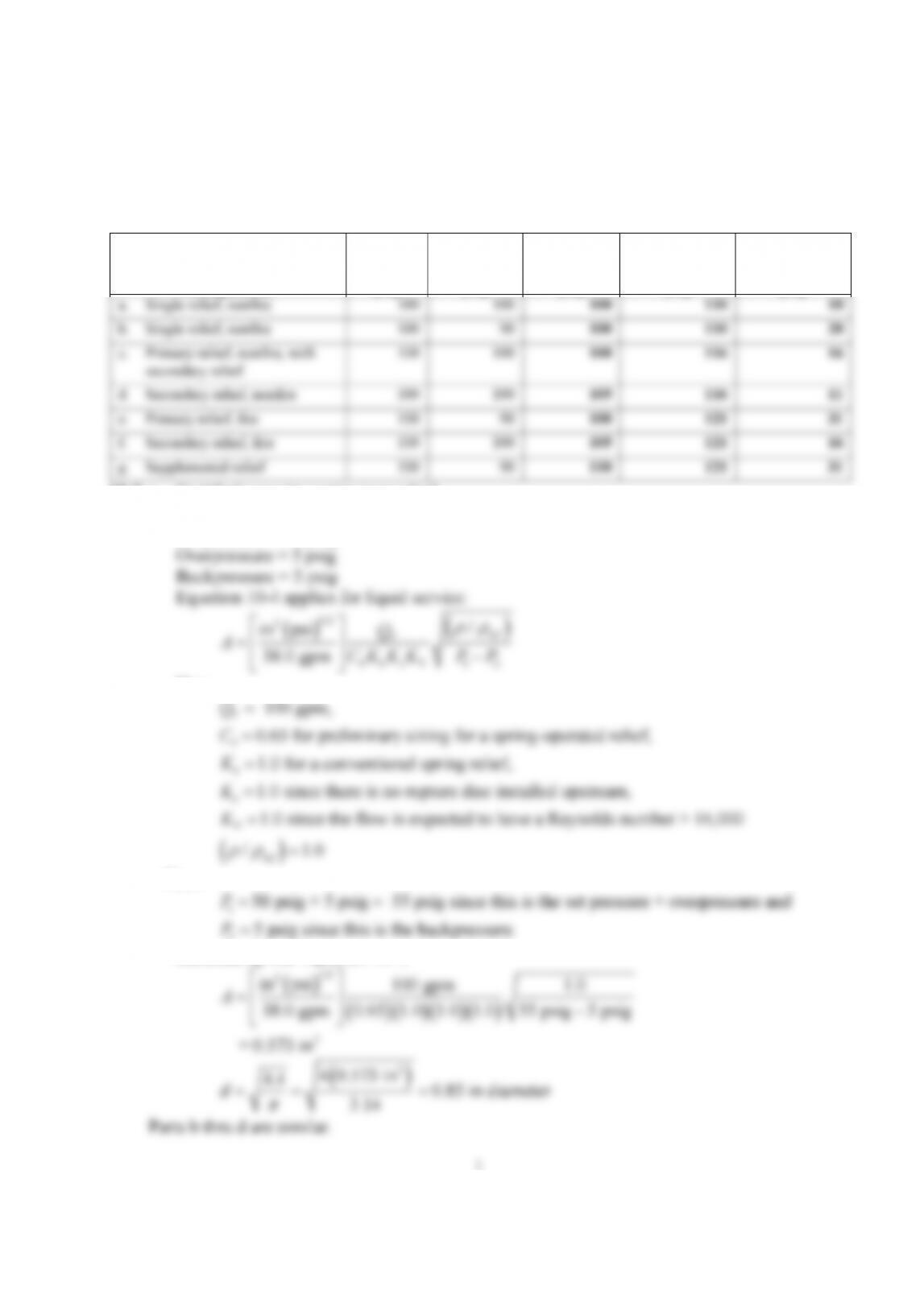
10-1.
Relief
Configuration
MAWP
psig
Set
Pressure
psig
Maximum
Set
Pressure
psig
Maximum
Accumulated
Pressure
psig
Allowable
Overpressure
psig
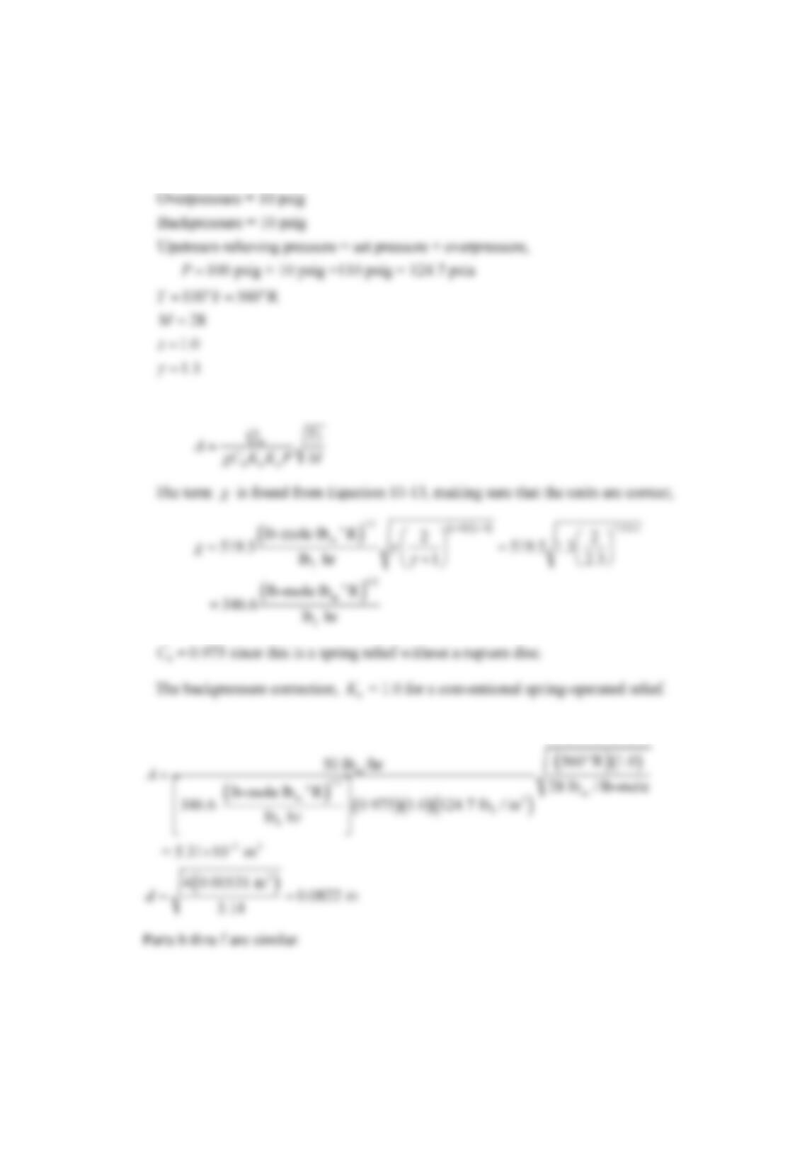
10-2. a. Certified capacity spring-type relief.
Liquid flow = 100 gpm
Set pressure = 50 psig
0 b c V 1 2
38.0 gpm
C K K K P P
Here:
0
b
c
V
100 gpm,
0.65 for preliminary sizing for a spring-operated relief,
1.0 for a conventional spring relief,
1.0 since there is no rupture disc installed upstream,
1.0 since the flow is expect
V
Q
C
K
K
K
ed to have a Reynolds number > 16,000
/ 1.0
ref
Then
2
Substituting into Equation 10-4:
1/2
2
in psi 100 gpm 1.0
A
2
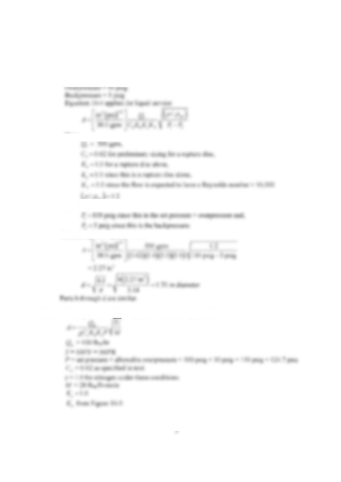
10-3. a. Spring operated relief in vapor service – assume a conventional spring relief.
m
Required mass flow, 50 lb / hr
m
Q
1.0
1.3
z
Equation 10-12 now applies:
m
Q
Tz
b
Substituting, being careful of units!
o
m
1/2
om
560 R 1.0
50 lb /hr
28 lb / lb-mole
A
10-4. a. Rupture disc in liquid service.
Liquid flow = 500 gpm
Set pressure = 100 psig
0 b c V 1 2
38.0 gpm
C K K K P P
Here:
0
b
500 gpm,
0.62 for preliminary sizing for a rupture disc,
1.0 for a rupture disc alone,
V
Q
C
K
ref
Then
2
110 psig since this is the set pressure
+ overpressure and,
P
Substituting into Equation 10-4:
1/2
2
in psi 500 gpm 1.2
A
10-5. a. Use Equation 10-12 for vapor service thru a rupture disk.
m
Q
o
C
K
Q Tz
b
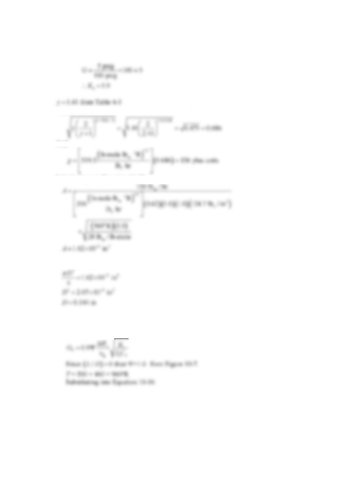
4
5 psig
100 5
G
Then:
1 / 1 2.41/0.41
2 2
And
1/2
m
f
lb-mole lb R
lb hr
o
Substituting into Equation 10-12:
m
1/2
m
2 2
100 lb / hr
1.62 10 in
o
A
A
The relief diameter is:
0.144 in
D
Parts b thru d are similar.
10-6. a. Use Equation 10-16:
v c
H g
5
m f
T3
m
130 BTU/lb 778 ft lb / BTU
0.9 1.0 1.4 0.02 ft / lb
G
m
0.638 BTU/lb s
This is the heat generation rate in the reactor.
Now apply Equation 10-20
o
2
1/2
1/2
v
T V
o fg
m m
10,000 lb 0.638 BTU/lb s
m q
A
V H
G C T
m v
10-7. The original problem as presented in the 1st printing of the 4th edition is confusing and
difficult to work. The revised problem is shown below:
Determine the deflagration vent size for the following structures.
Vapors a b c d
Internal area of structure: 1000 ft2 1000 ft2 300 m2 300 m2
Dusts e f g h
Volume of structure: 1000 ft3 1000 ft3 30 m3 30 m3
c. Use Equation 10-23 with Equation 10-25 to estimate the vent area required.
Start with Equation 10-25:
u
Substituting into Equation 10-23:
2 1/2
2
v
red
300 m 0.00893 bar
12 m
0.05 bar
s
A C
AP
Parts a, b and d are the same. For English units need to convert to correct units for fixed
unit equation.
g. Apply Equation 10-29 – being careful to use the correct unit:
4 3/4 4/3 max
P
unit equation
10-8. Use Equation 10-42:
v a
p
C
Here:
o
P
3
2
2
a
0.58 kcal/kg C
791 kg/m
300 m
1000 J/s m K
300 K
550 K
C
A
U
T
T
5 o 1
Substituting into Equation 10-42:
5 o 1
112 10 C
10-9.
This is a complex problem with many possible approaches. First, let’s state some facts about
this situation:
a. The rate of energy discharge thru the relief device must match the heat input from the
burner in all cases.
8
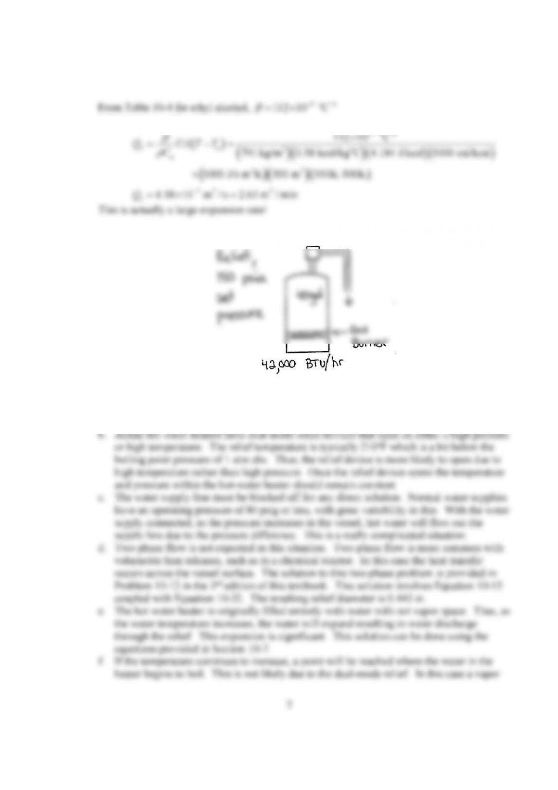
10-10.
In this casee a vapor space will occur after the relieving starts. Thus, it will be vapor
discharge. Equation 10-12 then applies to size the vapor relief size.
From the steam tables at 50oF:
3
f m
p m
1/ 62.41 lb / ft
1 BTU/lb F
v
C
From Example 10-10, the thermal expansion coefficient at 50oF is 5 o
3.47 10 / F
.
The surface area is the cylinder (excluding the ends) is:
2
Assume only the top half of the vessel is exposed to the sun, and not the ends. Then,
2 2
Substituting into Equation 10-10:
o
5 o 2 o 2
v a 3 o
pm m
2 3 2
3.47 10 / F 50 BTU/hr-ft – F 100 50 F 62.8 ft
8.73 10 ft / hr 0.653 gal/hr 1.09 10 gpm
Q UA T T
This is a very small expansion.
For fire exposure, assume that the vessel is horizontal. The surface area of the ends must
be added.
2
2 2
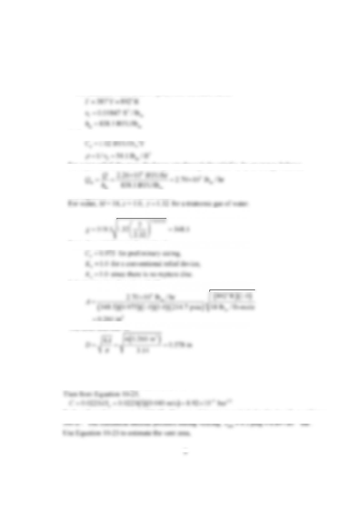
The MAWP of the vessel is 200 psig = 214.7 psia. Use this as the set pressure for the
relief and also the pressure inside the vessel during the relief (with no overpressure). The
water will boil at this pressure.
For saturated water at 214.7 psia, from the steam tables:
0.01847 ft / lb
o o
3
f m
fg m
387 F 892 R
838.1 BTU/lb
T
h
And,
1/ 54.1 lb / ft
o
p m
f m
1.02 BTU/lb F
C
For vapor relief, the mass discharge rate through the relief is, by an energy balance,
m m
fg m
838.1 BTU/lb
Use Equation 10-12 to size the relief.
Then from Equation 10-13,
From the guidelines in the textbook:
1.0
Substituting into Equation 10-12:
o
3
m
m
2
892 R 1.0
2.70 10 lb / hr
348.5 0.975 1.0 1.0 214.7 psia 18 lb / lb-mole
0.260 in
A
The relief diameter is:
2
4 0.260 in
4
0.578 in
3.14
A
D
10-11. The vent area is estimated using Equations 10-25 and 10-23.
For methane from Table 10-2, u
40 cm/s 0.040 m/s
S .
Assume no turbulent augmentation, then
1
.
u
Each wall on the structure is 100 ft2. The area of the structure includes the 4 walls + ceiling =
2 4 1/2
2
s
500 ft 8.92 10 bar
A C
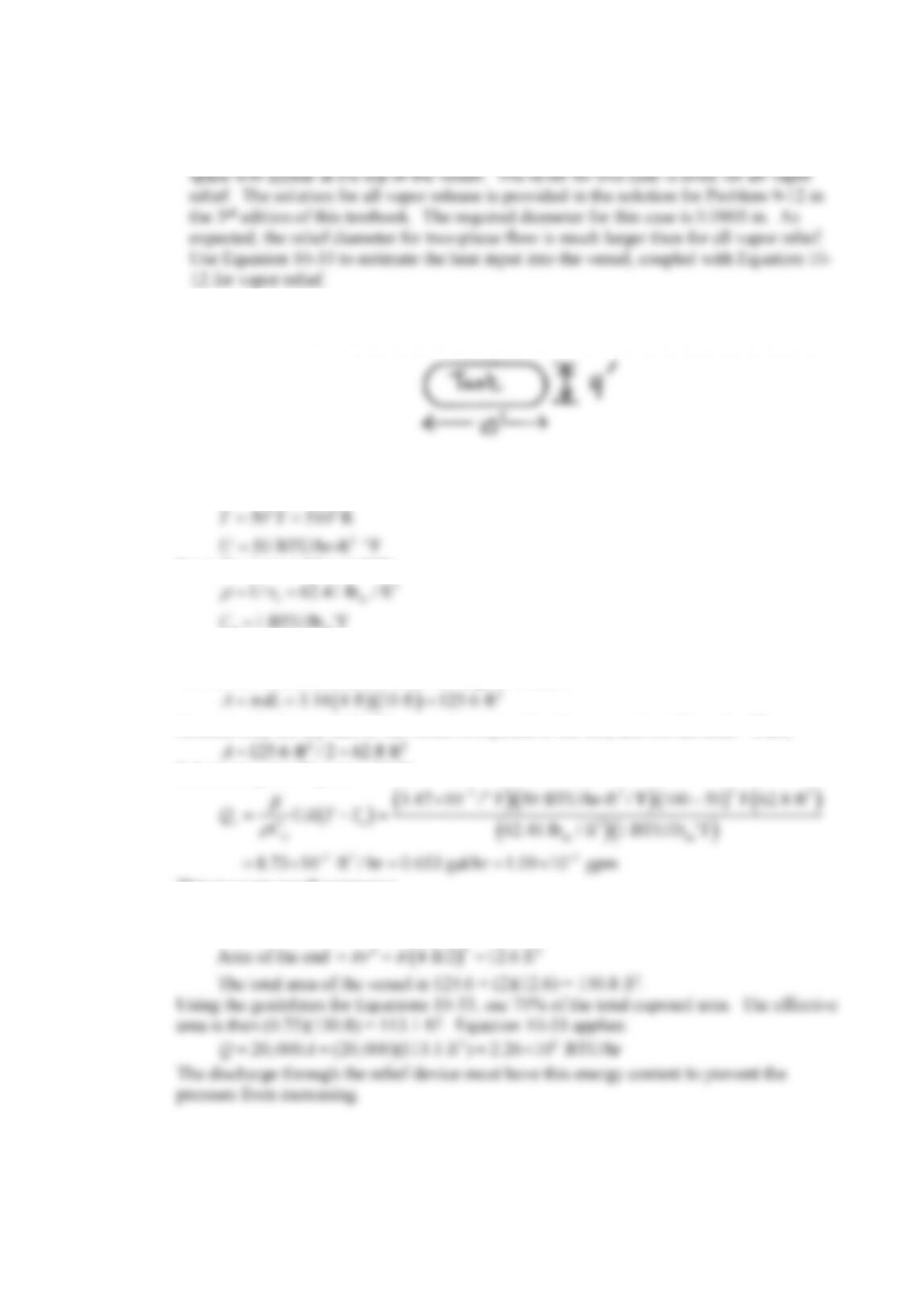
10-12. This is almost identical to the second part of Problem 10-10, but in metric units. Use
Equation 10-12 with Equation 10-14.
Total surface area of vessel =
2 6.28 0.5 m 3.14 1 m 3 m 11.0 m 118 ft
2
2 2 2
From the guidelines with Equation 10-30, take 75% of this surface area,
From Equation 10-33 – being careful of units:
2 6
20,000 20,000 88.9 ft 1.78 10 BTU/hr 520 kJ/s
Q A
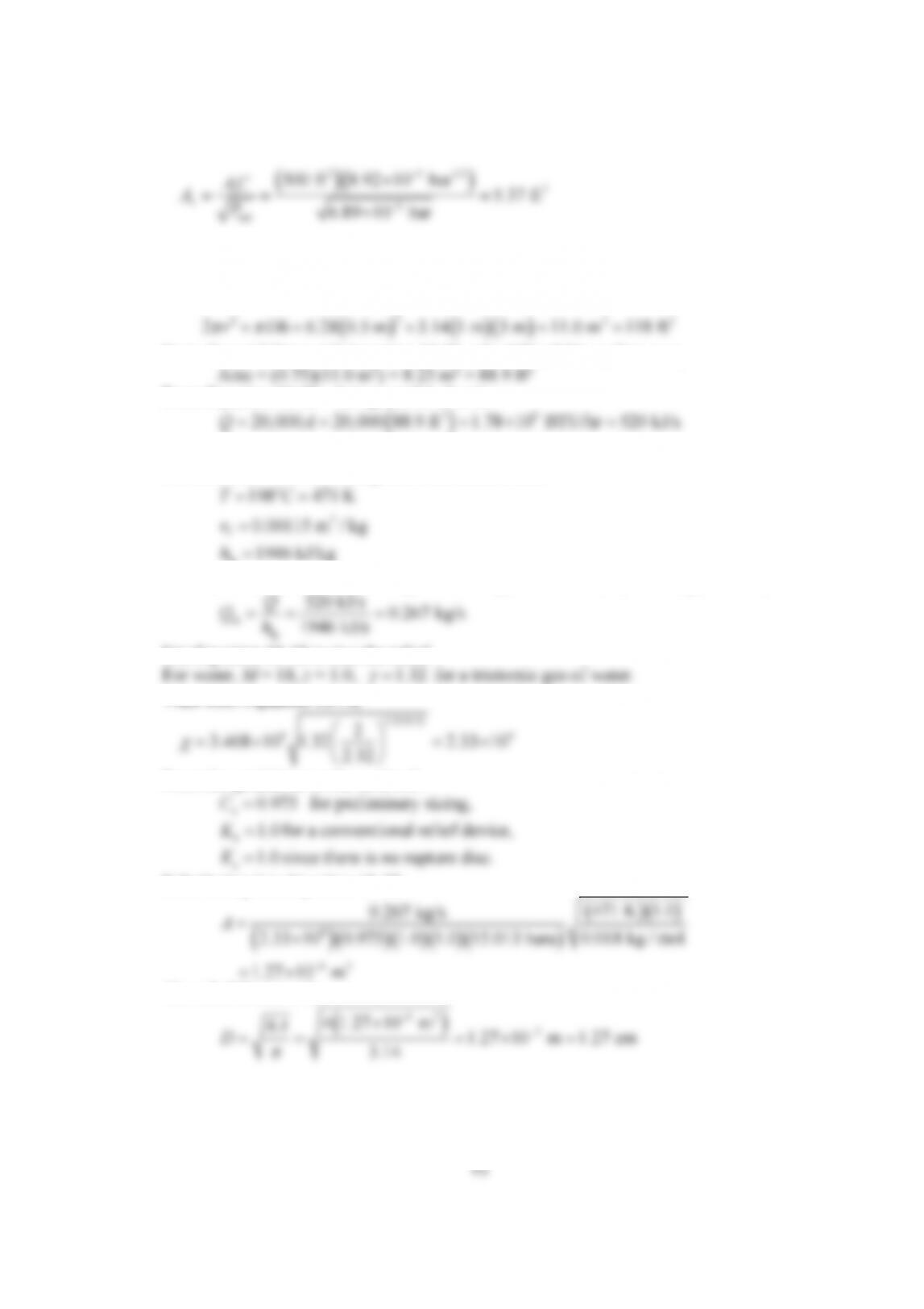
Assume no overpressure and a set point equal to the MAWP of 14 barg = 15.013 bara.
For saturated water at 14 barg, from the steam tables:
0.00115 m / kg
o
3
fg
198 C 471 K
1946 kJ/kg
T
h
For vapor relief, the mass discharge rate through the relief is, by an energy balance,
fg
520 kJ/s
1946 kJ/s
Q
Use Equation 10-12 to size the relief.
Then from Equation 10-14,
2.32/0.32
4 4
2
From the guidelines in the textbook:
c
Substituting into Equation 10-12:
0.018 kg / mol
4
4 2
471 K 1.0
0.267 kg/s
1.27 10 m
A
The relief diameter is:
4 2
2
4 1.27 10 m
4
3.14
A
Problems and Solutions for Chapter 11
Problem 11-1.
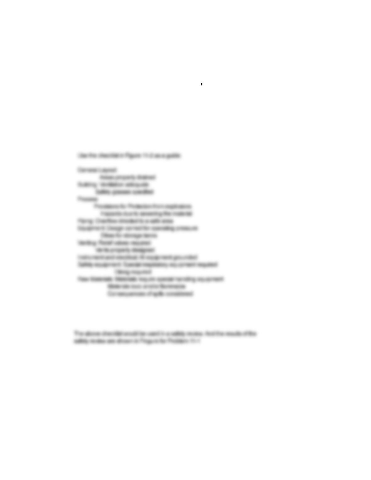
In a pilot plant, toluene is transferred from a drum to an open bucket. Develop a checklist for this procedure.
Include inerting / purging, ventilation, grounding and bonding and any other safety procedures.
Solution for Problem 11-1
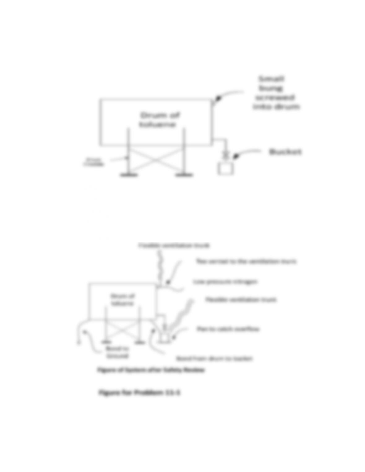
Small
bung
screwed
intodrum
FigureofSystemafterSafetyReview
FigureforProblem11‐1
Bondto
Ground Bondfromdrumtobucket
Problem 11-2. Perform a HAZOP on the reactor in Example 11-2. The reaction is exothermic, so
cooling coils removes the heat of reaction. The temperature is controlled by controlling the flow of
cooling water. Use as a study node the cooling coil (process parameters: flow and temperature) and
the stirrer (process parameter: agitation).
Solution for Problem 11-2
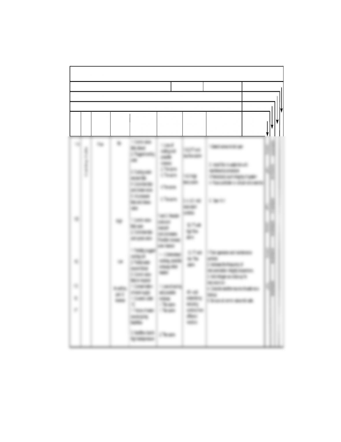
Hazards and Operability Review
Project Name: Date: 9/1/2018 Page of 1 of 2 Completed
No action:
Reply Date
Assigned to:
Process: Reactor of Example 11–2
Section: Reactor Shown in Example 11-2
Item Study
Node
Process
Parameters
Possible Causes Possible
Consequences Safeguards Recommendations
Deviations
(Guide
Words)
Example 11-2
source giving
backflow
2. Backflow due to
high backpressure
different
vendors
2. The same
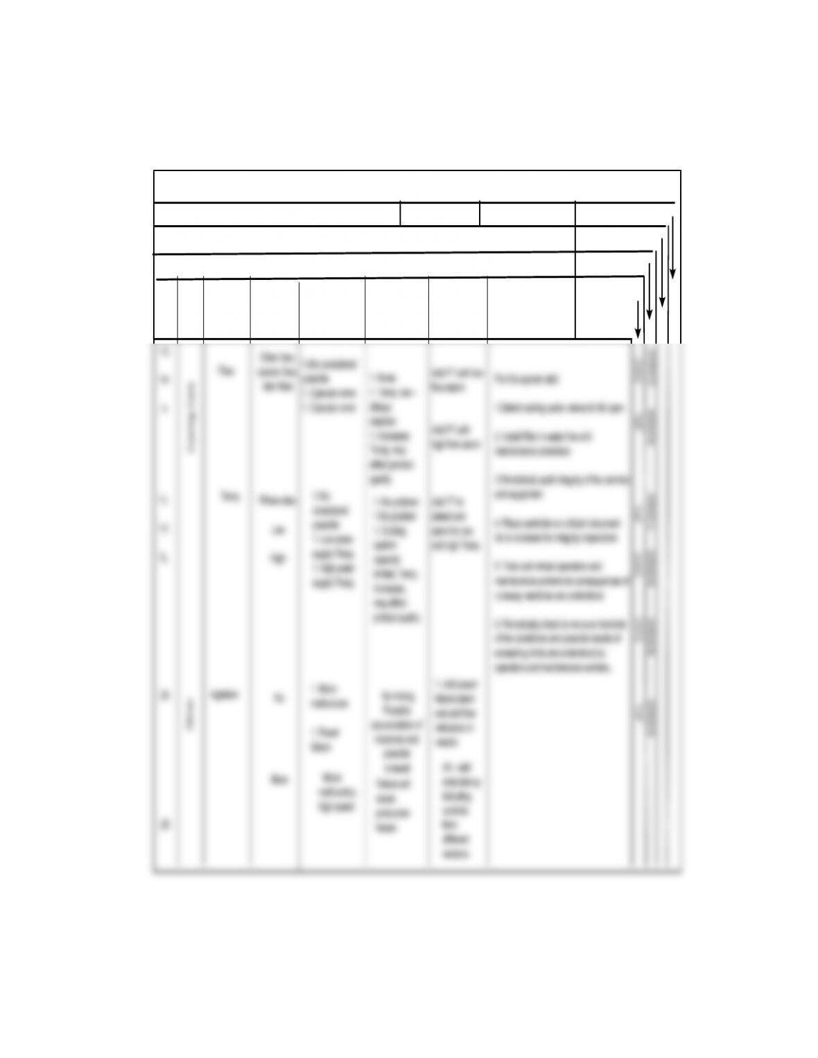
Hazards and Operability Review
Project Name: Date: 9/1/2018 Page of 2 of 2 Completed
No action:
Reply Date
Assigned to:
Process: React or of Example 11–2
Section: Reactor Shown in Example 11-2
Item Study
Node
Process
Parameters
Possible Causes Possible
Consequences Safeguards Recommendations
Deviations
(Guide
Words)
Example 11-2
Flow 1. None
1. Temp. low –
delays
reaction
1. Increases
For this system add:
1.Select cooling water valves to fail open
2. Install filter in water line with
1.Not considered
possible
1. Operator error.
1. O perator error
DAC
JFL
4/2020
Add FT with low
flow alarm
Add FT with
high flow alarm
different
vendors
1G
1H
1I
Other than,
sooner than,
later than
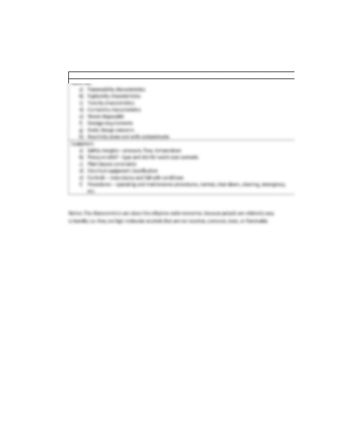
Problem 11-3. If the monomer in Example 11- 2 is ethylene oxide, identify the hazards by developing
a list of material hazards and a list of process hazards.
Solution for Problem 11-3
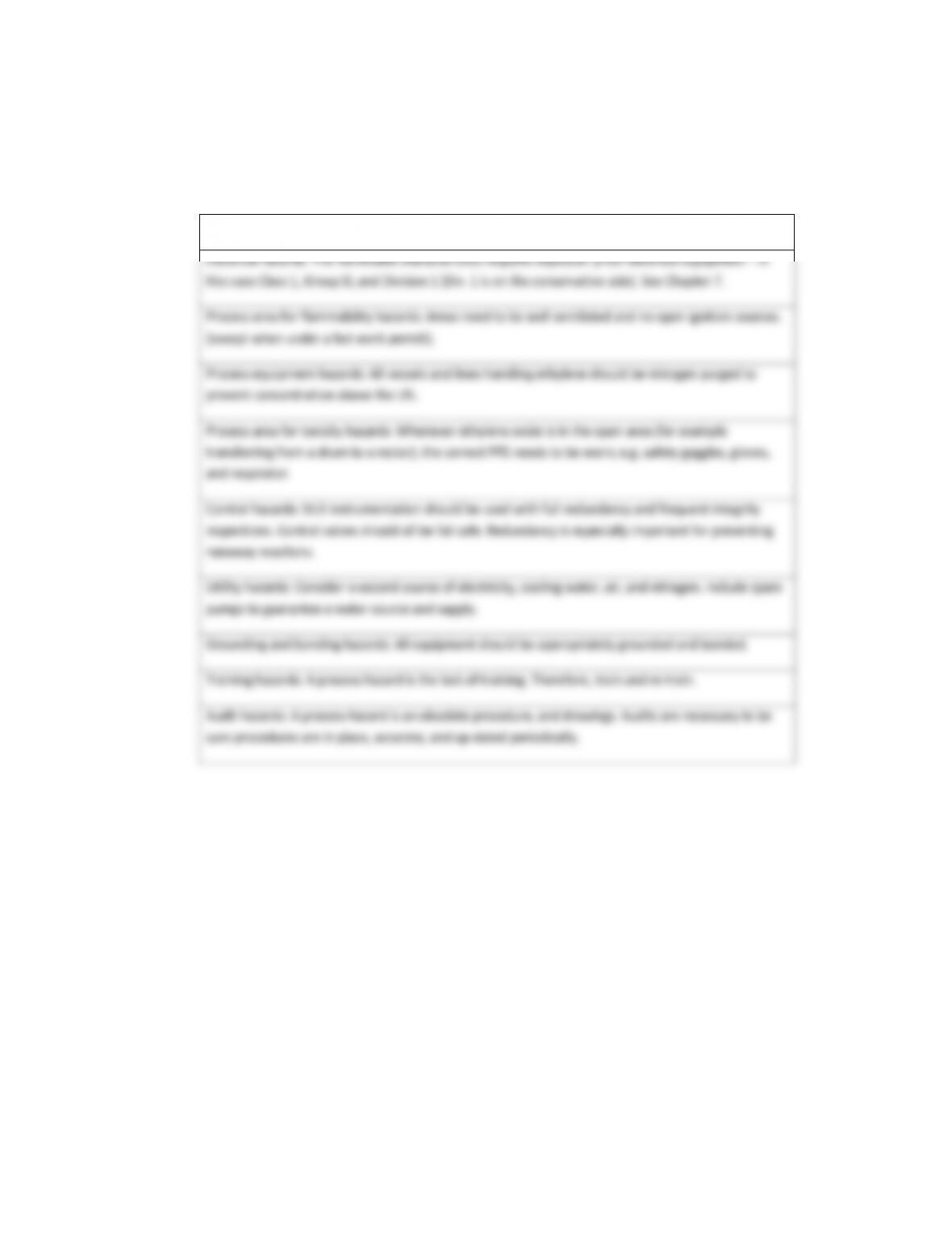
Notice:ThefollowinglistisgeneratedwithexperiencedpersonnelandadocumentliketheHAZOPs
helps.Belowarelistedtheprocesshazards,andsomeactionstosafelyoperateinthisenvironment.
Listofprocesshazards
Problem 11-4. The concept of “fail safe” is used to specify the position (fail closed or fail open) of all
process valves in the event of a utility failure. The specified fail open or fail closed puts the process in
a safe mode of operation. Specify the proper fail-safe position for the following situations:
a) A process valve regulates the flow of steam that heats a solvent in a heat exchanger.
b) A valve controls the flow of a reactant (exothermic reaction) to a reactor.
c) A valve controls the flow of a reactant (endothermic reaction) to a reactor.
d) A valve controls the flow of natural gas to a furnace.
e) A remote valve is connected to a storage tank drain line.
f) A remote valve is connected to a fill line to a storage tank.
g) A valve controls the combustion air to a furnace.
h) A valve releases excessive pressures in a steam header.
Solution for Problem 11-4
Problem 11-5. Conduct a safety review for the design of the system described in Example
11-2. This reactor is used to polymerize ethylene oxide to form polyols.
Solution for Problem 11-5
TablesforProblem11‐5
ChecklistforaSafetyReviewfortheDesignoftheReactorshowninExample11‐2