441
Ans.
NA=15.6 kN
Cx=0
Cy=38.4 kN
MC=14.4 kN #m
442
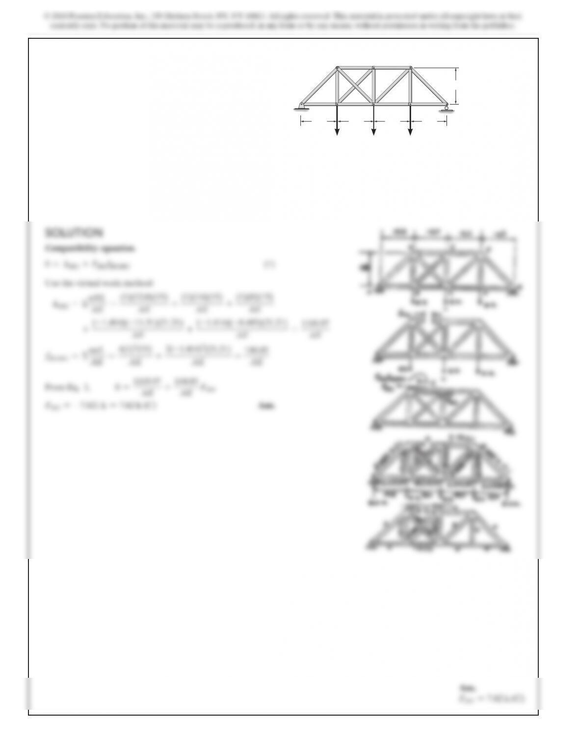
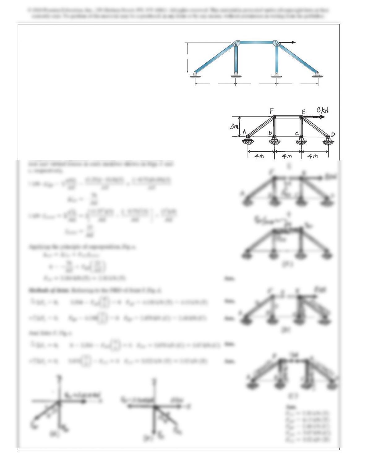
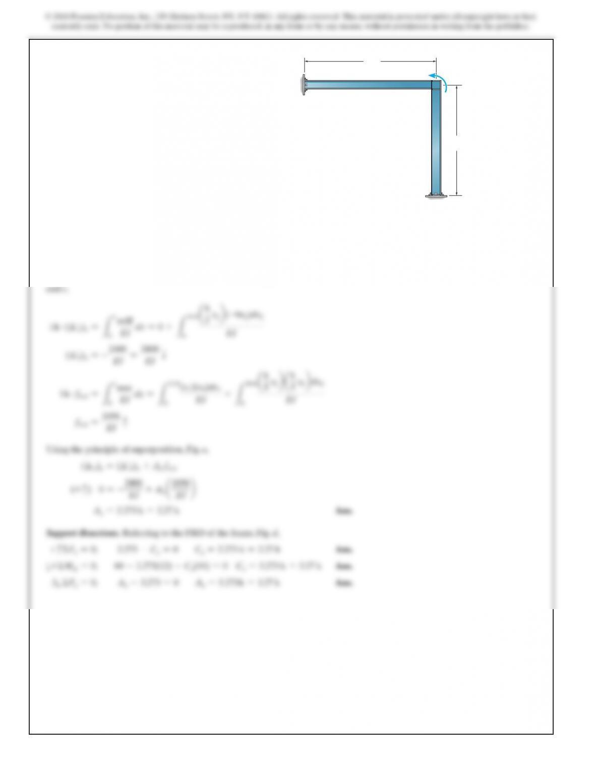
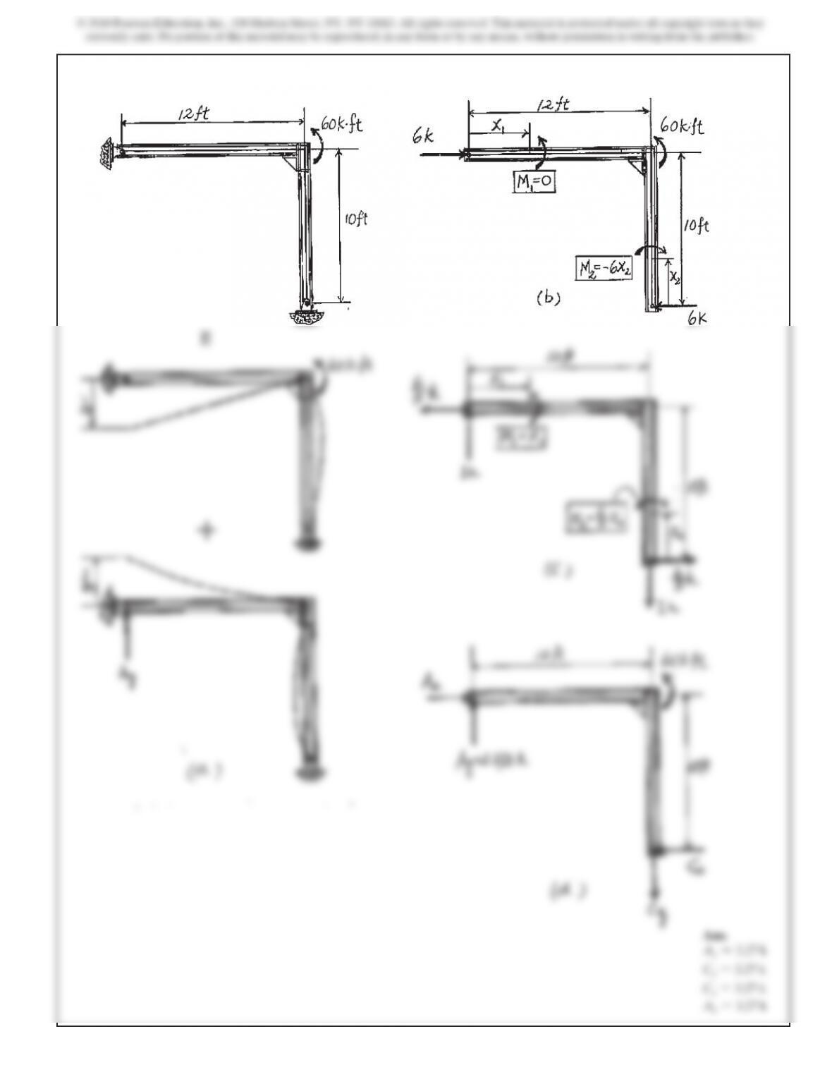
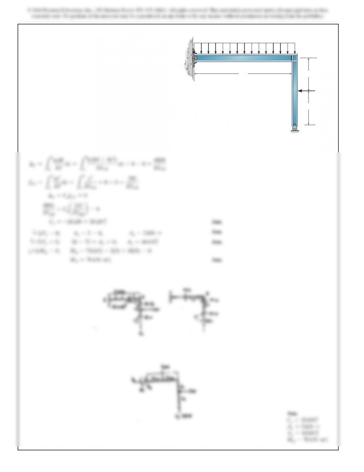
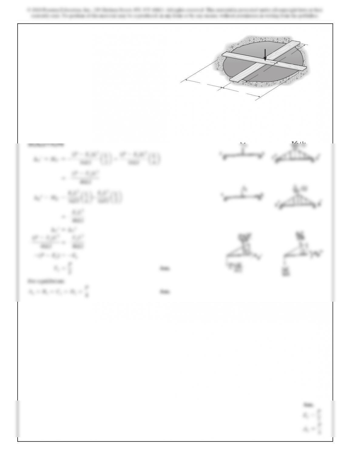
9–18. Determine the reactions at the supports. Assume A and
C are pin supported and B is fixed connected. EI is constant.
10 ft
12 ft
C
B
A
60 k?ft
SOLUTION
Compatibility Equation. Referring to Fig. a, the required dis-
placements can be determined using the virtual work method.
Using the virtual and real moment functions shown in Figs. b
446
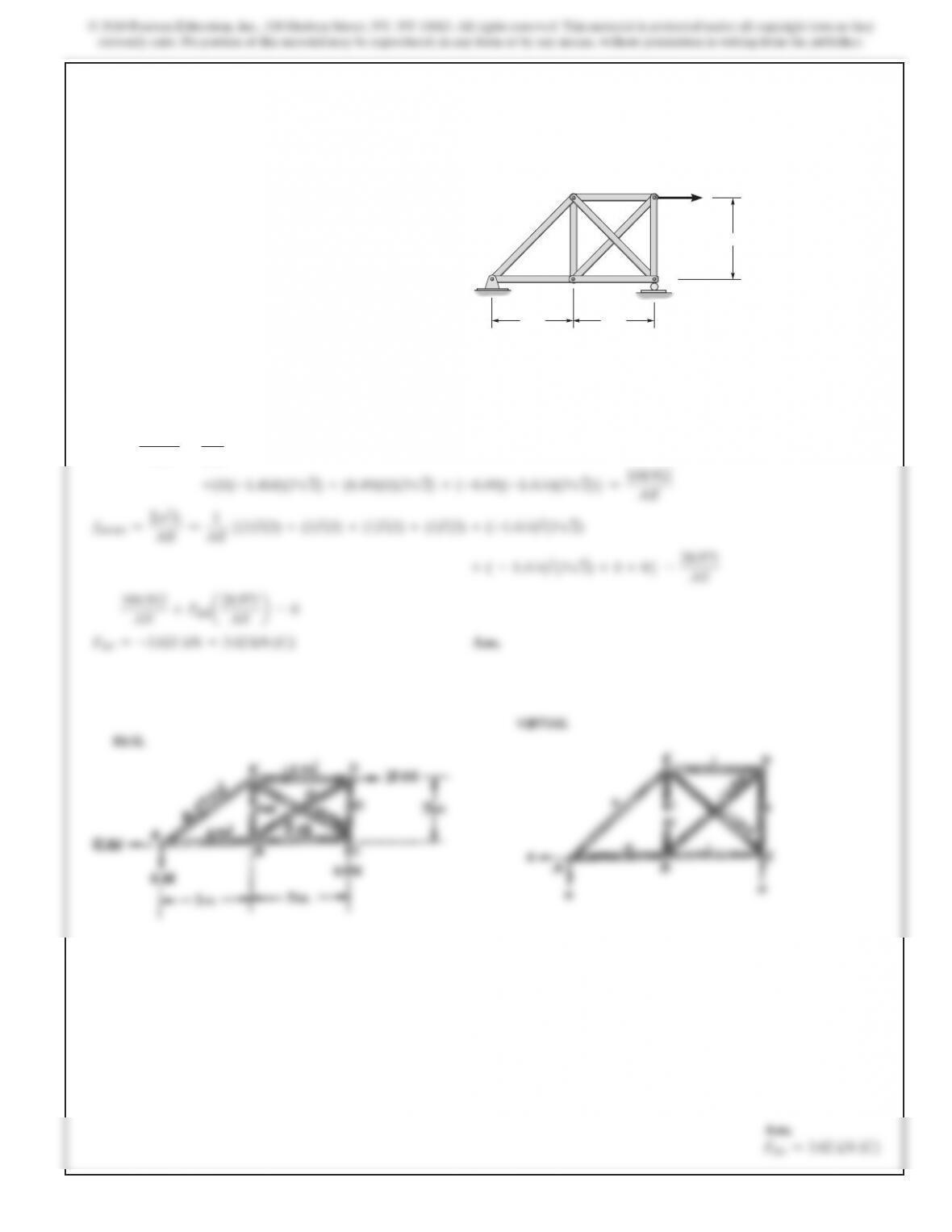
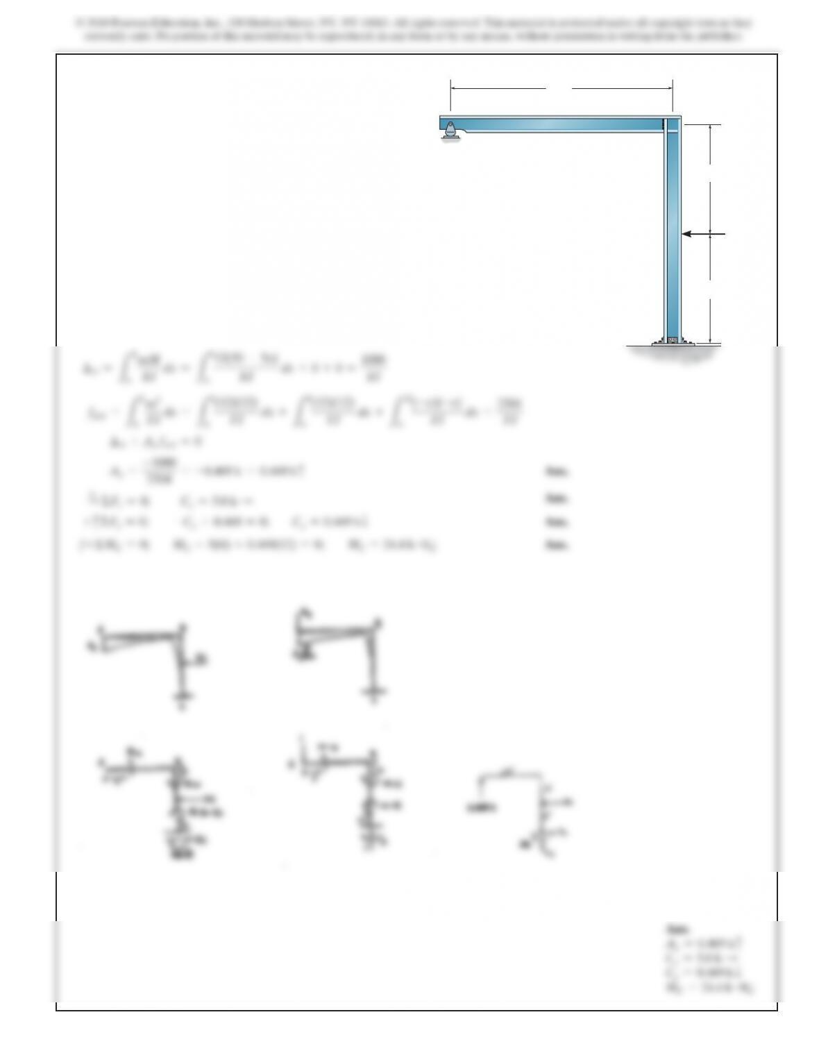
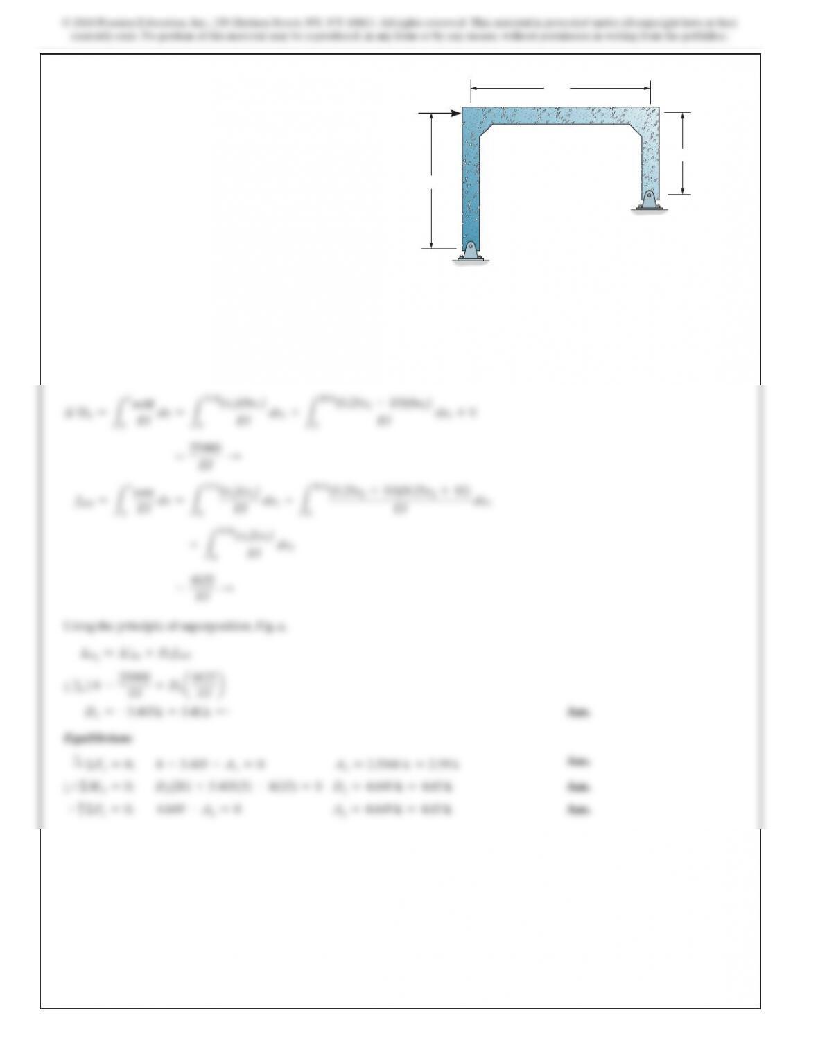
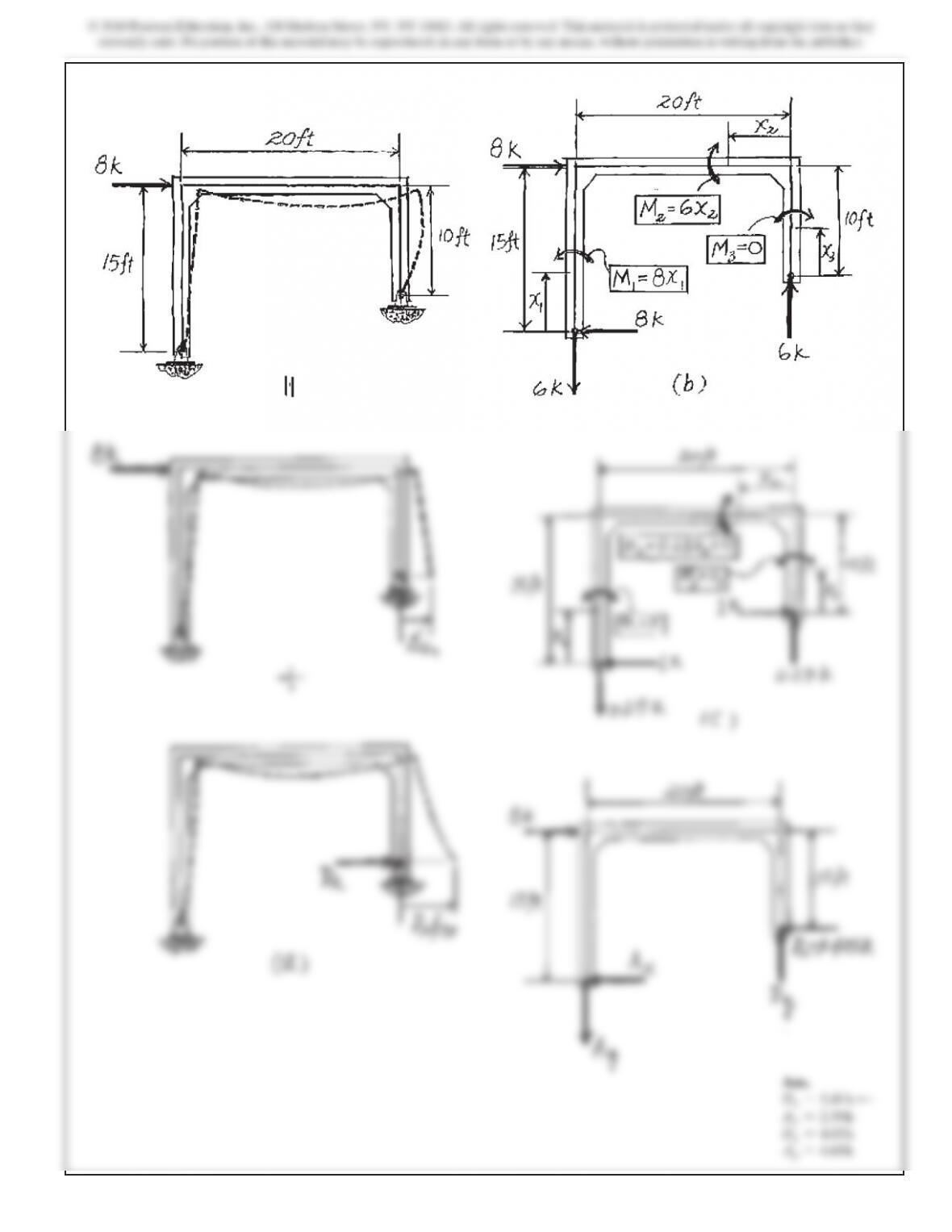
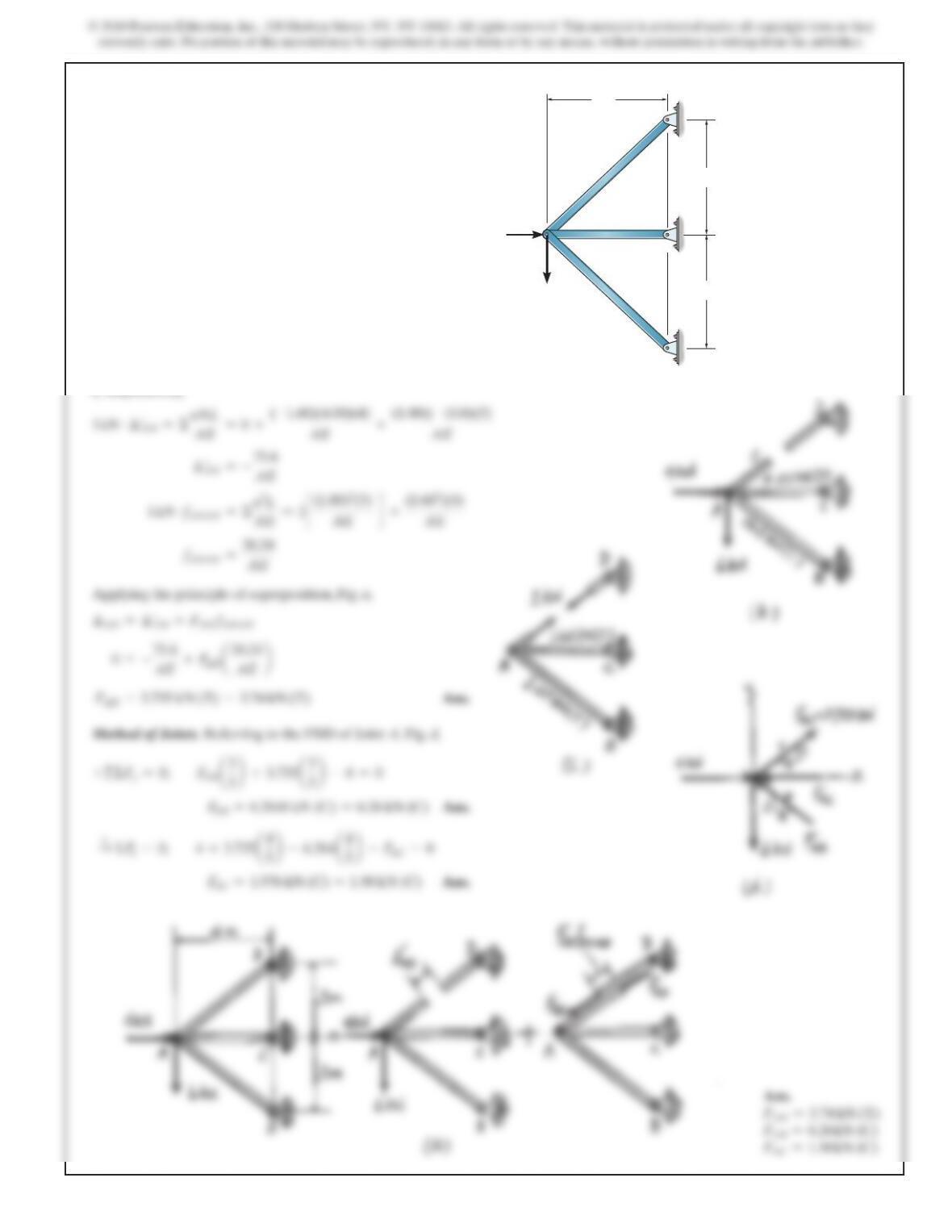
9–21. Determine the reactions at the supports. Assume A and
D are pins. EI is constant.
BC
A
D
8 k
20 ft
15 ft
10 ft
SOLUTION
Compatibility Equation. Referring to Fig. a, and the real and
virtual moment functions shown in Figs. b and c, respectively,
mM
(x
1
)(8x
1
)
(0.25x
2
+10)(6x
2
)
448
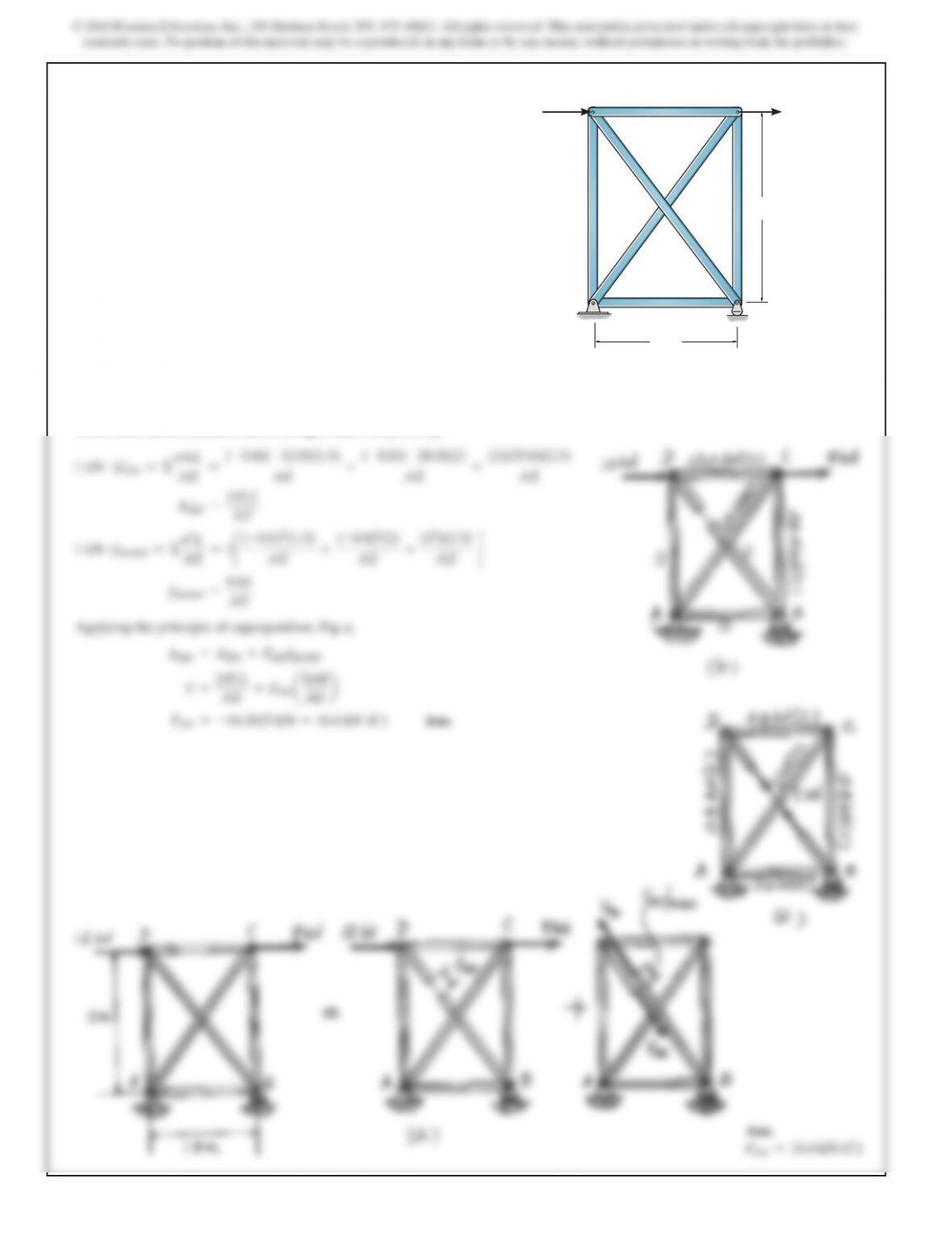
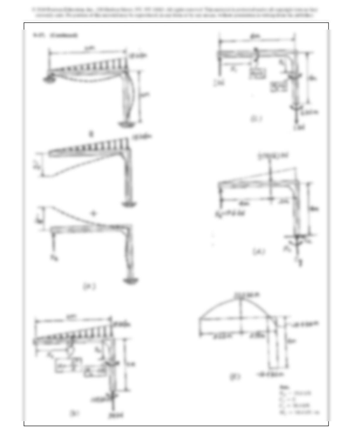
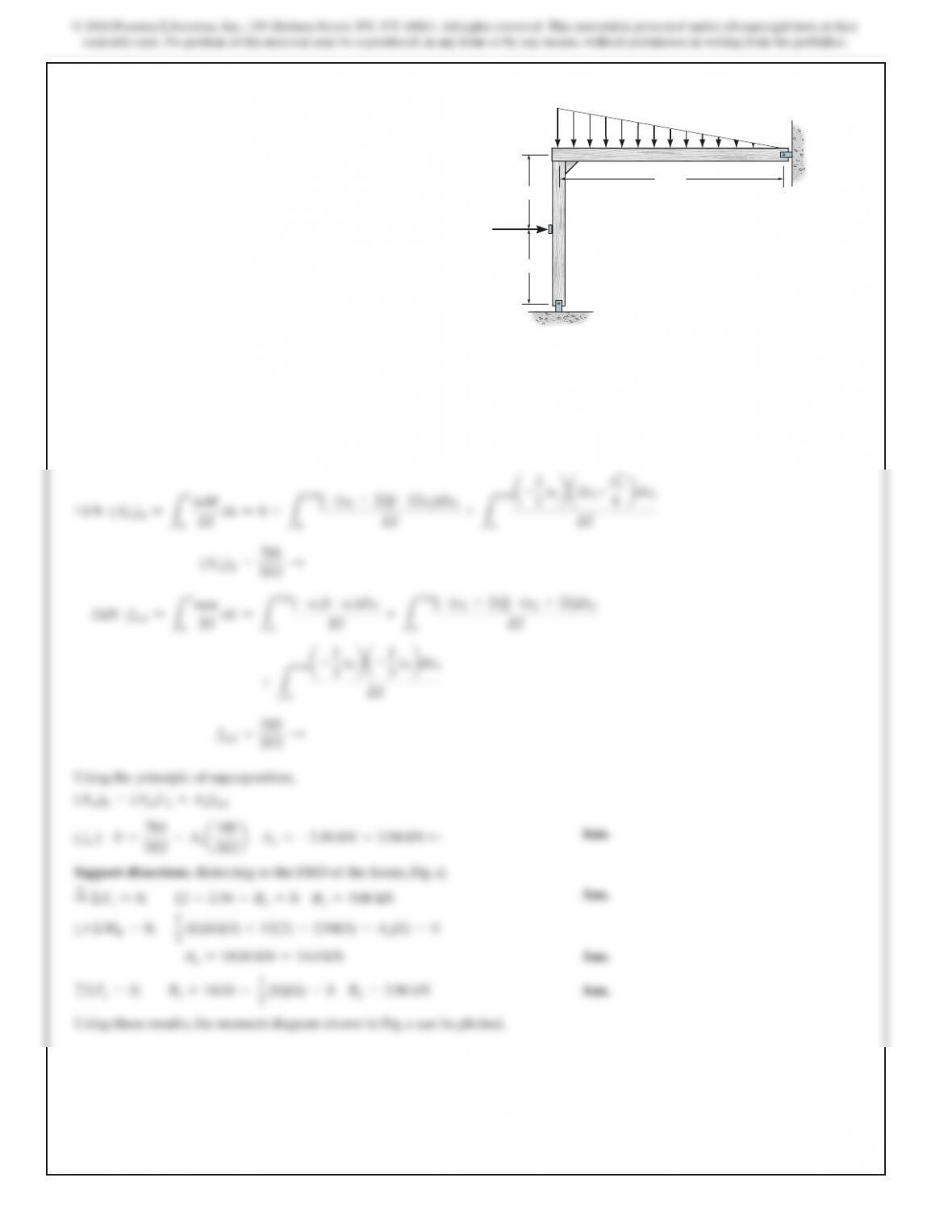
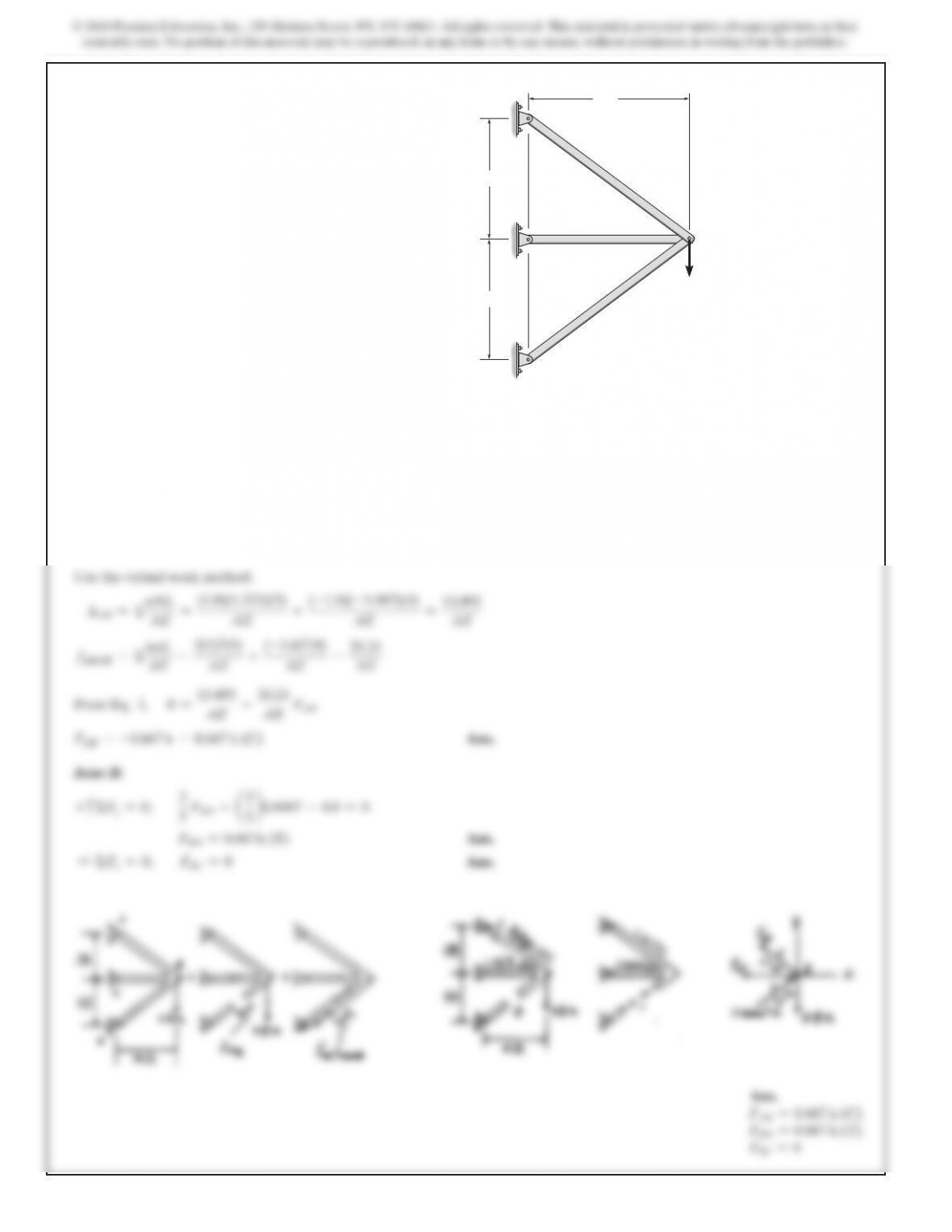
9–22. Determine the reactions at the supports, then draw the
moment diagrams for each member. Assume A and B are pins
and the joint at C is fixed connected. EI is constant.
2 m
B
2 m
C
A
6 m
12 kN
6 kN>m
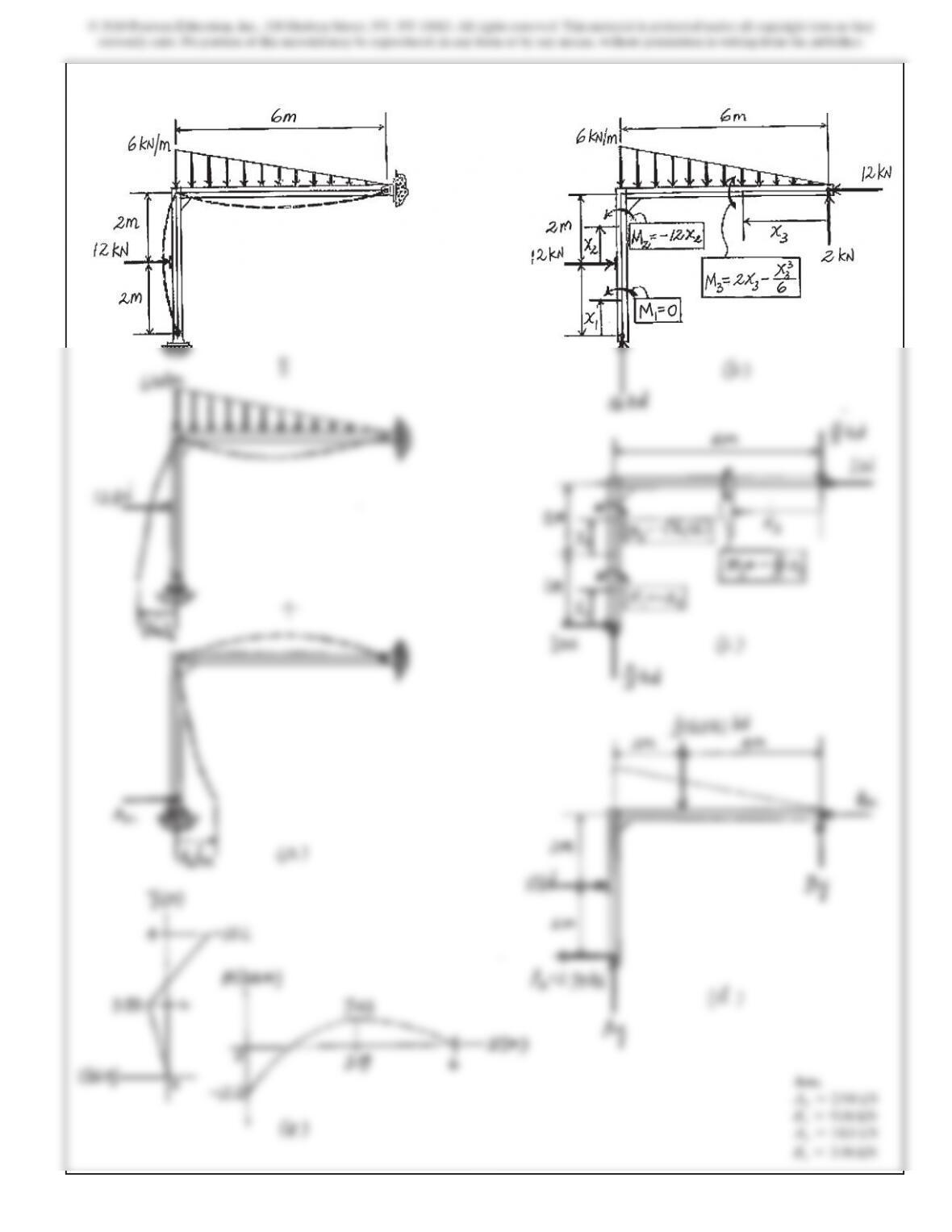
SOLUTION
Compatibility Equation. Referring to Fig. a, the required dis-
placements can be determined using the virtual work method.
Using virtual and real moment functions shown in Figs. b and c,
L
mM
2
m
[–(x2+2)](–12x2)dx2
6
m
a
–
2
3 x3
ba
2x3–
x
3
3
6
b
dx3
450
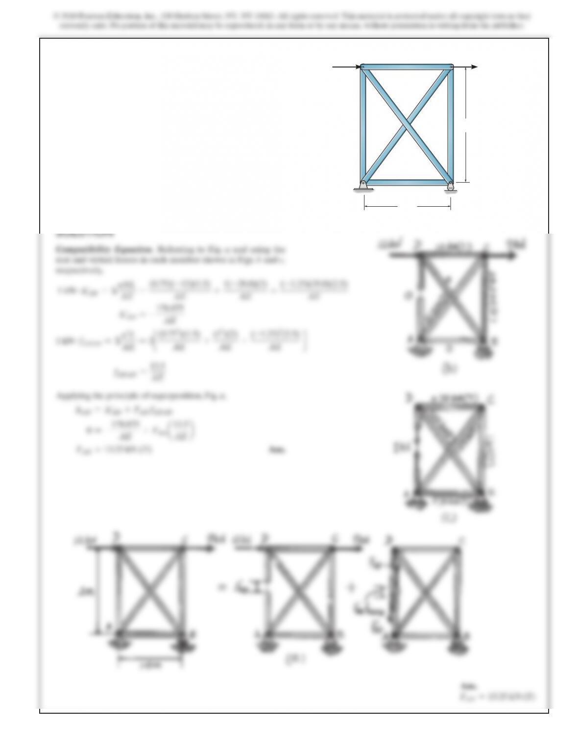
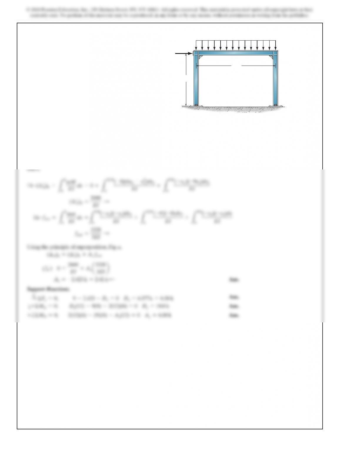
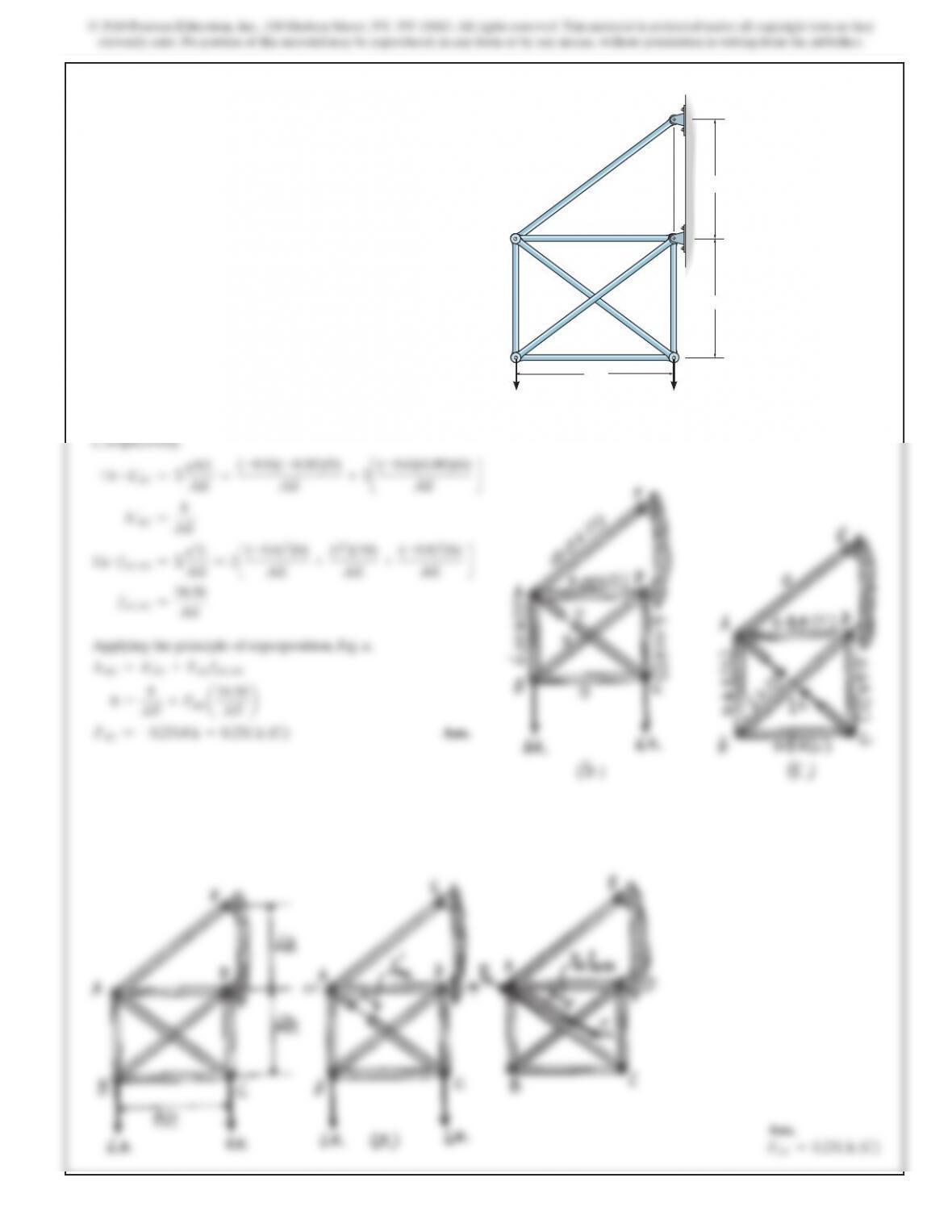
9–23. Determine the reactions at the supports. Assume A and
D are pins. EI is constant.
BC
D
A
12 ft
8 ft
2 k>ft
9 k
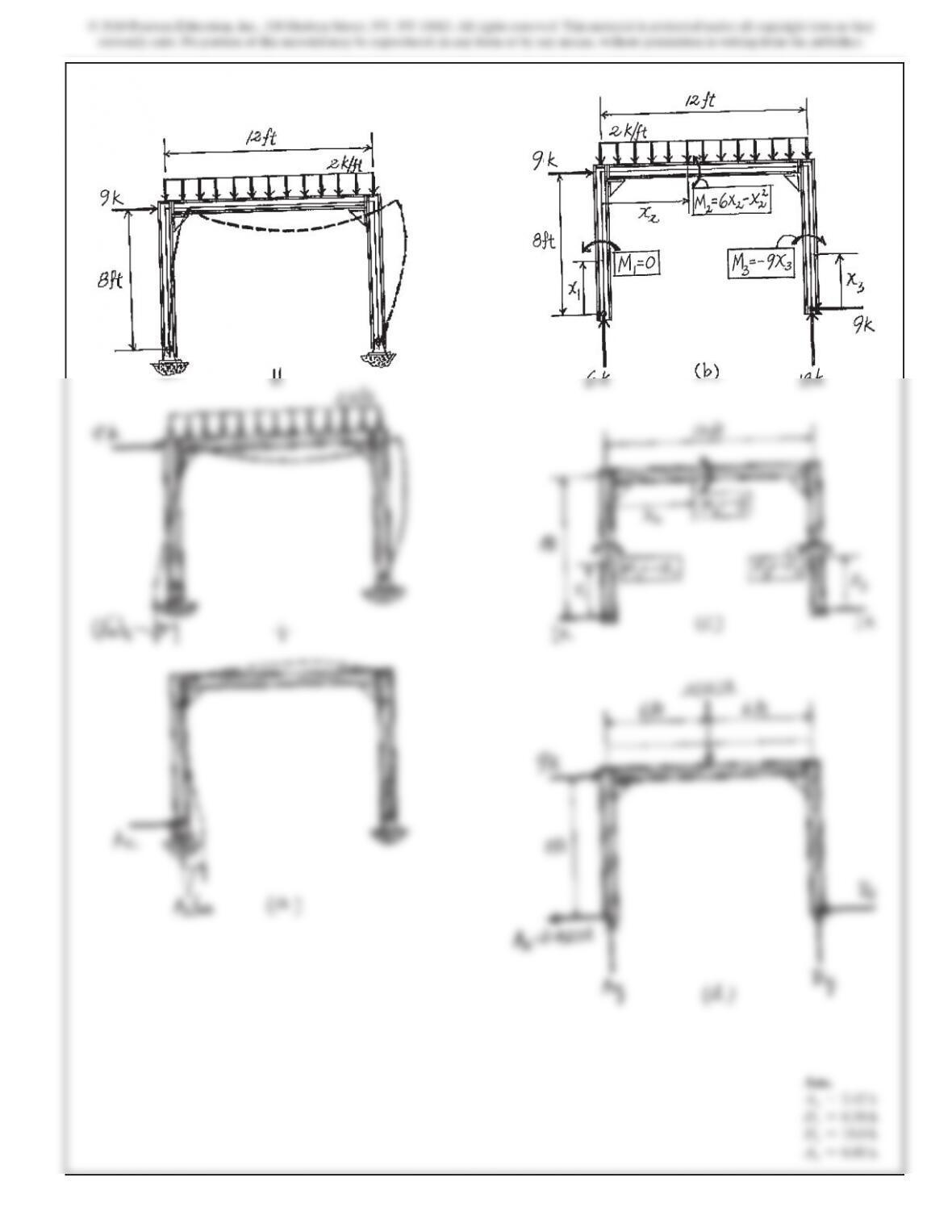
SOLUTION
Compatibility Equation. Referring to Fig. a, the required dis-
placements can be determined using the virtual work method.
Using the virtual and real moment functions shown in Figs. b
455