421
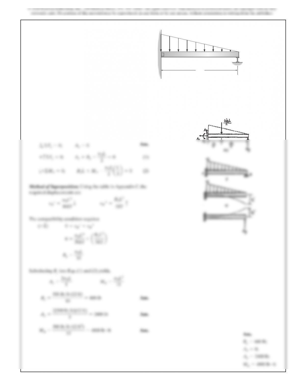
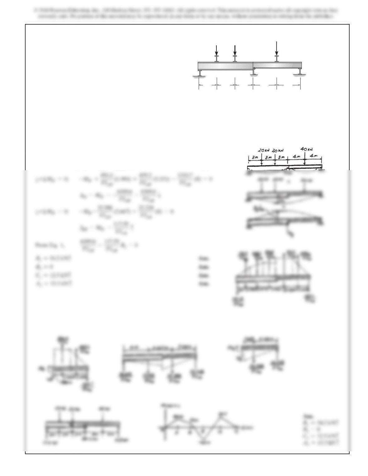
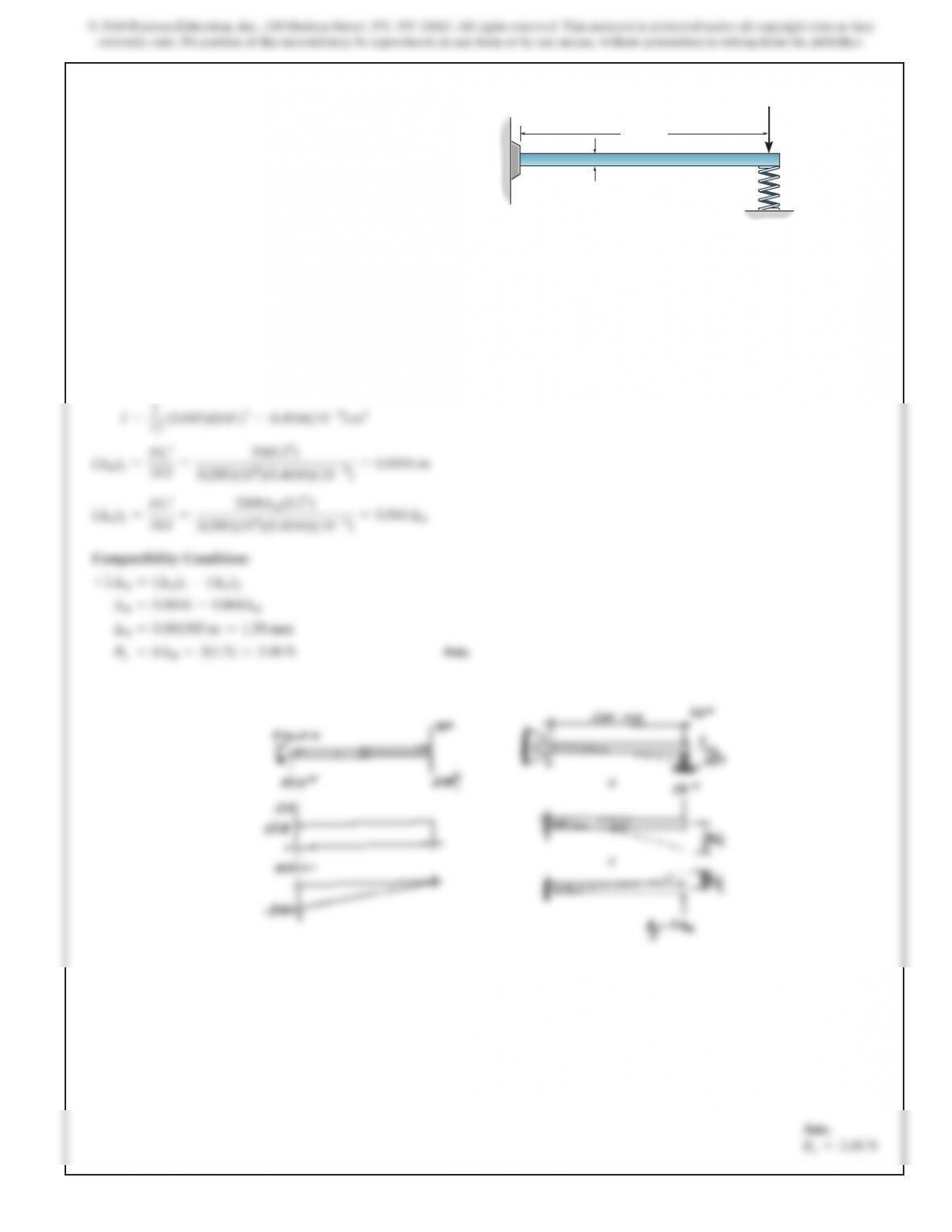
9–1. Determine the reactions at the supports, then draw the
shear and moment diagrams. Assume the support at A is fixed
and B is a roller. EI is constant.
B
A
12 ft
500 lb
/
ft
SOLUTION
Support Reactions: FBD (a).
+
SΣFx=0;
Ax=0
Ans.
+
c
ΣFy=0;
Ay+By–
w
0
L
2
=
0
(1)
a
+ΣMA=0;
ByL+MA–
w
0
L
2aL
3b
=
0
(2)
Method of Superposition: Using the table in Appendix C, the
required displacements are
v
B′=
w
0
L4
30EI
T
v
B′′ =
B
y
L3
3EI
c
The compatibility condition requires
(+ T)
0=vB′+vB′′
0
=
w0L
4
30EI
+
aB
y
L3
3EI b
B
y=
w
0
L
10
Substituting By into Eqs. (1) and (2) yields,
A
y=
2w
0
L
5
M
A=
w
0
L2
15
B
y=
500 lb>ft (12 ft)
10
=600 l
b
Ans.
A
y=
2(500 lb>ft)(12 ft)
5
=2400 l
b
Ans.
M
A=
500 lb>ft (12 ft2)
15
=4800 lb #f
t
Ans. Ans.
By=600 lb;
Ax=0;
Ay=2400 lb;
MA=4800 lb #ft
422
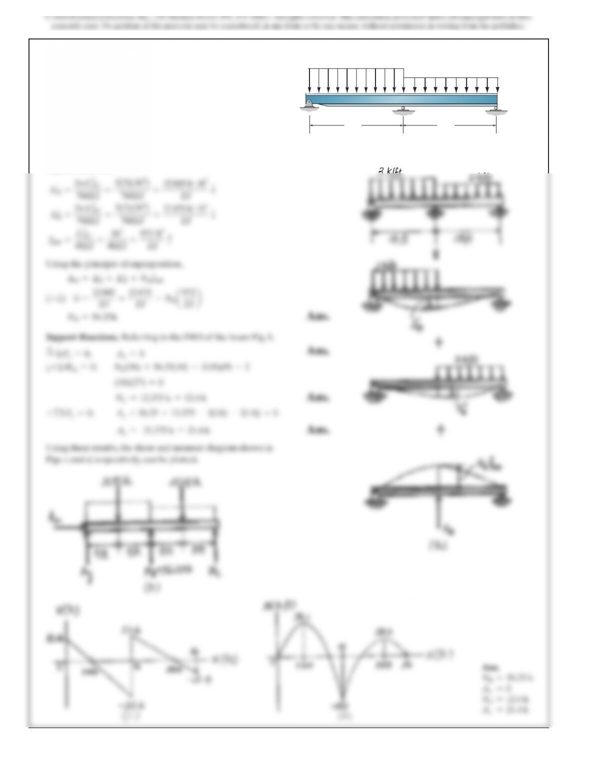
9–2. Determine the reactions at the supports A, B, and C,
then draw the shear and moment diagrams. EI is constant.
A
BC
18 ft 18 ft
3 k>ft
2 k>ft
SOLUTION
Compatibility Equation. Referring to Fig. a, the required
displacements are
∆
′
B=
5wL
AC
4
768EI
=
5(3)(364)
768EI
=
32805 k
#
ft
3
EI
T
∆
″
B=
5wL
AC
4
768EI
=
5(2)(364)
768EI
=
21870 k
#
ft
3
EI
T
fBB =
L
AC
3
48EI
=
36
3
48EI
=
972 ft
3
EI
c
Using the principle of superposition,
∆B=∆′
B+∆″
B+NBfBB
(+ T)
0=
32805
EI
+
21870
EI
–NB
a972
EI b
NB=56.25
k
Ans.
Support Reactions. Referring to the FBD of the beam Fig. b,
+
SΣFx=0;
Ax=0
Ans.
a+ΣMA=0;
NC(36) +56.25(18) –3(18)(9) –2
(18)(27) =0
NC=12.375 k =12.4 k
Ans.
+
c
ΣFy=0;
Ay+56.25 +12.375 –3(18) –2(18) =0
Ay= 21.375 k =21.4 k
Ans.
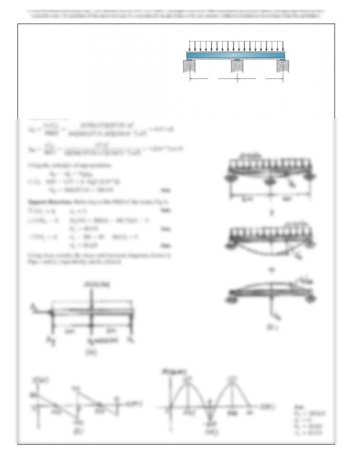
Using these results, the shear and moment diagram shown in
Figs. c and d, respectively, can be plotted.
Ans.
NB=56.25 k
Ax=0
NC=12.4 k
Ay=21.4 k
423
SOLUTION
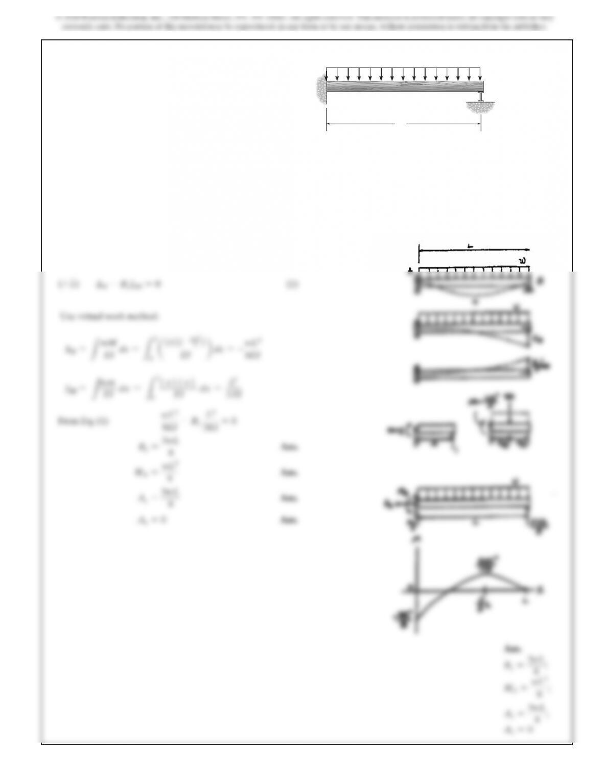
Compatibility Equation:
(+ T)
∆B–ByfBB =0
(1)
Use virtual work method:
∆B=
L
mM
EI
dx =
LL
0a1
x
21
–
wx2
2
2
EI b
dx =–wL
4
8EI
f
BB =
L
mm
EI
dx =
LL
0
1
x
21
x
2
EI
dx =
L
3
3EI
From Eq. (1)
wL4
8EI
–By
L3
3EI
=
0
B
y=
3wL
8
Ans.
M
A=
wL2
8
Ans.
A
y=
5wL
8
Ans.
Ax=0
Ans.
Ans.
B
y=
3wL
8
;
M
A=
wL2
8
;
Ay=
5wL
8
;
Ax=0
9–3. Determine the reactions at the supports, then draw the
moment diagram. Assume the support at B is a roller. EI is
constant.
A
L
B
w
425
SOLUTION
Compatibility Equation:
(+ T)
∆B–ByfBB =0
(1)
a
+ΣMB′=0;
–MB′+
891.0
EIAB
(1.990) +
439.2
EIAB
(5.333) –
1310.7
EIAB
(8) =
0
∆B=MB′=–
6369.6
EIAB
=
6369.6
EIAB
T
a
+ΣMB′=0;
–MB′–
22.588
EIAB
(2.667) +
22.228
EIAB
(8) =
0
fBB =MB′=
117.59
EIAB
c
From Eq. 1,
6369.6
EIAB
–
117.59
EIAB
By=
0
By=54.2 kN
c
Ans.
Bx=0
Ans.
Cy=12.5 kN
c
Ans.
Ay=13.3 kN
c
Ans.
Ans.
B
y
=54.2 kN
c
Bx=0
C
y
=12.5 kN
c
A
y
=13.3 kN
c
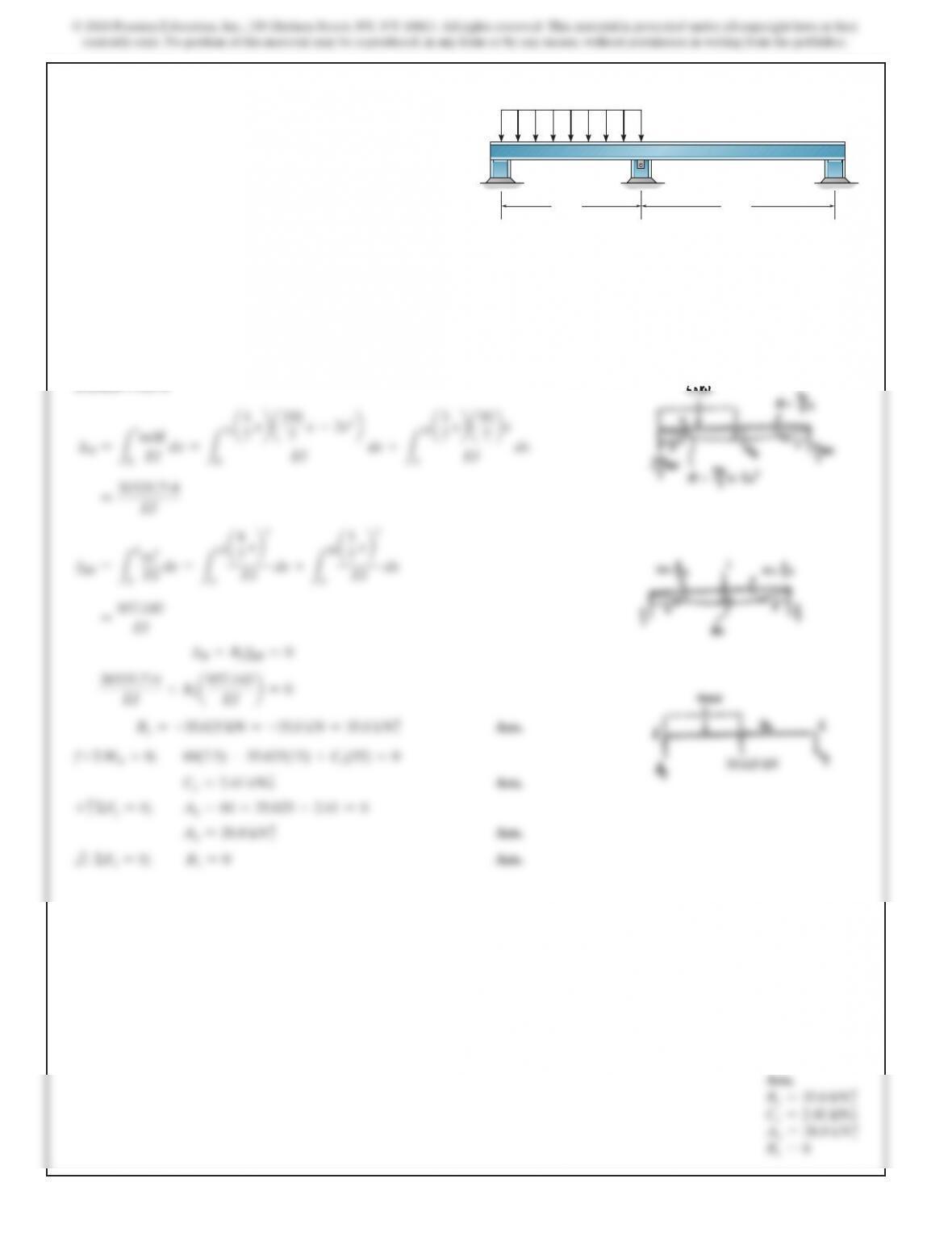
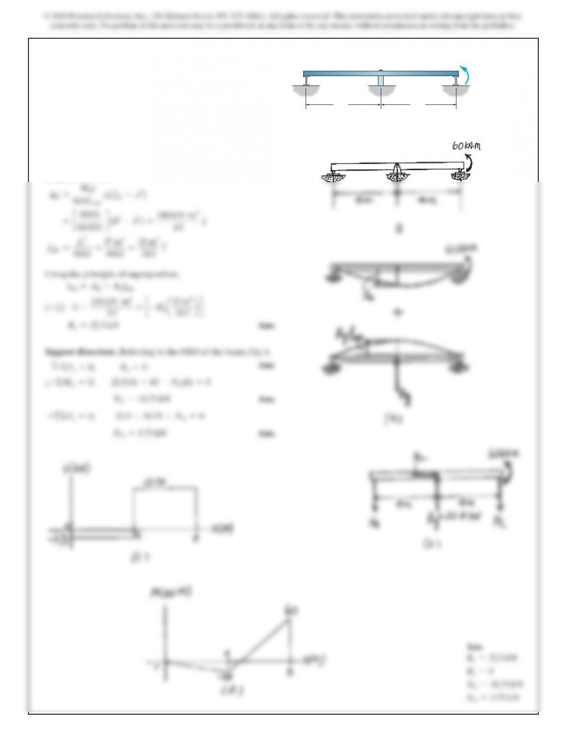
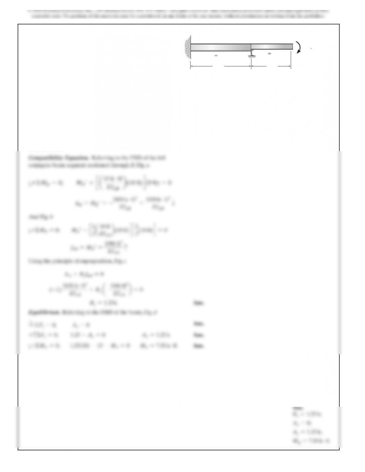
9–5. Determine the reactions at the supports, then draw the
moment diagram. The moment of inertia for each segment is
shown in the figure. Assume A and C are rollers and B is a pin.
Take
E=200 GPa
.
20 kN
40 kN
ABC
3 m 3 m 3 m 4 m 4 m
IAB 5 120(106) mm4IBC 5 90(106) mm4
20 kN
SOLUTION
mM
(x–18)(41x–474 –x2)
45684
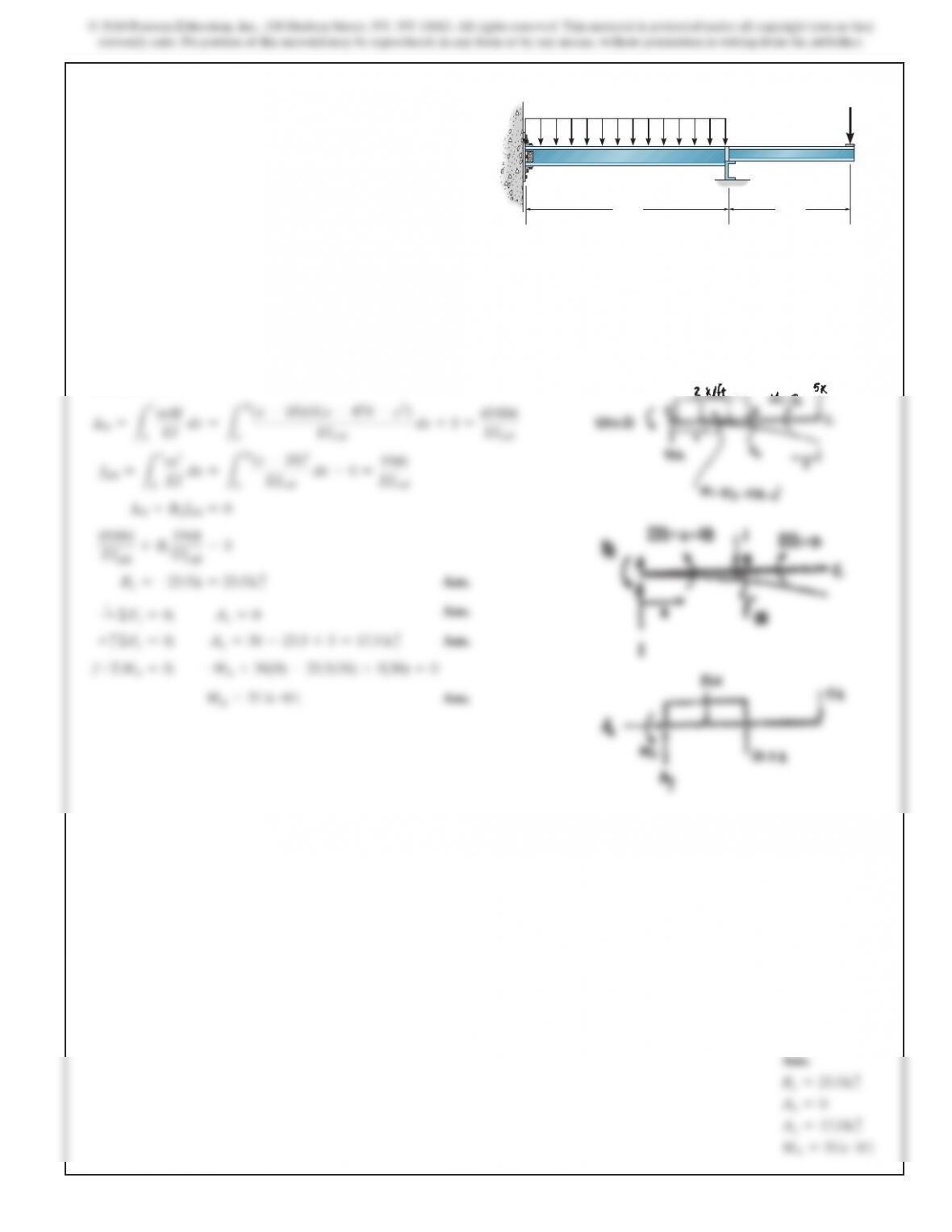
9–11. Determine the reactions at the supports. Assume the
support at A is fixed and B is a roller. Take
E=29(103) ksi
.
The moment of inertia for each segment is shown in the figure.
A
BC
18 ft 12 ft
2 k>ft
5 k
IAB 5 600 in4IBC 5 300 in4
© 2018 Pearson Education, Inc., 330 Hudson Street, NY, NY 10013. All rights reserved. This material is protected under all copyright laws as they
currently exist. No portion of this material may be reproduced, in any form or by any means, without permission in writing from the publisher.
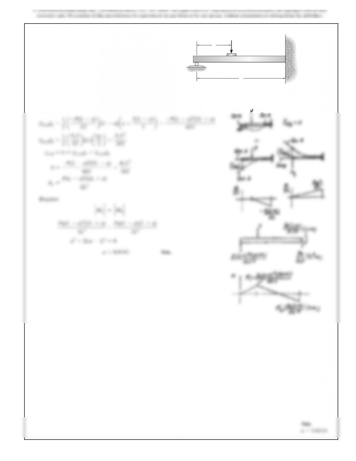
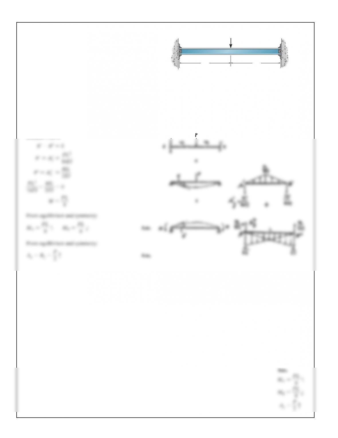
*9–12. Determine the reactions at the fixed supports, A and
B. EI is constant. A
P
B
L
—
2
L
—
2
SOLUTION
u′–u″=0
u′=A′
y=
PL2
16EI
u
″=A″
y=
ML
2EI
PL2
16EI
–
ML
2EI
=
0
M
=
PL
8
From equilibrium and symmetry:
MA=
PL
8
B
MB=
PL
8
A
Ans.
From equilibrium and symmetry:
Ay=By=
P
2
c
Ans.
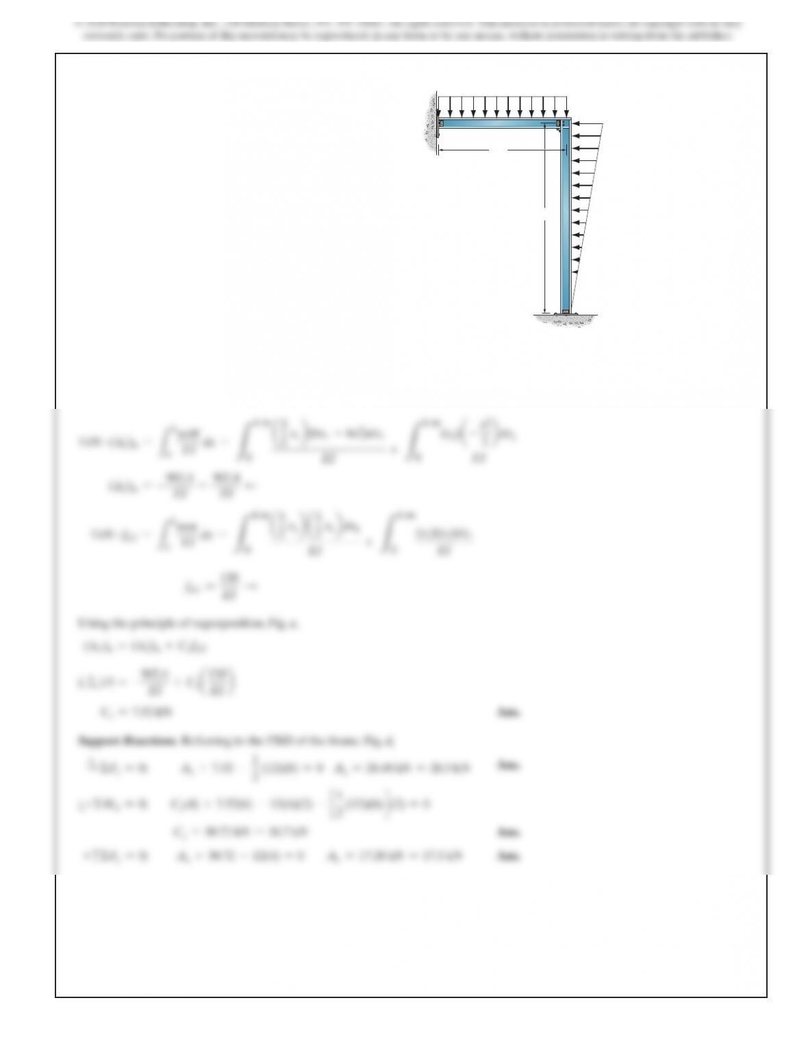
433
B
A
C
6 m
4 m
12 kN>m
12 kN>
m
9–13. Determine the reactions at the supports. Assume A
and C are pins and the joint at B is fixed connected. EI is
constant.
SOLUTION
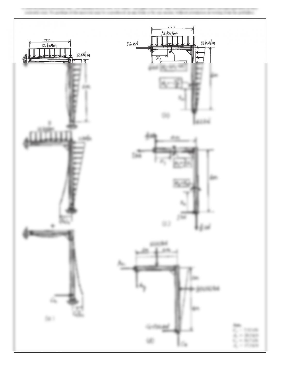
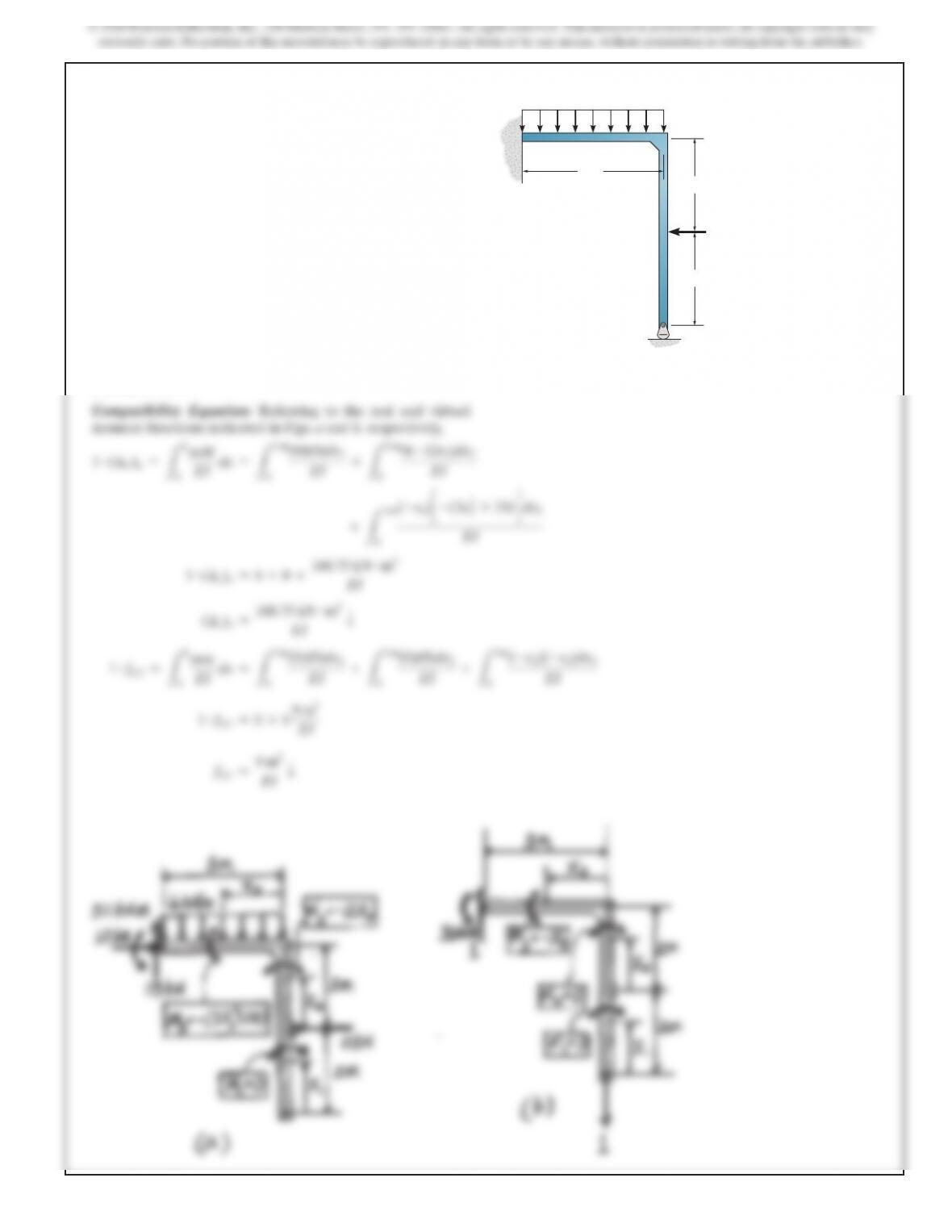
Compatibility Equation. Referring to Fig. a, the required dis-
placements can be determined using the virtual work method.
Using the virtual and real moment functions shown in Figs. b
and c,
1
kN #(∆′
C)n=
LL
0
mM
EI
dx =
L4 m
0
a3
2 x1
b
(6x1–6x1
2)dx1
EI
+
L6 m
0
(x2)
a
–
x
2
3
2
b
dx2
EI
(
∆′
C)n=–
902.4
EI
=
902.4
EI
d
1
kN #fCC =
LL
0
mm
EI
dx =
L4 m
0
a3
2 x1
ba3
2 x1
b
dx1
EI
+
L6 m
0
(x
2
)(x
2
)dx
2
EI
fCC =
120
EI
S
Using the principle of superposition, Fig. a,
(∆C)n=(∆′
C)n+CxfCC
(
+
S) 0 =–
902.4
EI
+Cx
a120
EI b
Cx=7.52 kN
Ans.
Support Reactions. Referring to the FBD of the frame, Fig. d,
+
S
ΣFx=0;
Ax+7.52 –
1
2
(12)(6) =0
Ax=28.48 kN =28.5 kN Ans.
a
+ΣMA=0;
Cy(4) +7.52(6) –12(4)(2) –
c1
2
(12)(6)
d
(2) =
0
Cy=30.72 kN =30.7 kN
Ans.
+
c
ΣFy=0;
Ay+30.72 –12(4) =0
Ay=17.28 kN =17.3 kN
Ans.
9–13. (Continued)
435
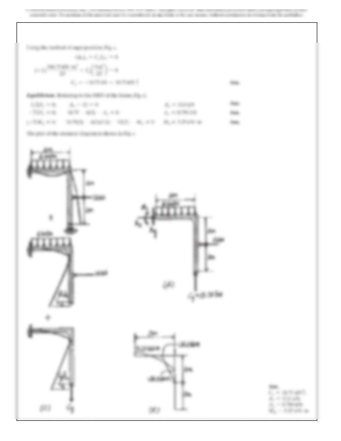
9–14. Determine the reactions at the supports, then draw the
moment diagrams for each member. EI is constant.
A
B
C
3 m
6 kN>m
12 kN
2 m
2 m
SOLUTION
EI
436
Ans.
Cy=18.75
kN
c
;
Ax=12.0
kN;
Ay=0.750
kN;
MA=5.25
kN #m
437
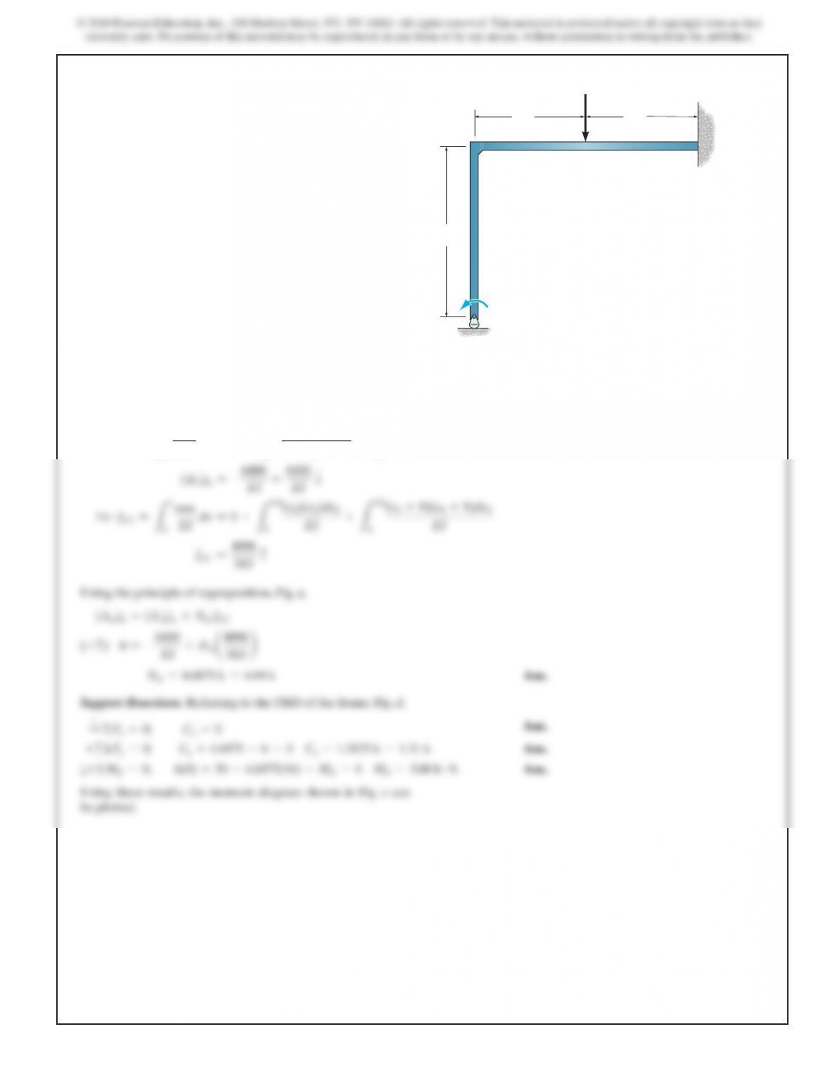
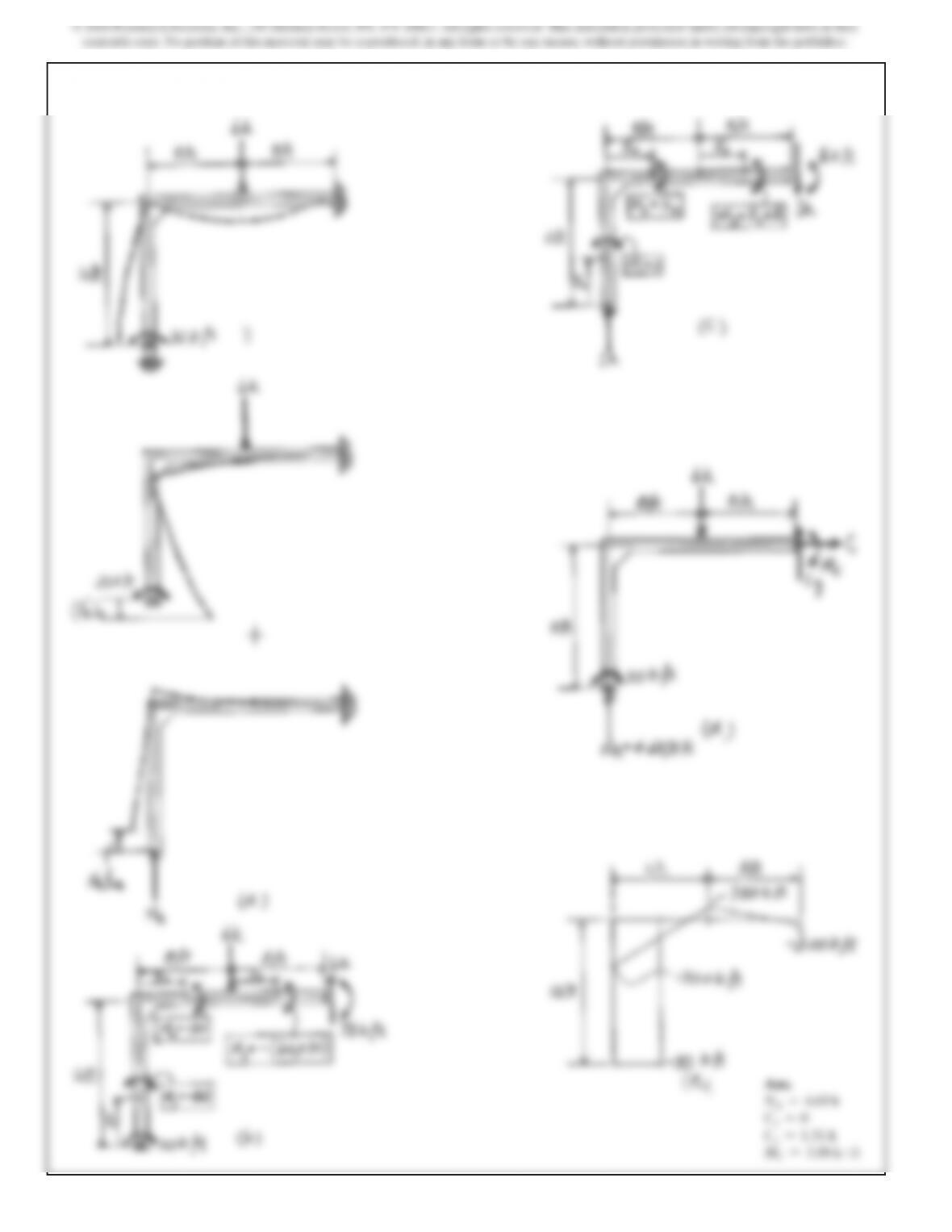
9–15. Determine the reactions at the supports, then draw the
moment diagram for each member. EI is constant.
B
A
C
12 ft
8 ft 8 ft
6 k
30 k?ft
SOLUTION
Compatibility Equation. Referring to Fig. a, the required
displacements can be determined using the virtual work
method. Using the virtual and real moment functions shown
in Figs. b and c,
1
k#(∆′
A)y=
LL
0
mM
EI dx =0+
L8
ft
0
(x
2
)(–30)dx
2
EI +
L8
ft
0
(x3+8)[–(6x3+30)]dx
3
(
∆′
A)y=–
6400
EI
=
6400
EI
T
1
mm
(x
2
)(x
2
)dx
2
(x
3
+8)(x
3
+8)dx
3
9–15. (Continued)
© 2018 Pearson Education, Inc., 330 Hudson Street, NY, NY 10013. All rights reserved. This material is protected under all copyright laws as they
currently exist. No portion of this material may be reproduced, in any form or by any means, without permission in writing from the publisher.
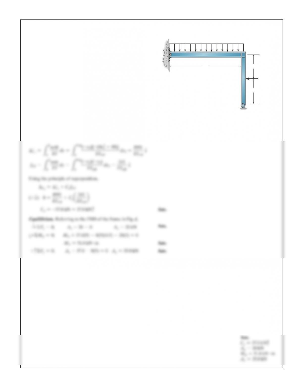
*9–16. Determine the reactions at the supports. Assume A is
fixed connected. E is constant.
B
C
A
20 kN
3 m
3 m
9 m
8 kN>m
IAB 5 1250 (106) mm4
IBC 5 625 (106) mm4
SOLUTION
Compatibility Equation. Referring to Fig. a, and using the real
and virtual moment function shown in Figs. b and c, respectively,
mM
(–x
3
)[–(4x
3
2+60)]
8991
440
© 2018 Pearson Education, Inc., 330 Hudson Street, NY, NY 10013. All rights reserved. This material is protected under all copyright laws as they
currently exist. No portion of this material may be reproduced, in any form or by any means, without permission in writing from the publisher.
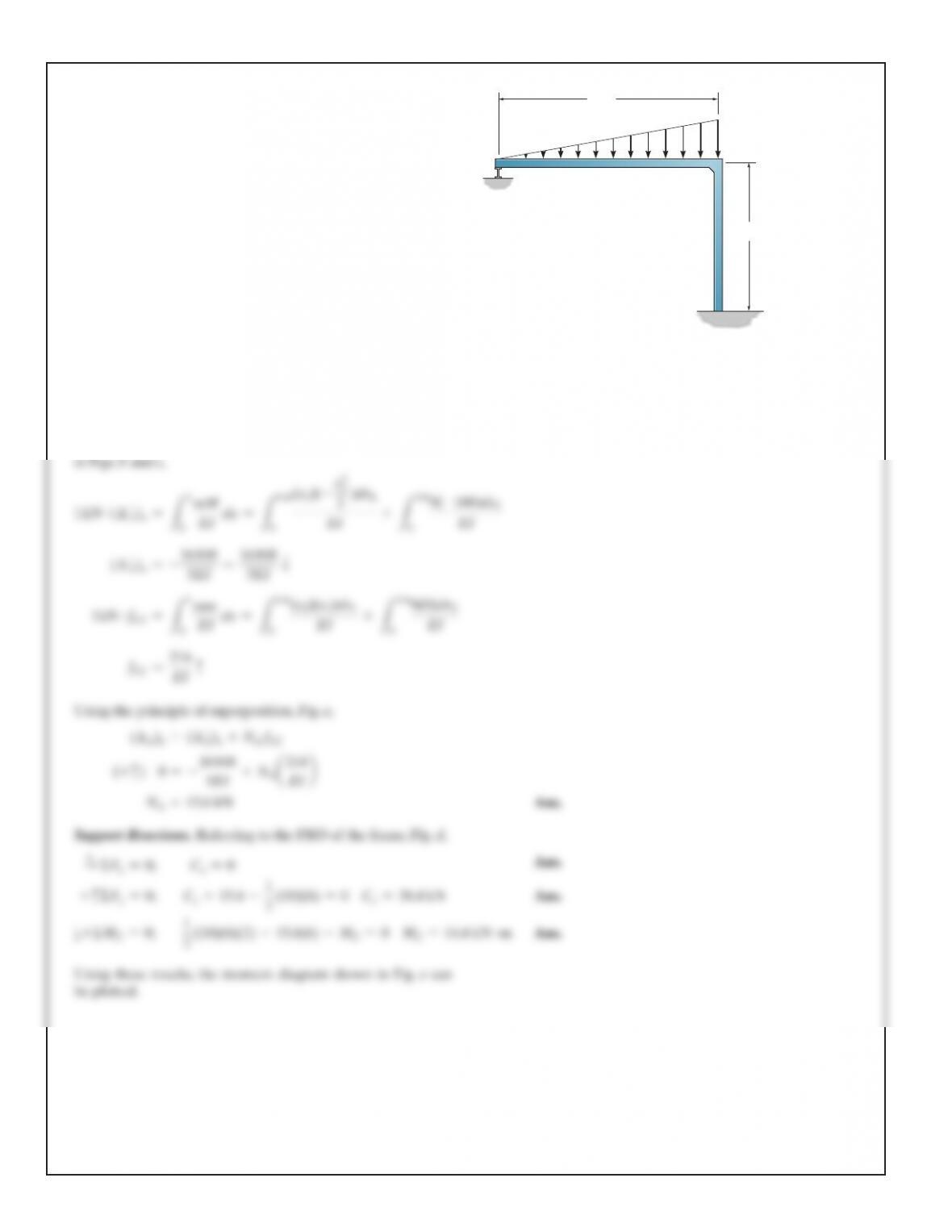
9–17. Determine the reactions at the supports, then draw the
moment diagram for each member. EI is constant.
B
A
C
6 m
4 m
18 kN>
m
SOLUTION
Compatibility Equation. Referring to Fig. a, the required
displacements can be determined using the virtual work
method. Using the virtual and real moment functions shown