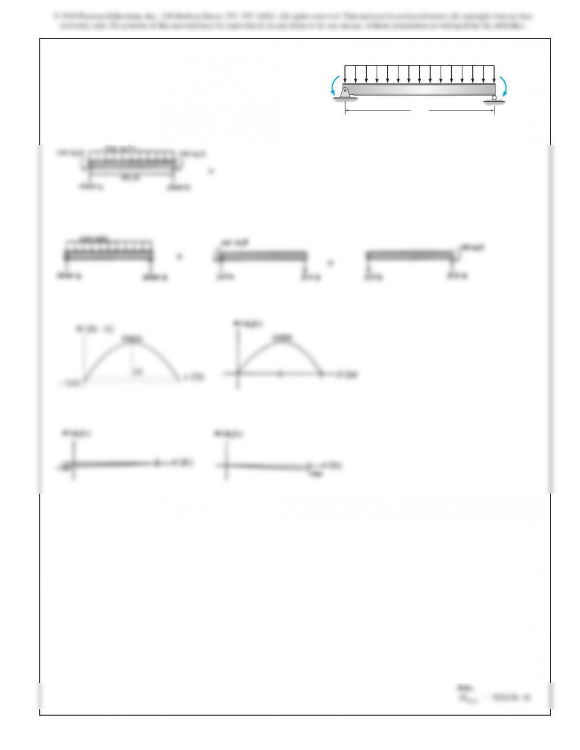
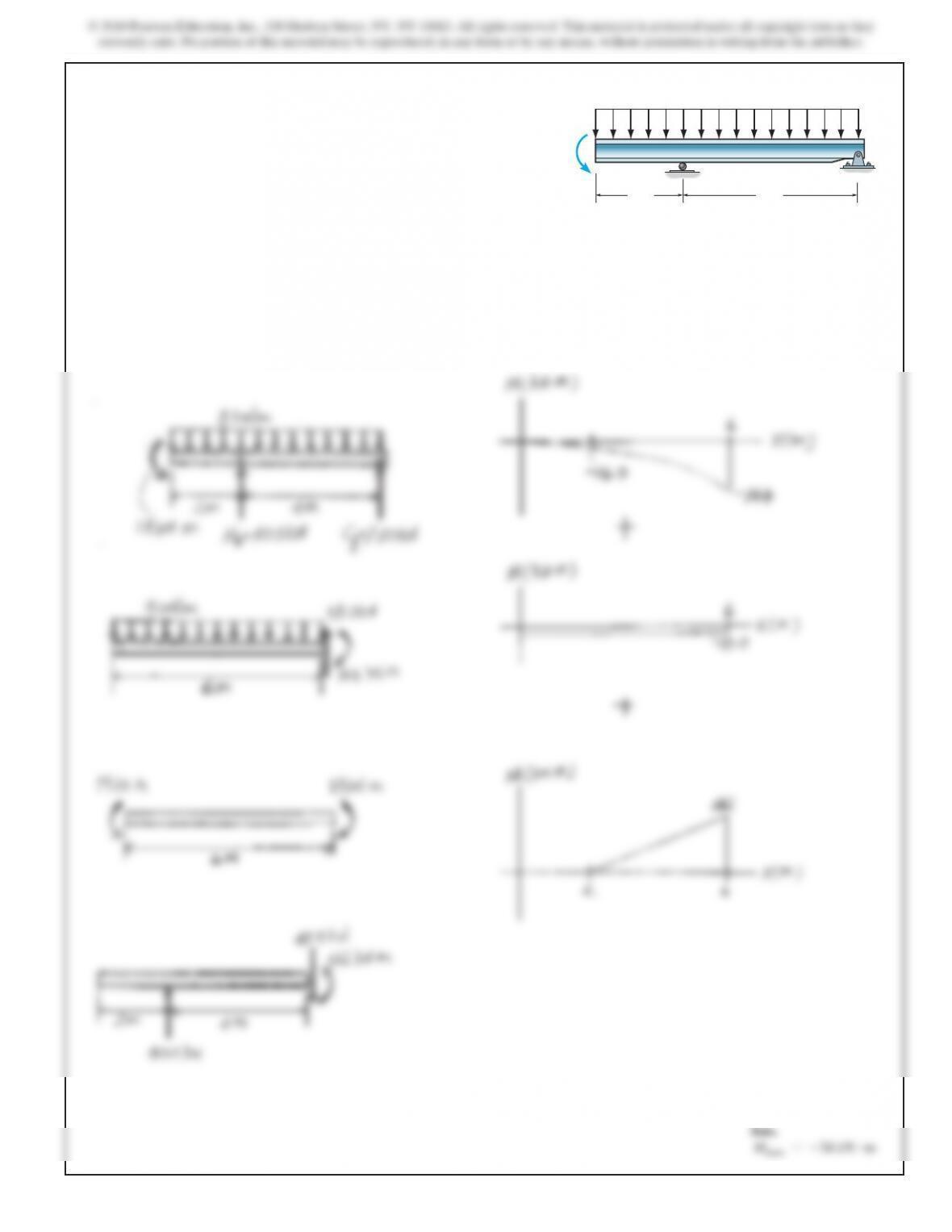
4–51. Draw the moment diagrams for the beam using the
method of superposition. Consider the beam to be simply
supported at A and B as shown.
200 lb
>
ft
100 lb
ft 100 lb
ft
AB
20 ft
??
SOLUTION
178
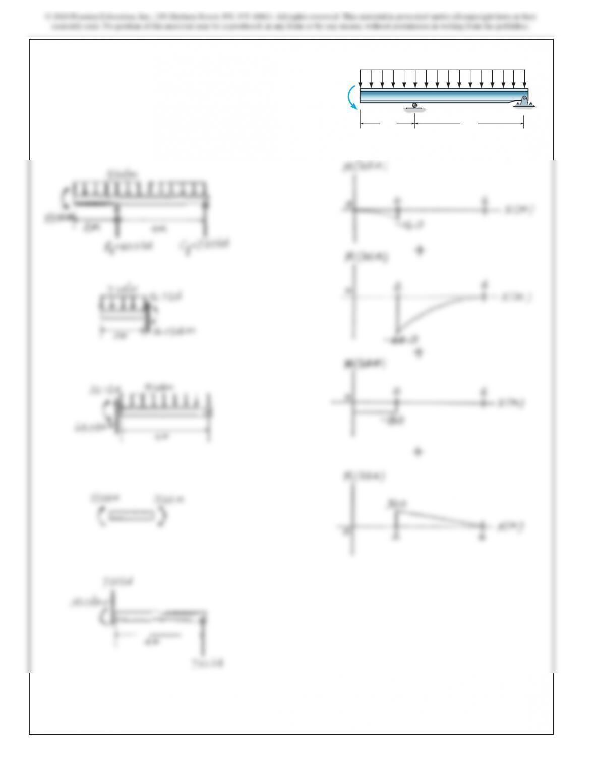
*4–52. Draw the moment diagrams for the beam using the
method of superposition.
80 lb/ft
12 ft12 ft
600 lb
SOLUTION
4–53. Draw the moment diagrams for the beam using the
method of superposition. Consider the beam to be simply
supported. Assume A is a pin and B is a roller.
50 lb/ft
10 ft
AB
800 lb
10 ft
750 lb?ft
SOLUTION
4–54. Solve Prob. 4–53 by considering the beam to be
cantilevered from the support at A.50 lb/ft
10 ft
AB
800 lb
10 ft
750 lb?ft
SOLUTION
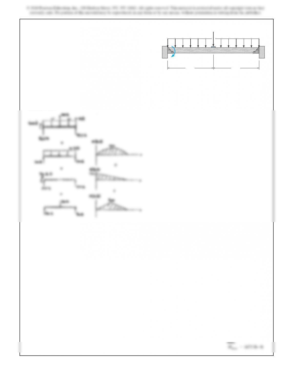
4–55. Draw the moment diagrams for the beam using the
method of superposition. Consider the beam to be cantilevered
from the pin support at C.
A
B
8 kN/m
18 kN
? m
2 m 4 m
C
SOLUTION
182
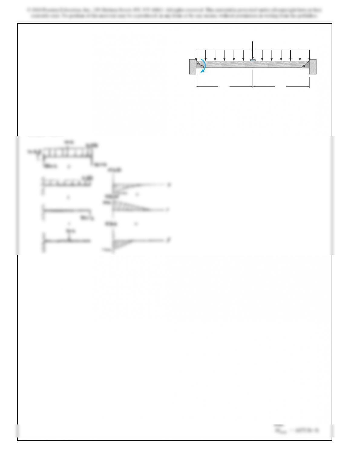
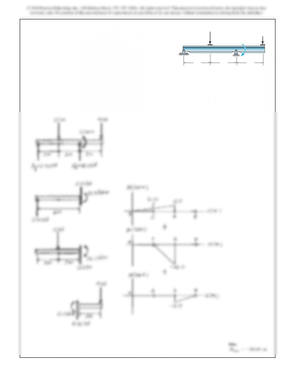
*4–56. Draw the moment diagrams for the beam using the
method of superposition. Consider the beam to be cantilevered
from the roller at B.
A
B
8 kN/m
18 kN
? m
2 m 4 m
C
SOLUTION
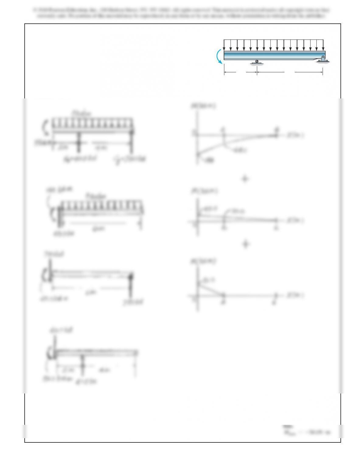
4–57. Draw the moment diagrams for the beam using the
method of superposition. Consider the beam to be cantilevered
from end A.
A
B
8 kN/m
18 kN
? m
2 m 4 m
C
SOLUTION
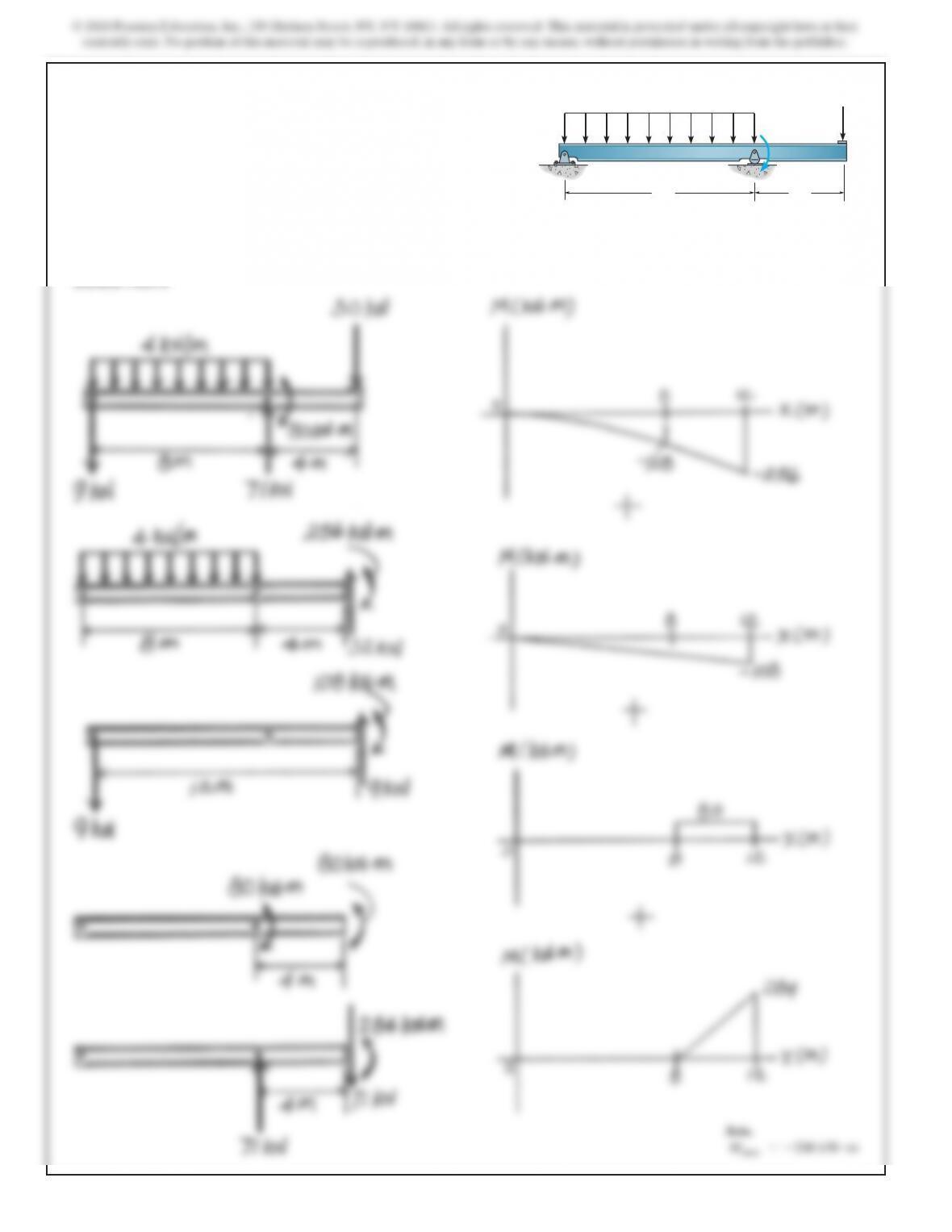
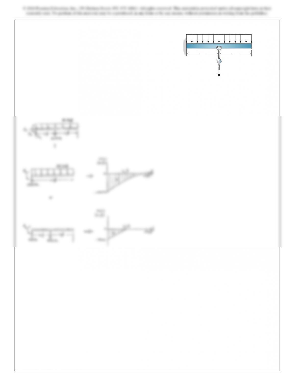
4–58. Draw the moment diagrams for the beam using the
method of superposition. Consider the beam to be cantilevered
from end C.
30 kN
80 kN ?m
4 kN/m
A
B
C
8 m 4 m
SOLUTION
4–59. Draw the moment diagrams for the beam using the
method of superposition. Consider the beam to be cantilevered
from the support at B.
A
B12 kN ? m
3 m 3 m 3 m
C
12 kN
4 kN
SOLUTION
186
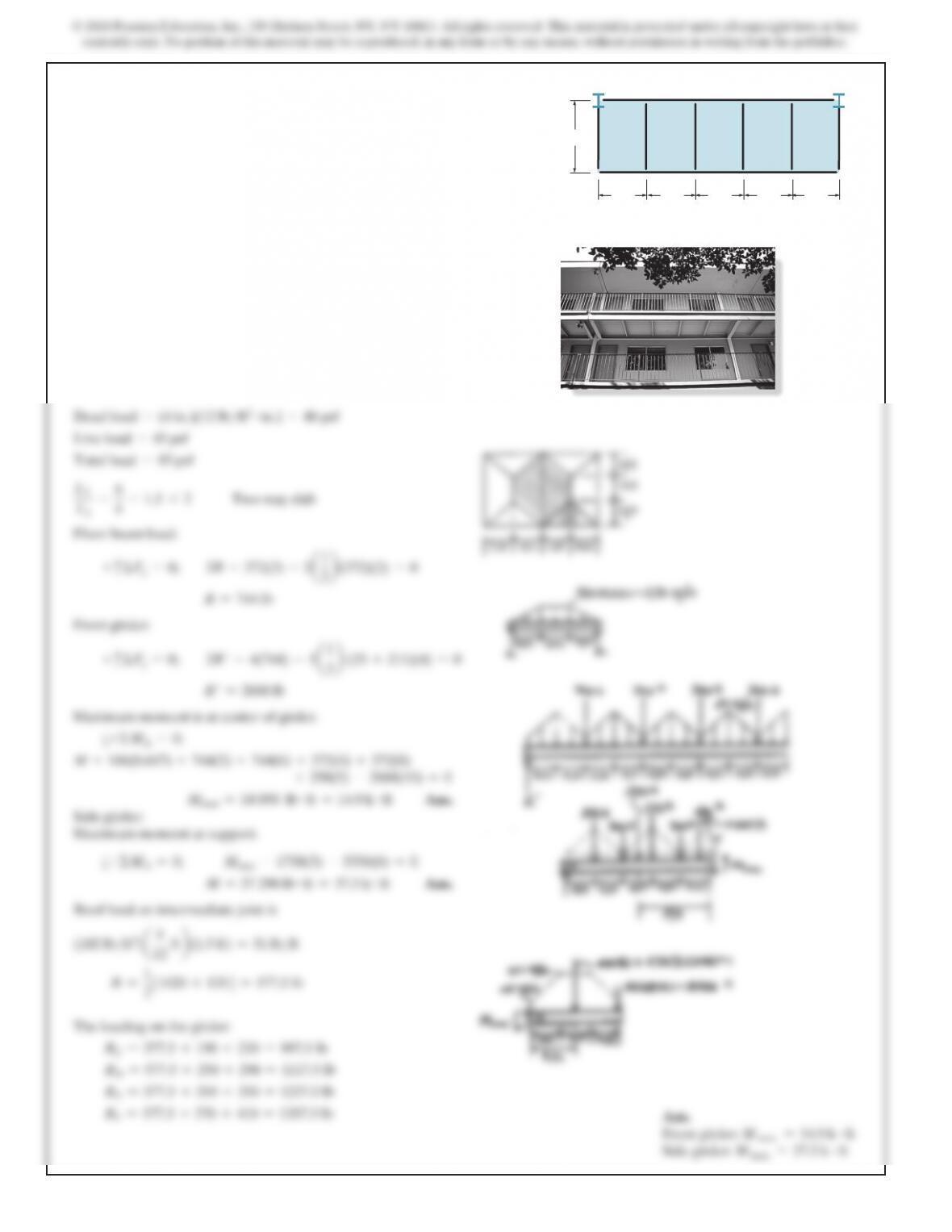
4–1P. The balcony located on the third floor of a motel is
shown in the photo. It is constructed using a 4-in.-thick concrete
(plain stone) slab which rests on the four simply supported
floor beams, two cantilevered side girders AB and HG, and the
front and rear girders. The idealized framing plan with average
dimensions is shown in the adjacent figure. According to local
code, the balcony live load is 45 psf. Draw the shear and
moment diagrams for the front girder BG and a side girder AB.
Assume the front girder is a channel that has a weight of
25
lb>ft
and the side girders are wide flange sections that have
a weight of
45
lb>ft.
Neglect the weight of the floor beams and
front railing. For this solution treat each of the five slabs as
two-way slabs.
A
BCDE F
H
G
6 ft
4 ft 4 ft 4 ft 4 ft 4 ft
SOLUTION
Dead load =(4 in.)(12 lb>ft2#in.) =48 psf
Live load =45 psf
Total load =93 psf
L
2
L1
=
6
4
=1.5 62
Two@way sla
b
Floor beam load:
+
c
ΣFy=0;
2R–372(2) –2
a1
2b
(372)(2) =
0
R=744 lb
Front girder:
+
c
ΣFy=0;
2R′–4(744) –5
a1
2b
(25 +211)(4) =
0
R′=2668 lb
Maximum moment is at center of girder.
a+ΣMA=0;
M+186(0.667) +744(2) +744(6) +372(4) +372(8)
+250(5) –2668(10) =0
Mmax =14 890 lb #ft =14.9 k #ft
Side girder:
Maximum moment at support.
a+ΣMA=0;
Mmax –1758(3) –5336(6) =0
M=37 290 lb #ft =37.3 k #ft
Roof load on intermediate joist is
(
102 lb
>
ft3)
a4
12
ft
b
(1.5 ft) =51 lb
>
f
t
R
=
1
23
1020 +135
4
=577.5 l
b
The loading on the girder:
RC=577.5 +190 +230 =997.5 lb
RD=577.5 +250 +290 =1117.5 lb
RE=577.5 +310 +350 =1237.5 lb
RF=577.5 +370 +410 =1357.5 lb
Ans.
Front girder:
M max =14.9 k #ft
Side girder:
M max =37.3 k #ft
Ans.
Ans.
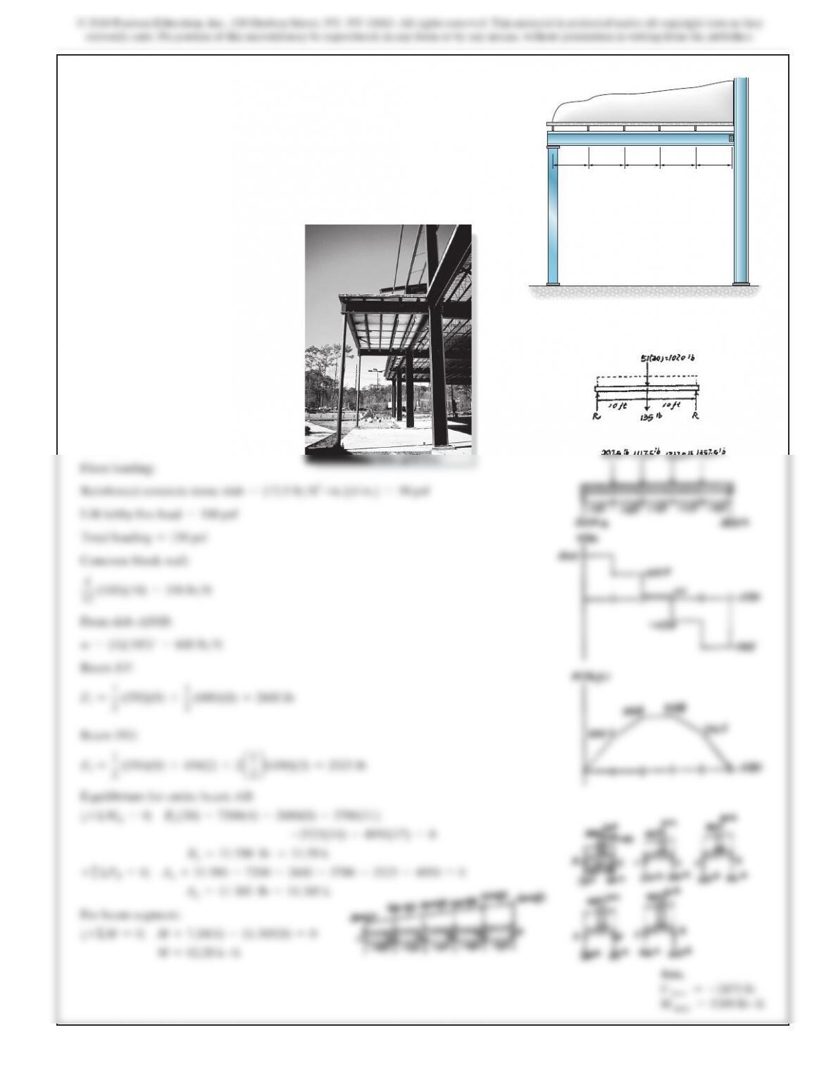
4–2P. The canopy shown in the photo provides shelter for the
entrance of a building. Consider all members to be simply
supported. The bar joists at C, D, E, F each have a weight of 135 lb
and are 20 ft long. The roof is 4 in. thick and is to be plain
lightweight concrete having a density of
102
lb>ft3.
Live load
caused by drifting snow is assumed to be trapezoidal, with 60psf
at the right (against the wall) and 20 psf at the left (overhang).
Assume the concrete slab is simply supported between the joists.
Draw the shear and moment diagrams for the side girder AB.
Neglect its weight.
SOLUTION
1.5 ft 1.5 ft 1.5 ft 1.5 ft 1.5 ft
A
CDEF
B