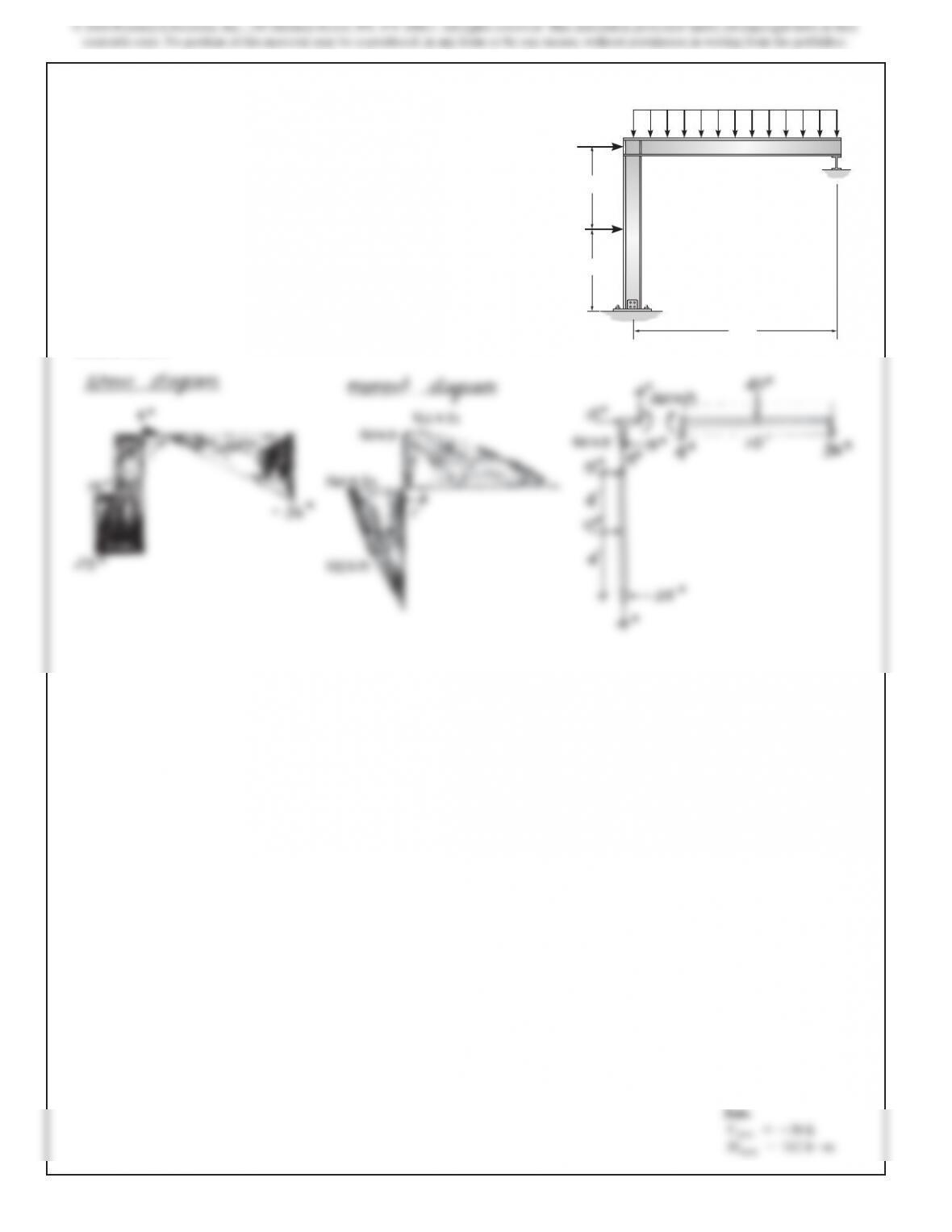
4–41. Draw the shear and moment diagrams for each member
of the frame. Assume the frame is pin connected at A and C is
a roller.
4 ft
15
k
4 k>ft
10 k
4 ft
10 ft
A
B
C
SOLUTION
168
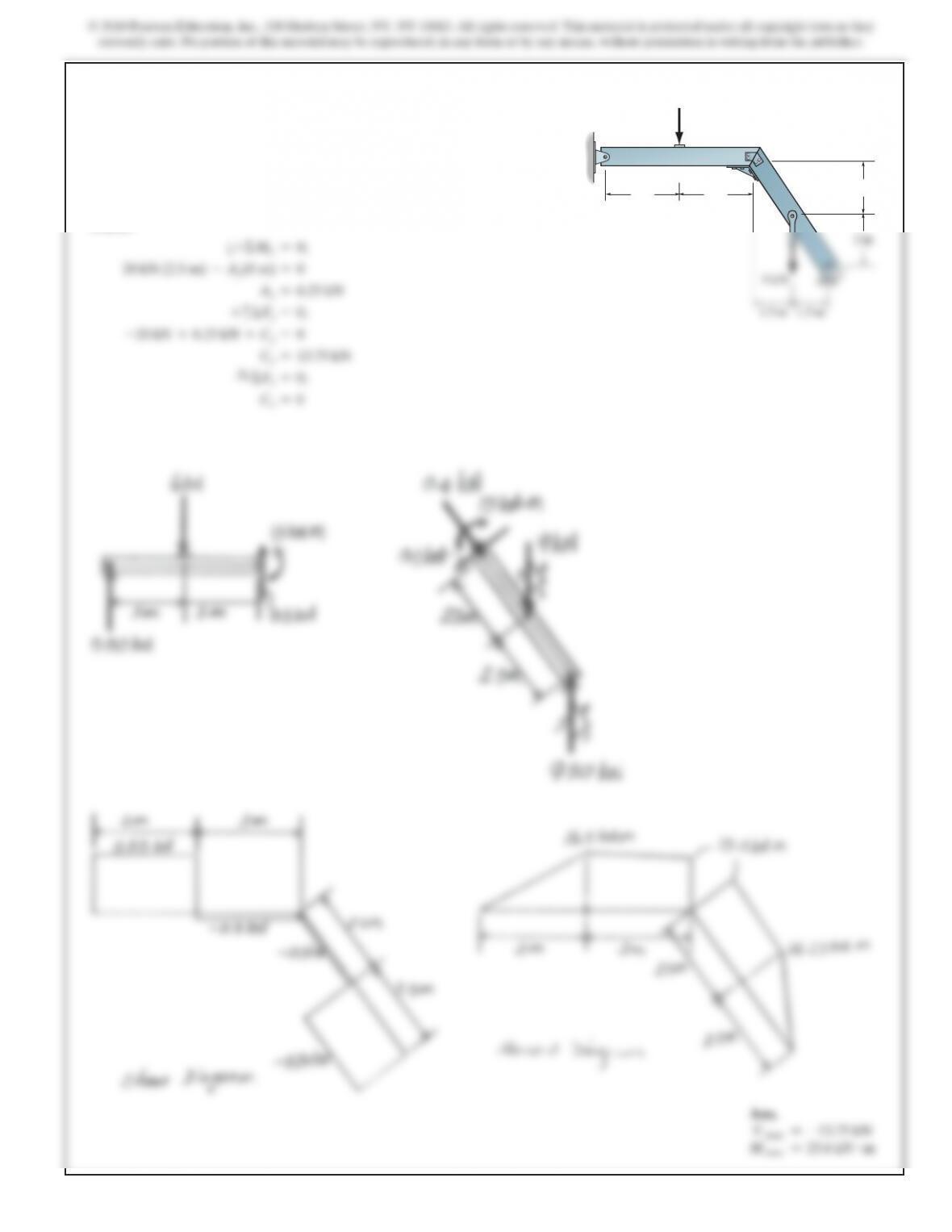
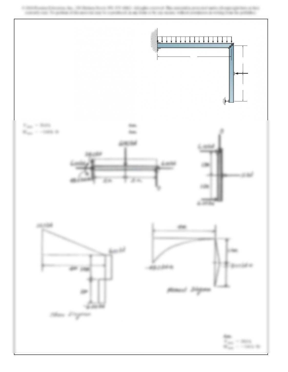
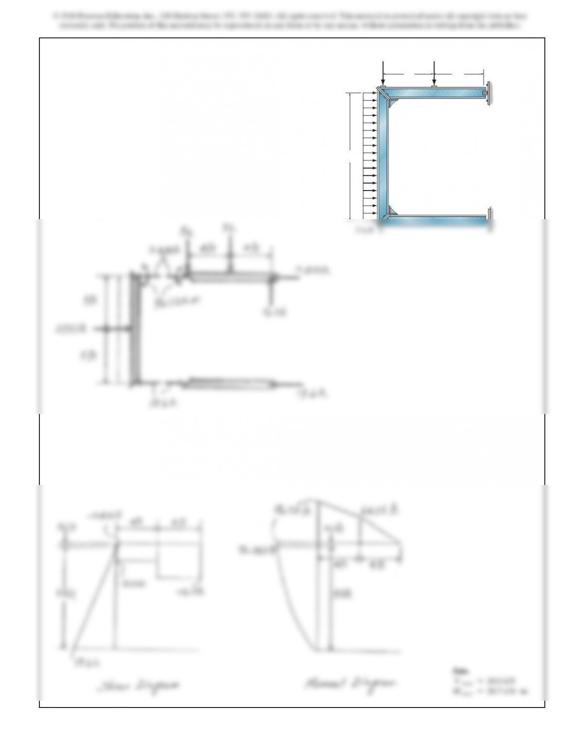
4–43. Draw the shear and moment diagrams for each member
of the frame. Assume A is fixed, the joint at B is a pin, and
support C is a roller.
SOLUTION
V max =20.0 k
Ans.
M max =–144 k #ft
Ans.
Ans.
V max =20.0 k
M max =–144 k #lb
B
A
C
6 kN>m
12 kN
4 m
1.5 m
1.5 m
169
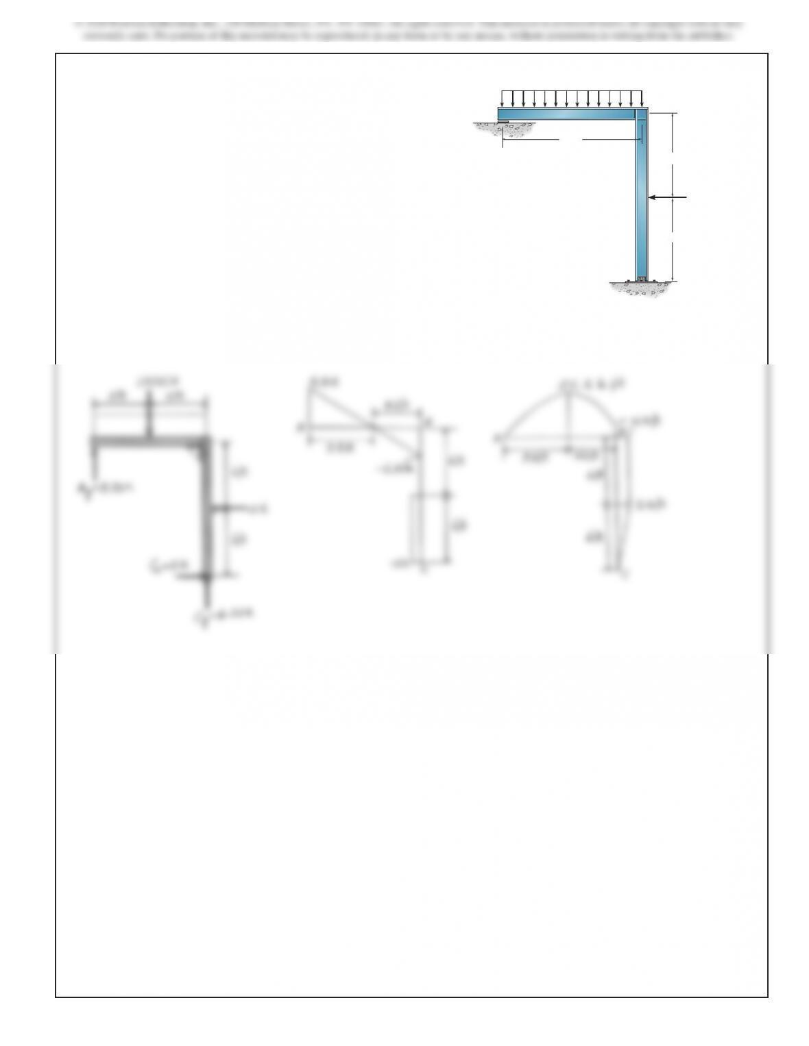
*4–44. Draw the shear and moment diagrams for each
member of the frame. Assume the frame is roller supported at
A and pin supported at C.AB
C
6 ft
6 ft
10 ft
1.5 k>ft
2
k
SOLUTION
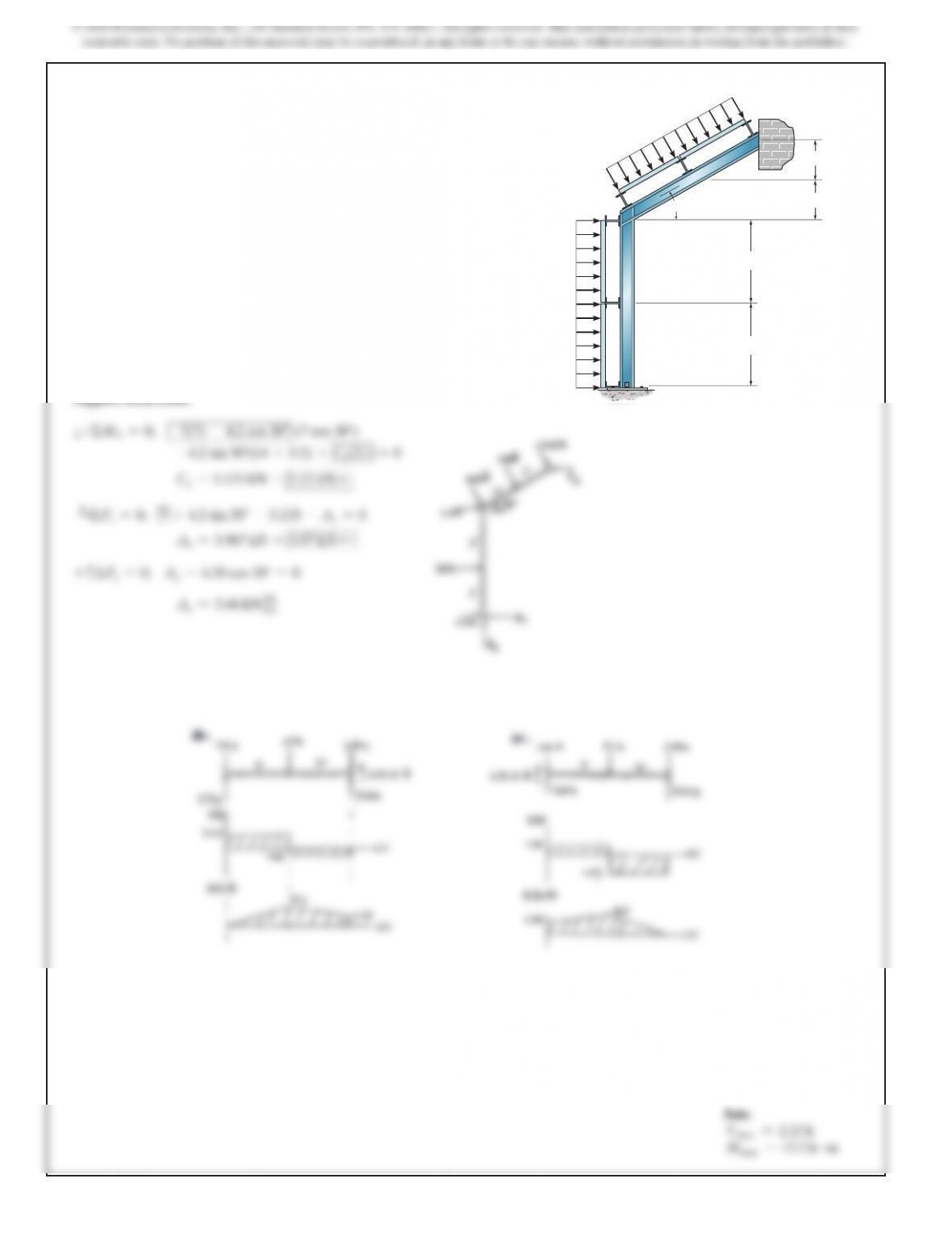
4–45. Draw the shear and moment diagrams for each member
of the frame. Assume the joint at A is a pin and support C is a
roller. The joint at B is fixed. The wind load is transferred to the
members at the girts and purlins from the simply supported
wall and roof segments.
SOLUTION
Support Reactions.
a+ΣMA=0;
–7(7) –4.2 cos 30° (7 cos 30°)
–4.2 sin 30°(14 +3.5) +Cx(21) =0
Cx=5.133 kN =5.13 kN d
S
+ΣFx=0;
7+4.2 sin 30°–5.133 –Ax=0
Ax=3.967 kN =3.97 kN d
+
c
ΣFy=0;
Ay–4.20 cos 30°=0
Ay=3.64 kN
c
300 lb>ft
500 lb>ft
A
B
C
30
7 ft
3.5 ft
3.5 ft
7 ft
8
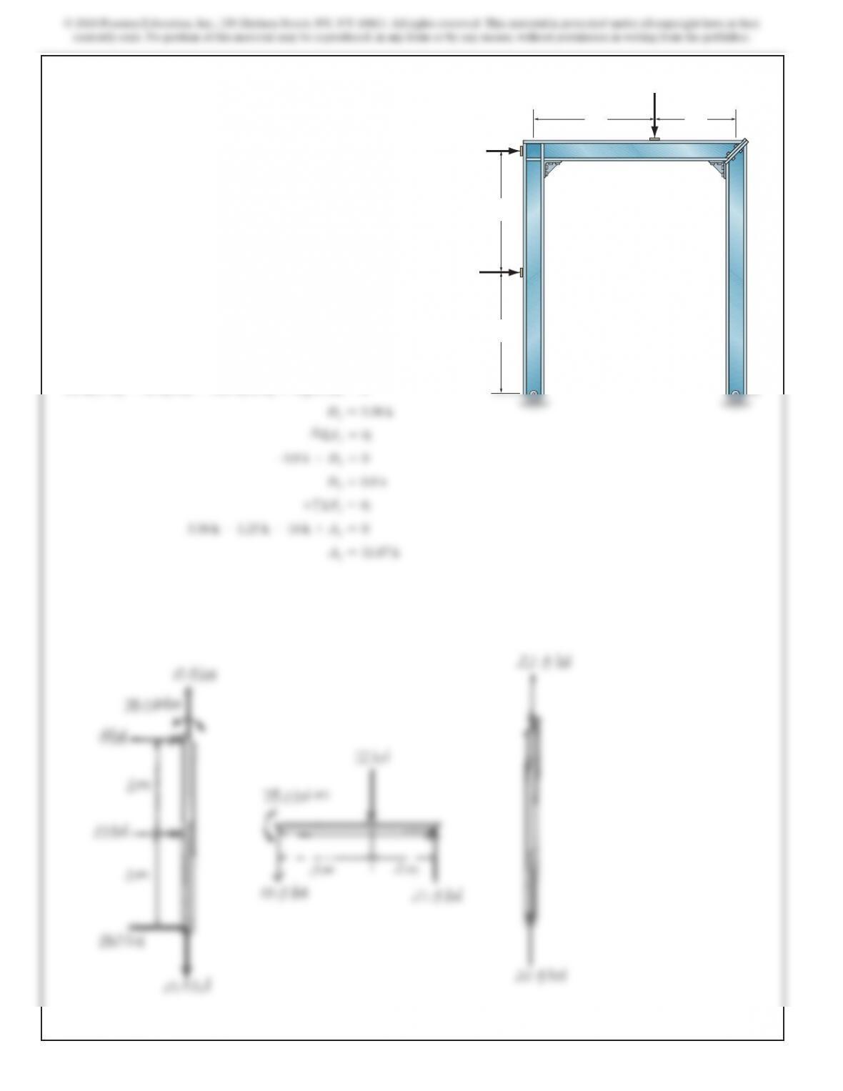
4–46. Draw the shear and moment diagrams for each member
of the frame. Assume A is a pin and D is a roller.
10 ft
4 ft 4 ft
8 k8 k
A
D
B
SOLUTION
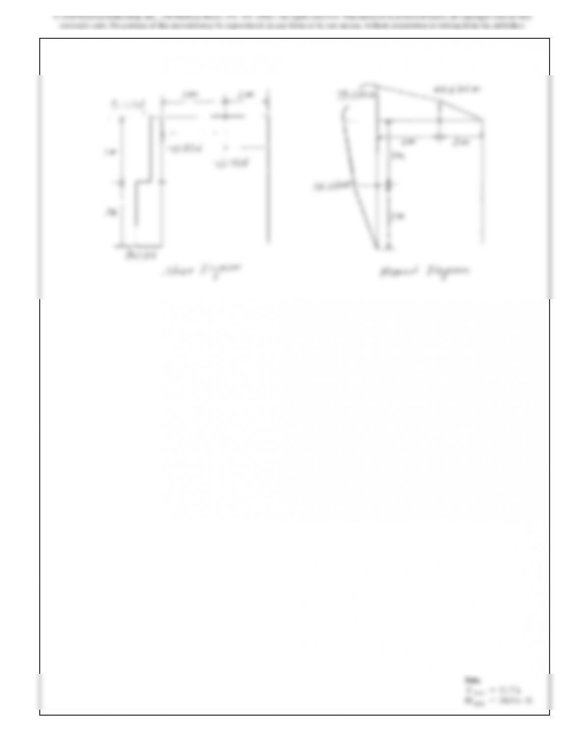
172
4–47. Draw the shear and moment diagrams for each member
of the frame. Assume joint B is rigid and C is pin connected.
A
D
BC
3 m
8 kN
10 kN
12 kN
3 m
3
m2
m
SOLUTION
a+ΣMA=0;
0.8 k(15 ft) –16 k(4 ft) –1.25 k(12 ft) +Dy(12 ft) =0
Dy=5.58 k
S
+ΣFx=0;
–0.8 k +Dx=0
Dx=0.8 k
+
c
ΣFy=0;
5.58 k –1.25 k –16 k +Ay=0
Ay=11.67 k
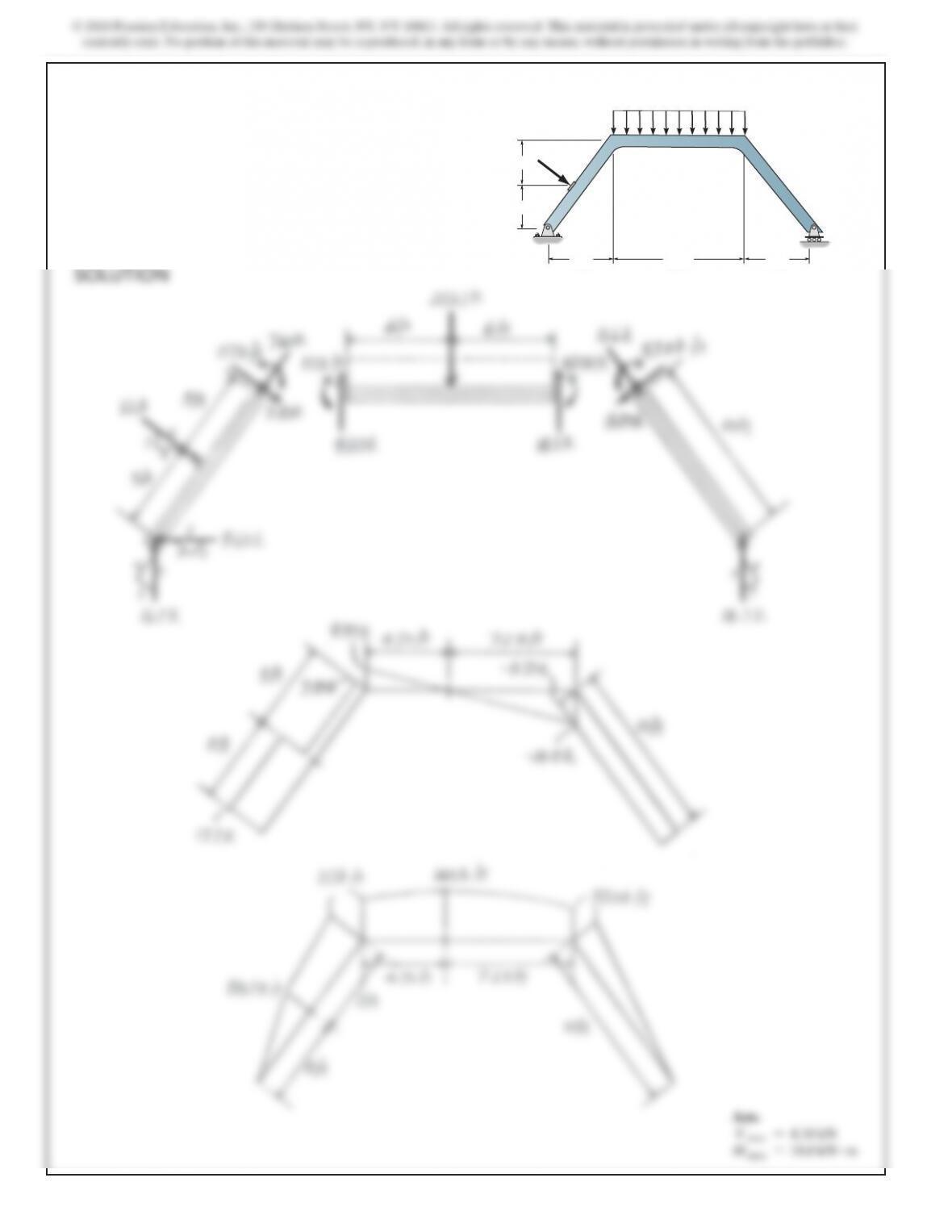
*4–48. Draw the shear and moment diagrams for each
member of the frame.
12 kN
12 ft6 ft
4 ft
6 ft
A
BC
D
4 ft
2 k>ft
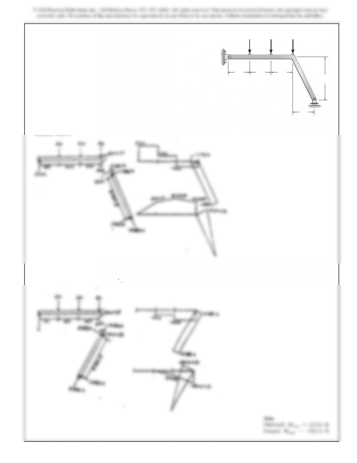
4–49. Leg BC on the framework can be designed to extend
either outward as shown, or inward with the support C
positioned below the center 2-k load. Draw the moment
diagrams for the frame in each case, to make a comparison of
the two designs.
4 ft 4 ft
2 k
4 ft
8 ft
4 ft
AB
C
2 k 2 k
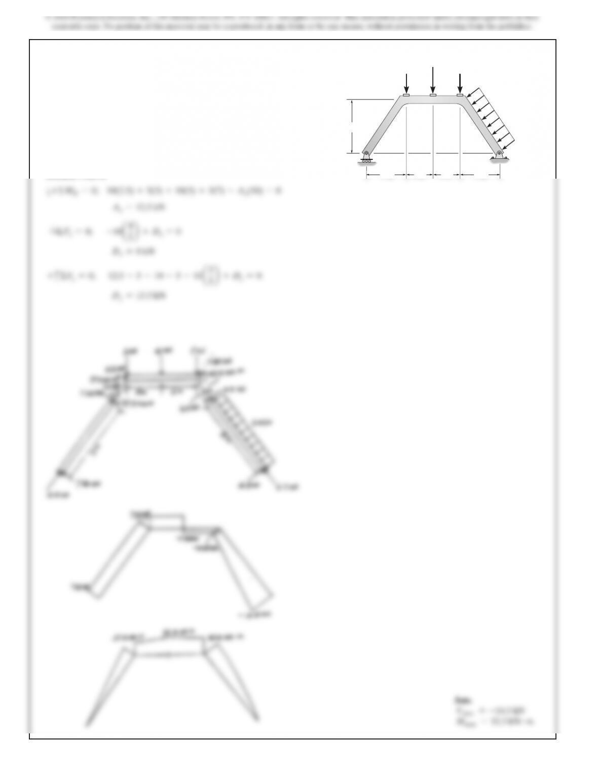
4–50. Draw the shear and moment diagrams for each member
of the frame.
a+ΣMD=0;
10(2.5) +5(3) +10(5) +5(7) –Ay(10) =0
Ay=12.5 kN
S
+ΣFx=0;
–10
a4
5b
+Dx=
0
Dx=8 kN
+
c
ΣFy=0;
12.5 –5–10 –5–10
a3
5b
+Dy=
0
Dy=13.5 kN
5 kN 5 kN
10 kN
2 kN>
m
3 m 3 m
4 m
2 m 2 m
A
BC
D
SOLUTION