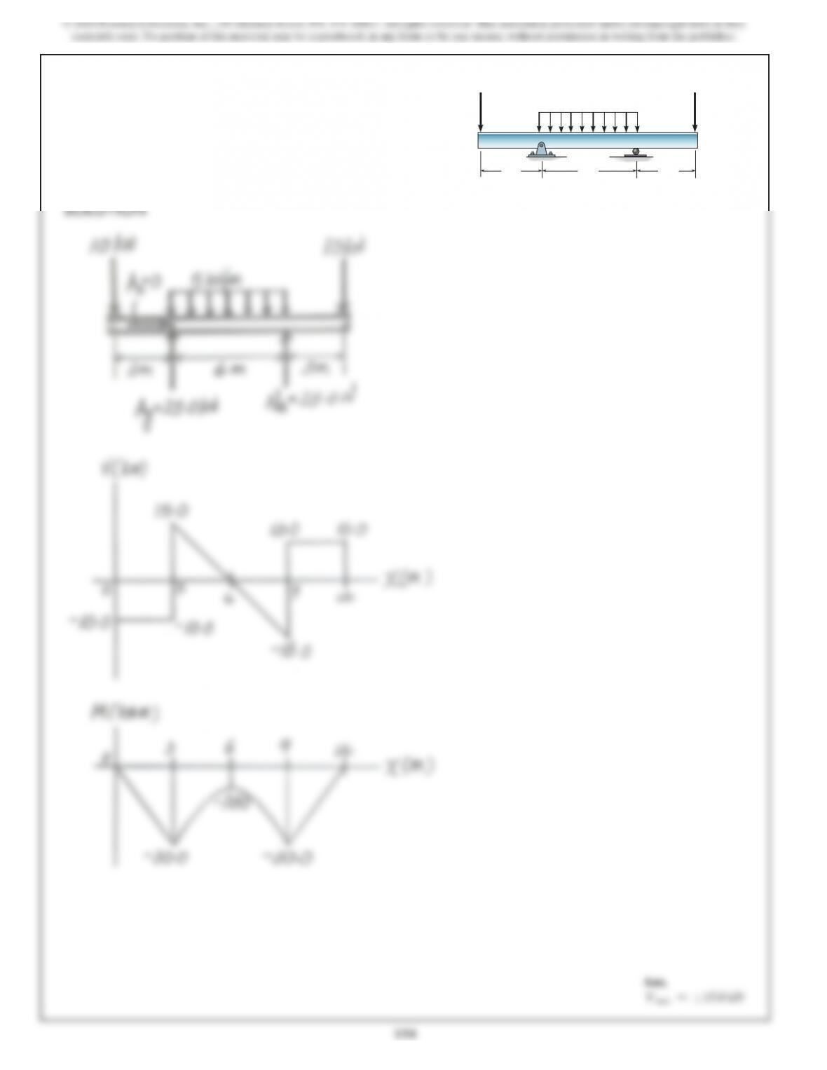
4–21. Determine the shear and moment in the beam a
function of x.
SOLUTION
1
200 lb
ft
B
x
4 ft 4 ft
150 lb>ft
6 ft
200 lb
ft
A
147
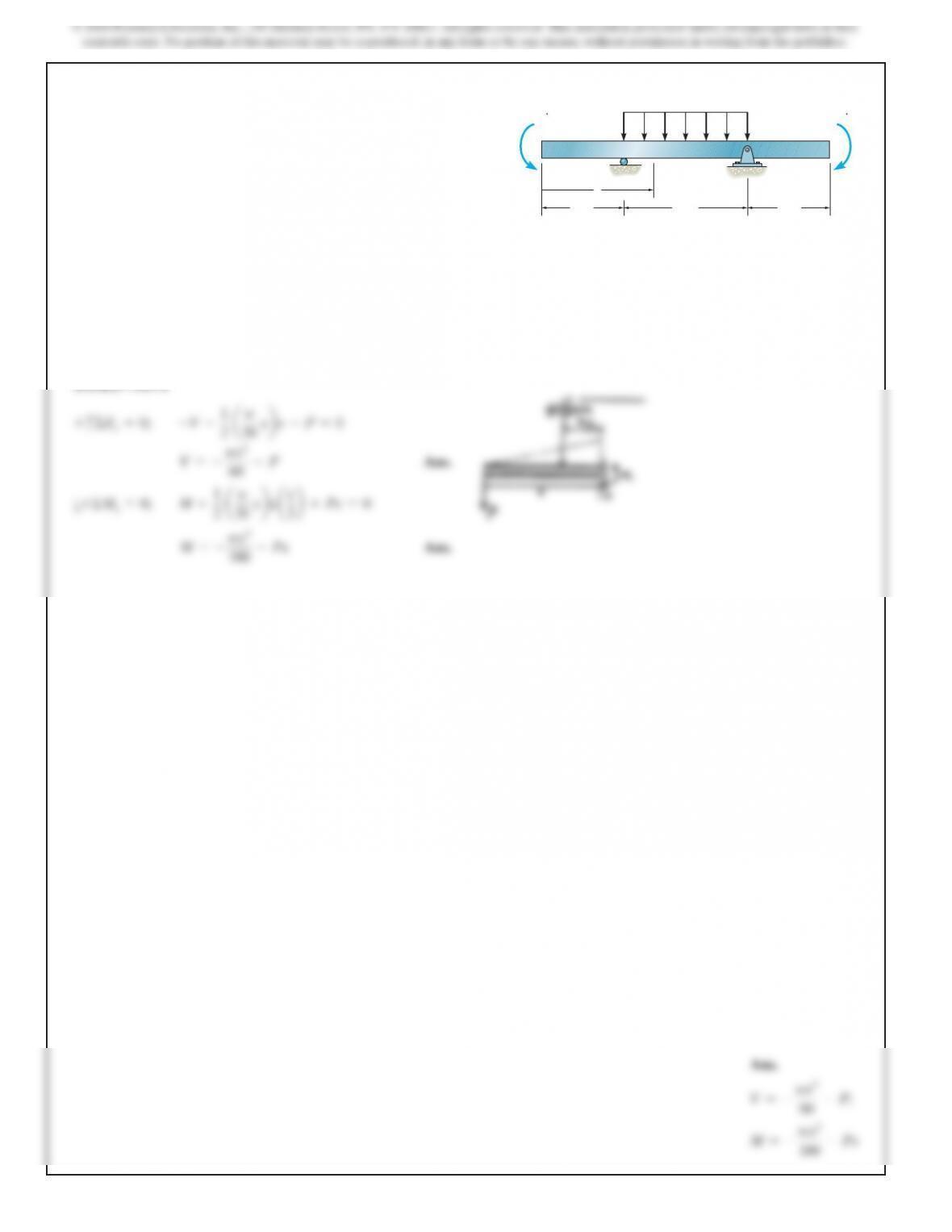
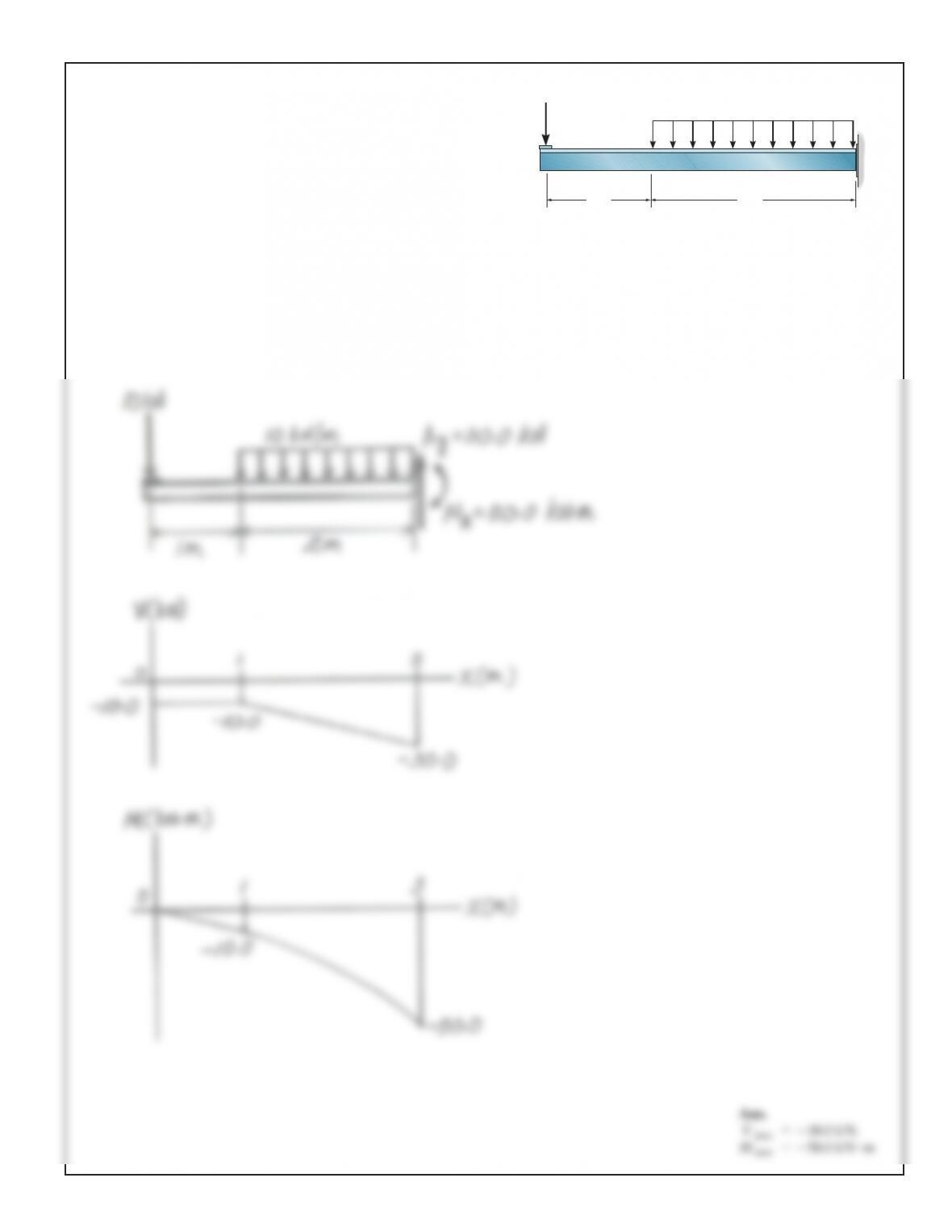
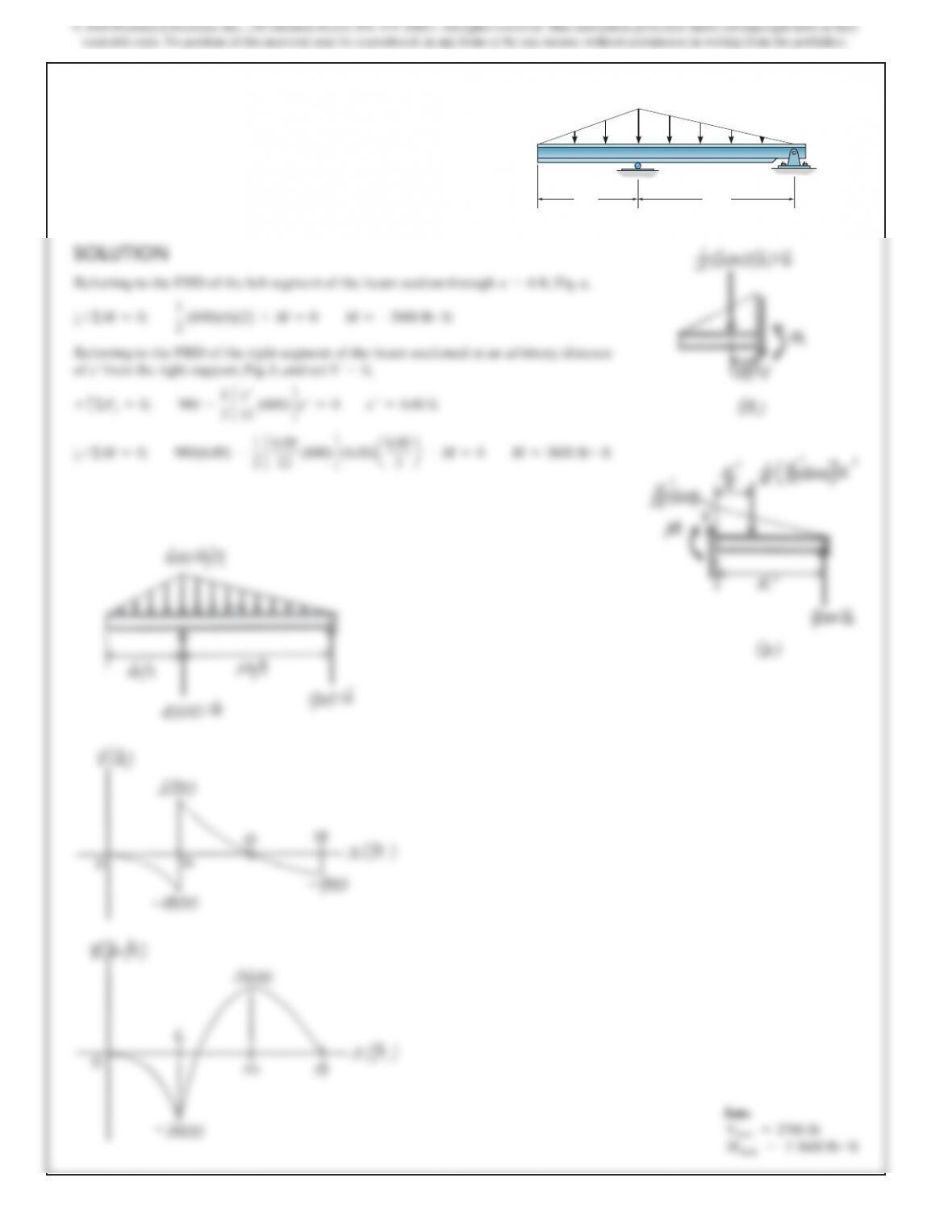
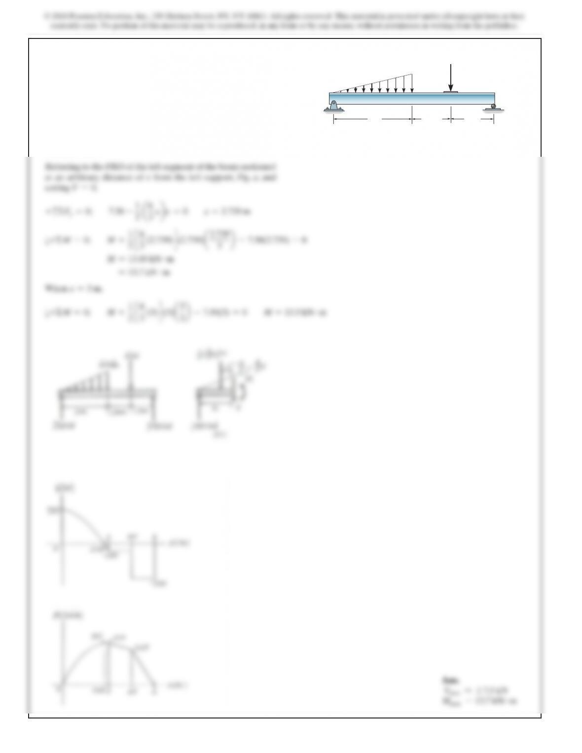
4–22. Draw the shear and moment diagrams for the beam
and determine the shear and moment in the beam a function
of x, where
4
ft 6x610
ft
.
SOLUTION
+
c
ΣFy=0;
–150(x–4) –V+450 =0
Ans.
V=1050 –150x
M=–75x2+1050x–3200
200 lb
ft
B
x
4 ft 4 ft
150 lb
>
ft
6 ft
200 lb
ft
A
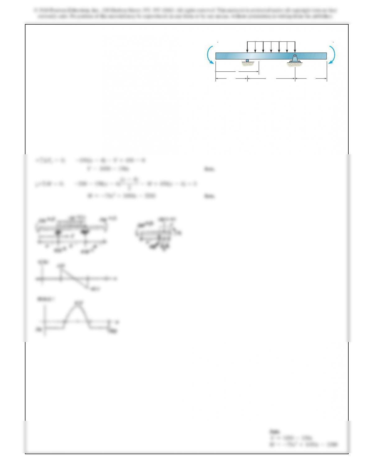
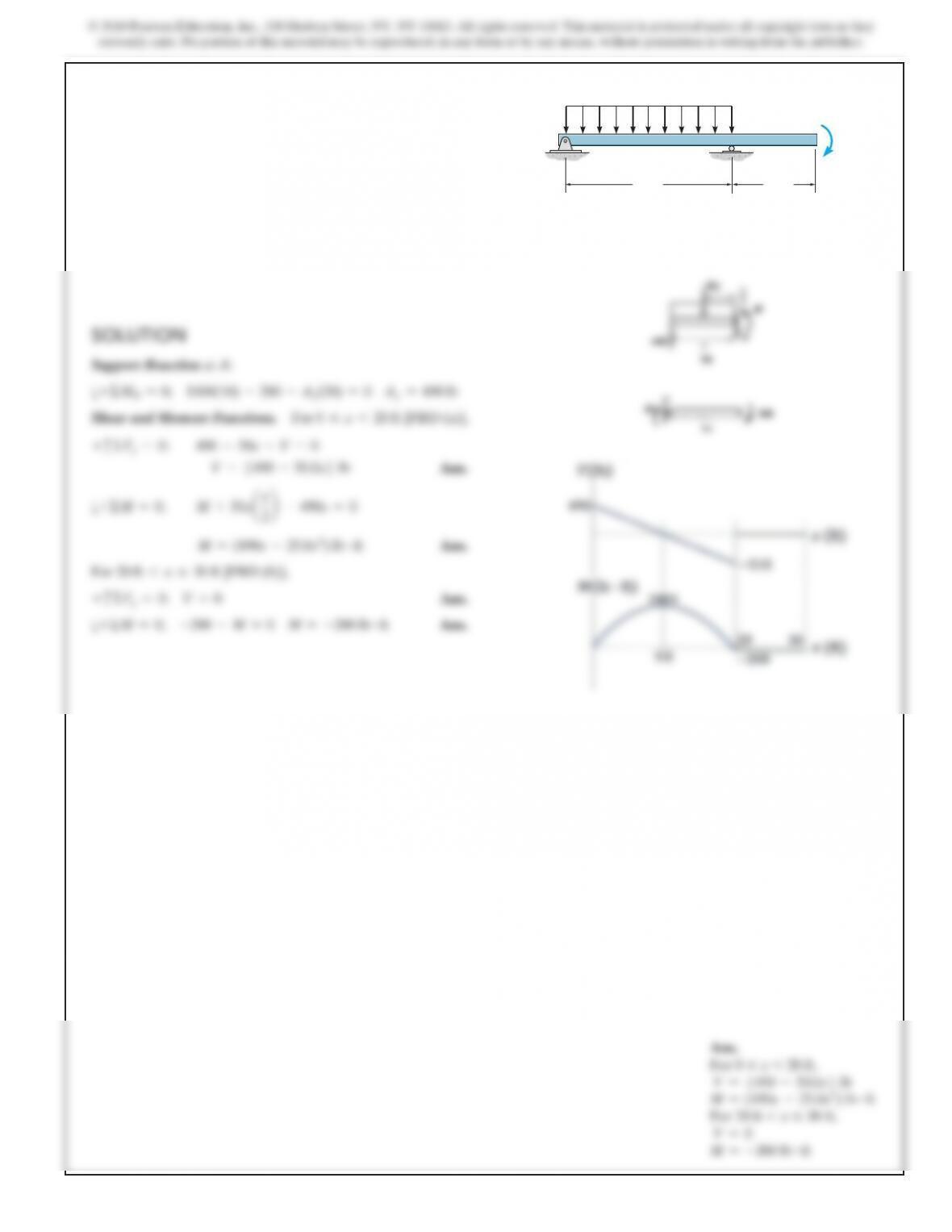
4–23. Draw the shear and moment diagrams for the beam
and determine the shear and moment a function of x.
SOLUTION
Support Reactions. As shown on FBD.
Shear and Moment Functions.
3 m 3 m
x
BA
200 N>m
400 N>m
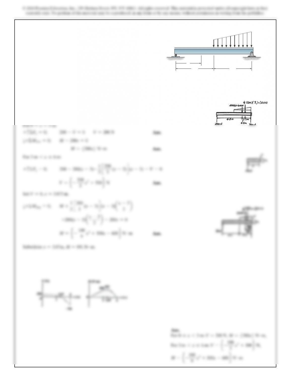
*4–24. Draw the shear and moment diagrams for the beam.
SOLUTION
8 ft
A
B
500 lb
200 lb 30
0 lb
8 ft 8 ft
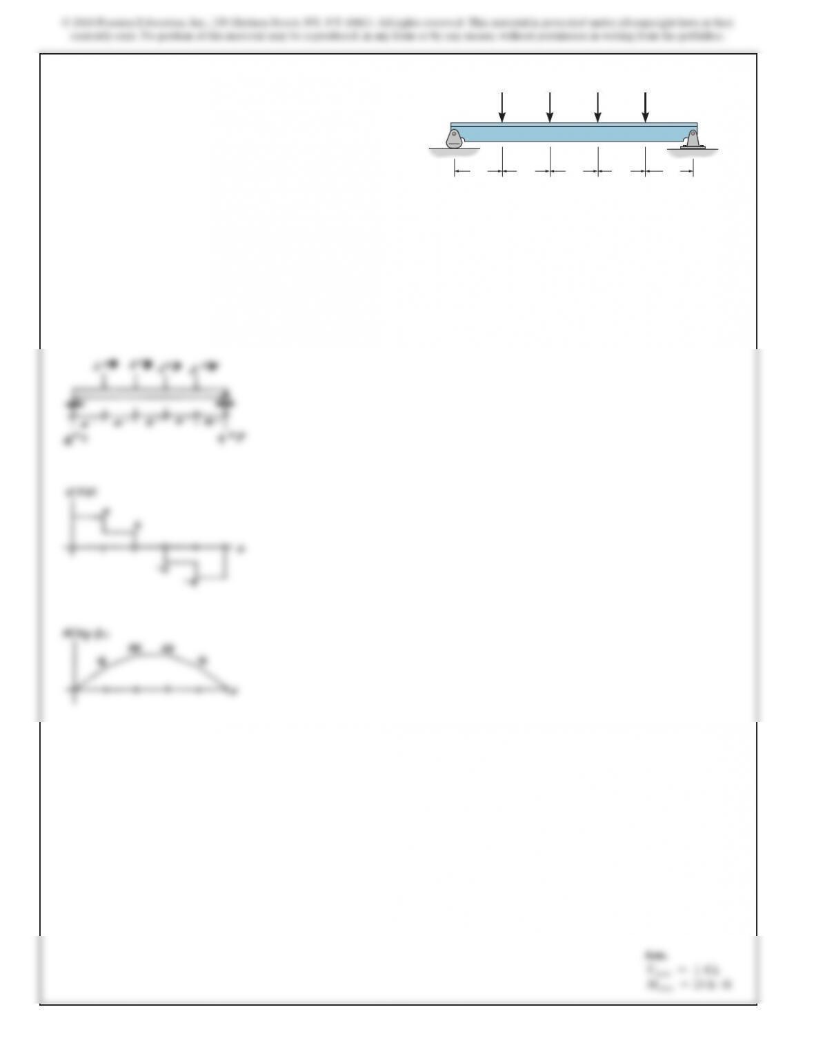
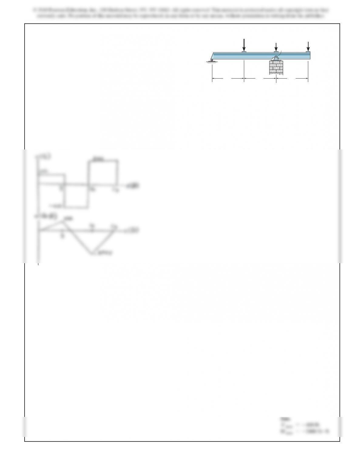
4–25. Draw the shear and moment diagrams for the beam.
4 ft4 ft4 ft4 ft4 ft
2 k2 k2 k
4 ft4 ft4 ft4 ft4 ft
A
2 k
SOLUTION
151
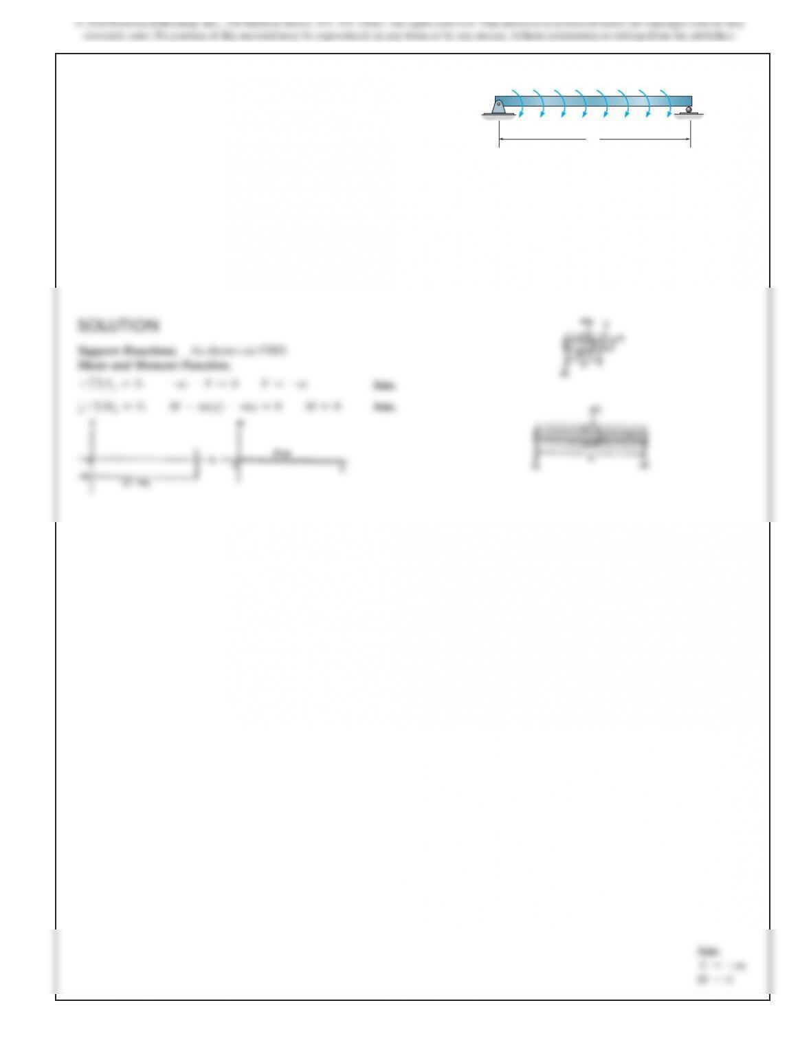
4–26. The beam is subjected to the uniformly distributed
moment m (moment/length). Draw the shear and moment
diagrams for the beam.
L
B
A
m
Ans.
V=–m
M=0
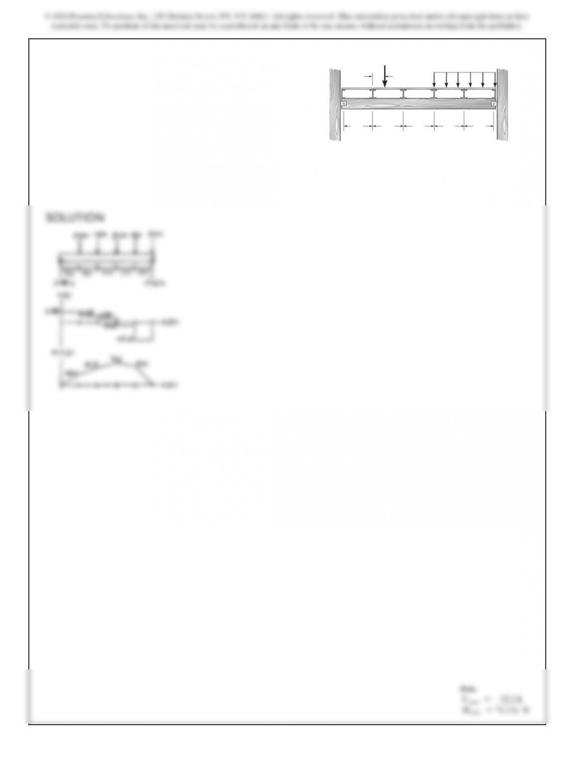
4–27. The flooring system for a building consists of a girder
that supports laterally running floor beams, which in turn
support the longitudinal simply supported floor slabs. Draw
the shear and moment diagrams for the girder. Assume the
girder is simply supported.
5 ft 5 ft 5 ft 5 ft 5 ft
2 ft
4 k
AB
2 k>ft
153
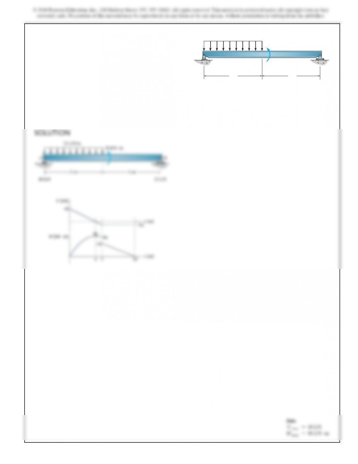
*4–28. Draw the shear and moment diagrams for the beam.
5 m 5 m
30 kN m
B
12 kN>m
A
?
Ans.
V max =48 kN
M max =96 kN #m
5 m 5 m
30 kN m
B
12 kN/m
48 kN 12 kN
A
?
SOLUTION
© 2018 Pearson Education, Inc., 330 Hudson Street, NY, NY 10013. All rights reserved. This material is protected under all copyright laws as they
currently exist. No portion of this material may be reproduced, in any form or by any means, without permission in writing from the publisher.
4–29. Draw the shear and moment diagrams for the beam.
AB
3 m6 m
3 m
5 kN>m
10 kN 10 kN
© 2018 Pearson Education, Inc., 330 Hudson Street, NY, NY 10013. All rights reserved. This material is protected under all copyright laws as they
currently exist. No portion of this material may be reproduced, in any form or by any means, without permission in writing from the publisher.
4–30. Draw the shear and moment diagrams for the beam.
1 m 2 m
A
10 kN
10 kN>m
SOLUTION
156
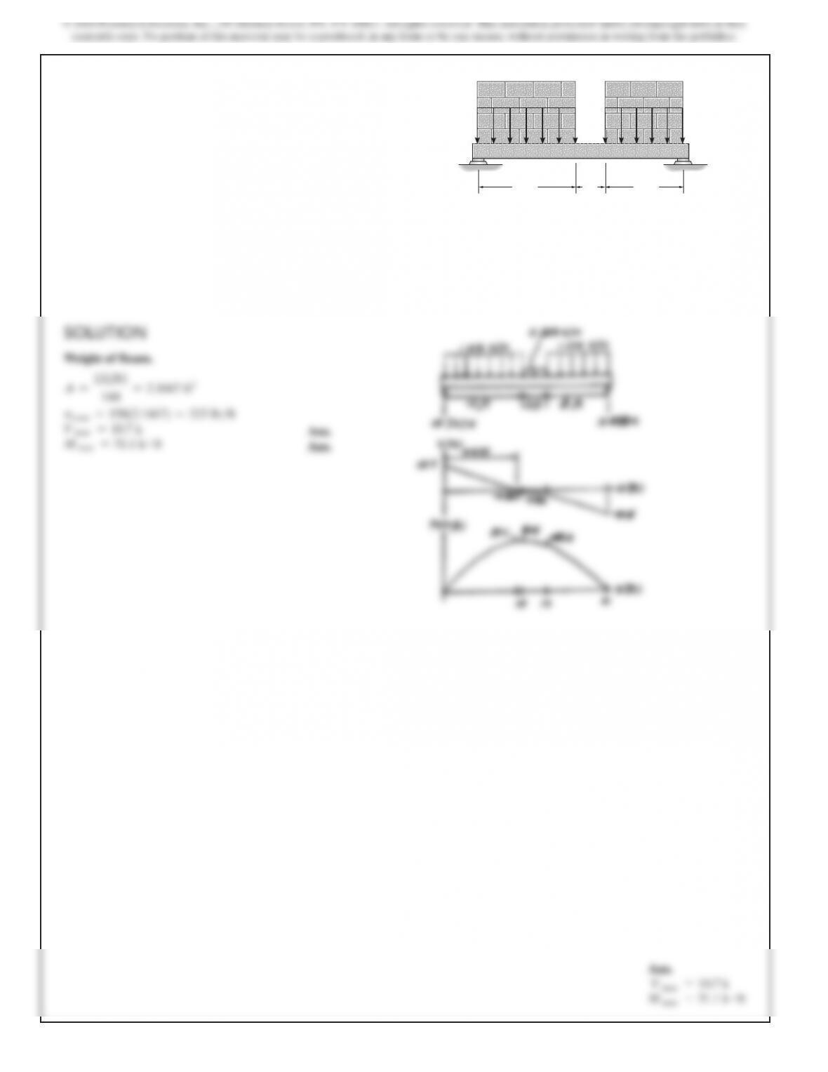
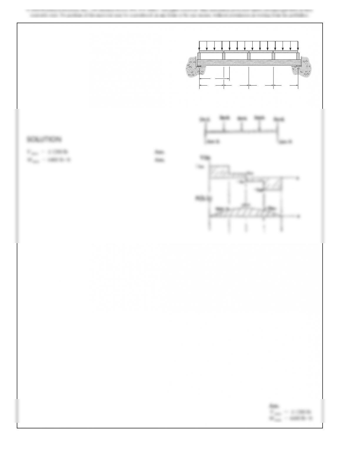
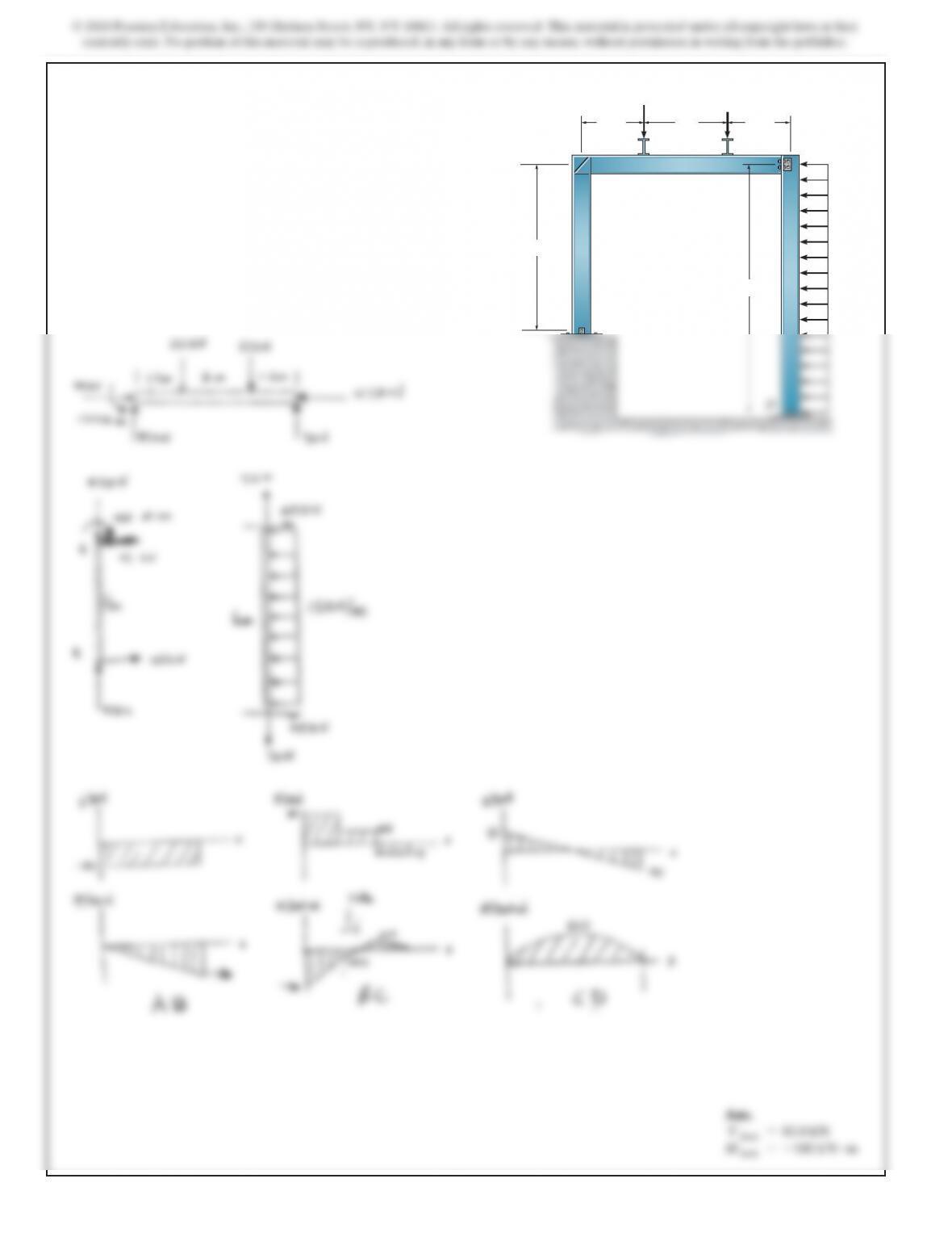
4–31. The concrete beam supports the wall, which subjects
the beam to the uniform loading shown. The beam itself has
cross-sectional dimensions of 12 in. by 26 in. and is made from
concrete having a specific weight of
g=150
lb>ft3
. Draw the
shear and moment diagrams for the beam and specify the
maximum moment in the beam. Neglect the weight of the steel
reinforcement in the beam.
10 ft 8 ft3 ft
800 lb
>ft 800 lb>
ft
Ans.
V max =10.7 k
M max =51.1 k #ft
*4–32. Draw the shear and moment diagrams for the compound
beam.
B
ACD
2 m 1 m 1 m
5 kN>m
SOLUTION
Support Reactions.
4–33. Draw the shear and moment diagrams for the beam.
6 ft 12 ft
A
B
600 lb>ft
159
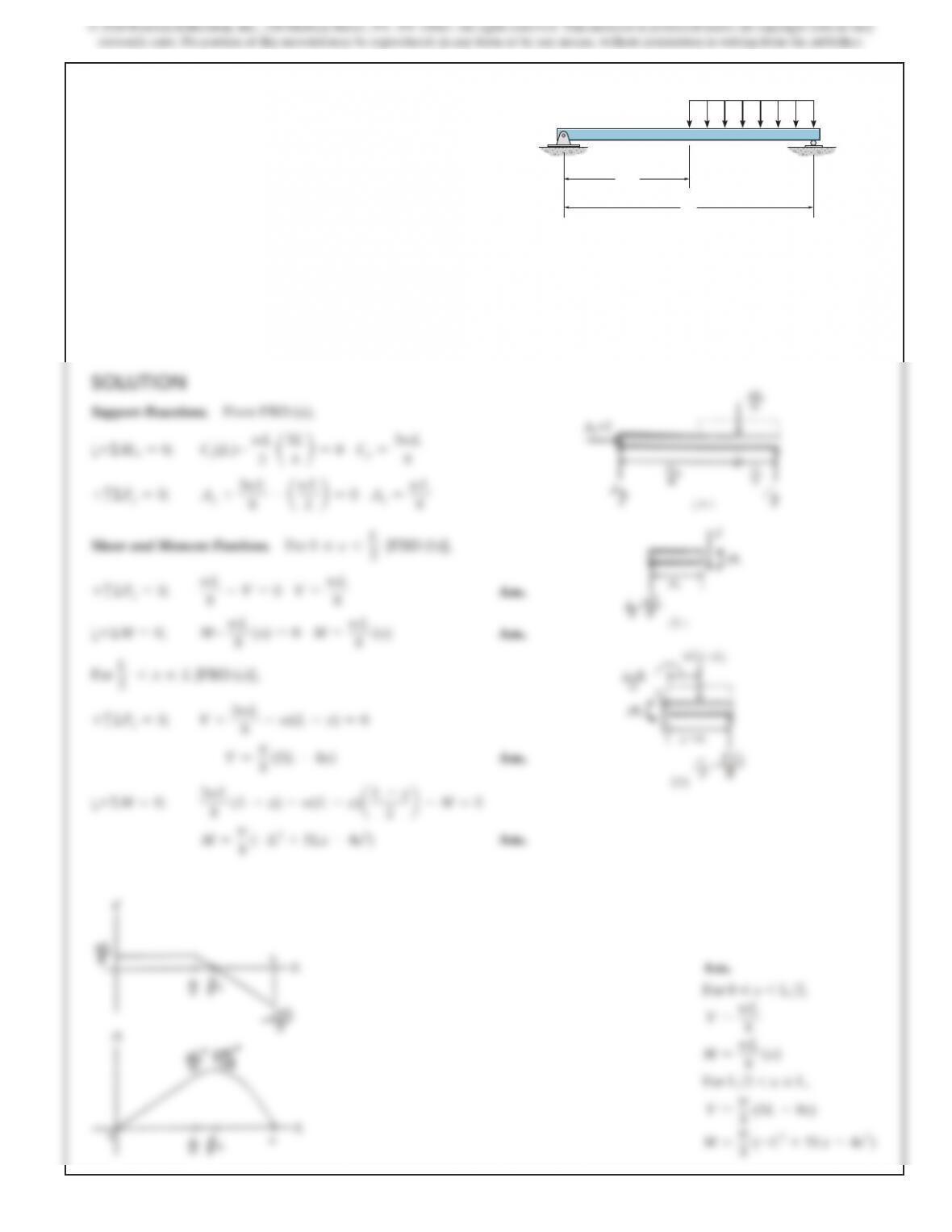
4–34. Draw the shear and moment diagrams for the beam.
C
w
A
B
L
L
––
2
w
8
Ans.
For 0 … x 6 L>2
,
V=
wL
8
M
=
wL
8
(x)
For L>2 6 x … L
,
V=
w
8
(5L–8x)
M
=
w
8
(–L2+5Lx –4x2
)
4–35. Draw the shear and moment diagrams for the beam.
x
4 ft 4 ft 4 ft 4 ft
200 lb>ft
CD EFG
A B
*4–36. Draw the shear and moment diagrams for the
compound beam.
BA
6 ft
1
50 lb
>
ft 150 lb
>ft
3 ft
C
4–37. Draw the shear and moment diagrams for the beam.
A
B
6 kN>m
3 m 1.5 m
1.5 m
6 kN
SOLUTION
163
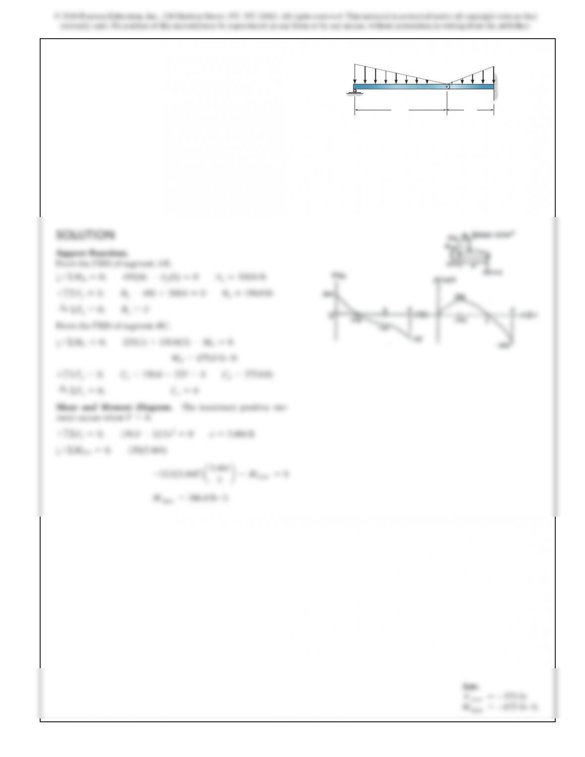
4–38. Draw the shear and bending-moment diagrams for the
beam.
C
A
B
20 ft 10 ft
50 lb
>
ft
200 lb
ft
?
Ans.
For 0 … x 6 20 ft,
V=5490 –50.0x6 lb
M=(490x–25.0x2) lb #ft
For 20 ft 6 x … 30 ft,
V=0
M=–200 lb #ft
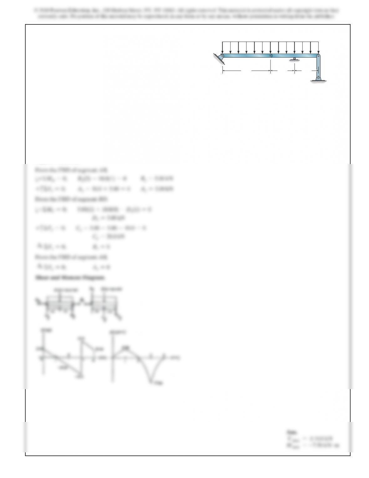
4–39. Draw the shear and moment diagrams for each of the
three members of the frame. Assume the frame is pin connected
at A, C, and D and there is a fixed joint at B.
15 kN>
m
50 kN
40 kN
A
BC
1.5 m 1.5 m2 m
4 m
6 m
SOLUTION
165
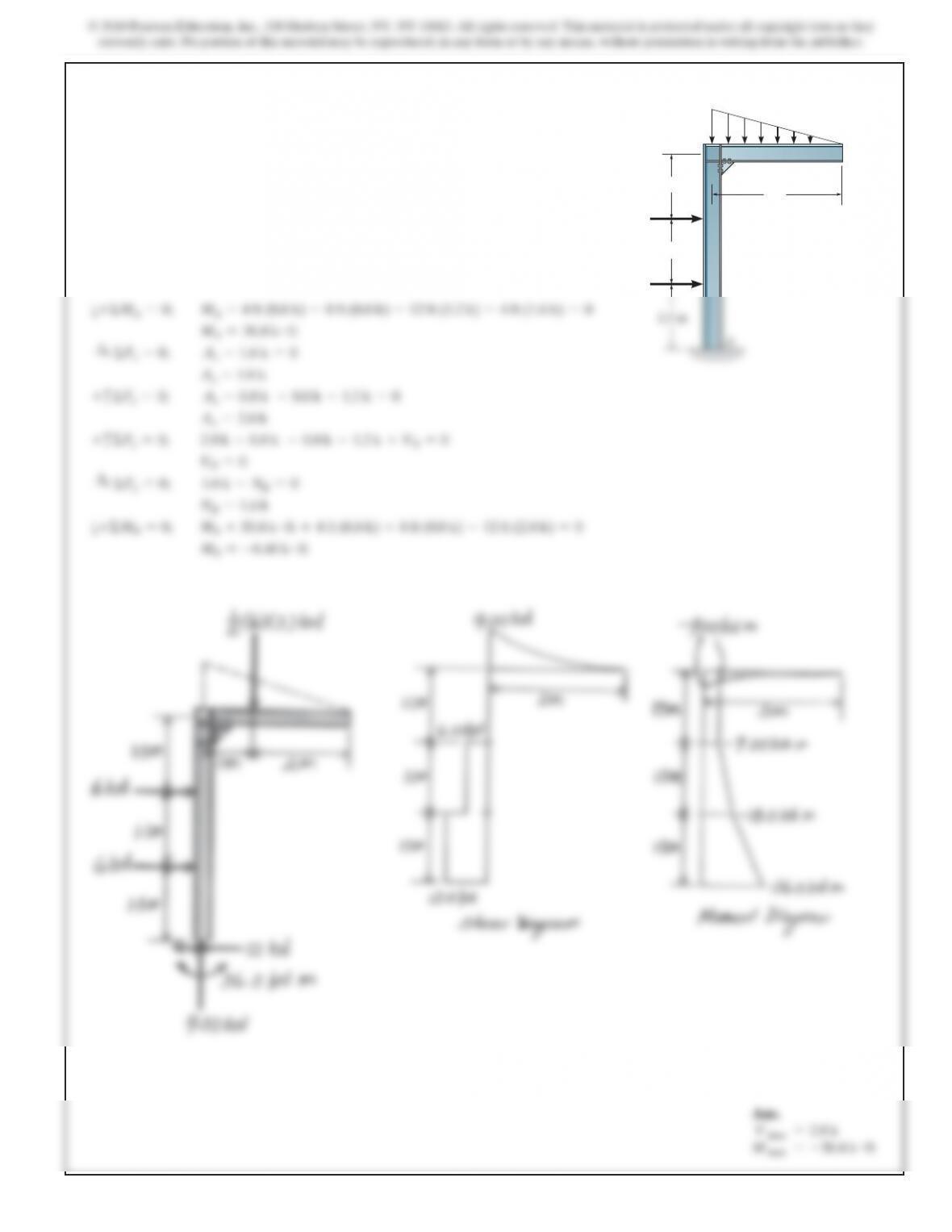
*4–40. Draw the shear and moment diagrams for each member of
the frame.
6 kN>m
1.5 m
1.5 m
B
C
3 m
6 kN
6 kN
SOLUTION
a+ΣMA=0;
MA–4 ft (0.8 k) –8 ft (0.8 k) –12 ft (1.2 k) –4 ft (1.6 k) =0
MA=30.4 k #ft
S
+ΣFx–0;
Ax–1.6 k =0
Ax–1.6 k
+
c
ΣFy=0;
Ay–0.8 k –0.8 k –1.2 k =0
Ay=2.8 k
+
c
ΣFy=0;
2.8 k –0.8 k –0.8 k –1.2 k +VB=0
VB=0
S
+ΣFx=0;
1.6 k –NB=0
NB=1.6 k
a+ΣMB=0;
MB+30.4 k #ft +4 ft (0.8 k) +8 ft (0.8 k) –12 ft (2.8 k) =0
MB=–6.40 k #ft
Ans.
V max =2.8 k
M max =–30.4 k #ft