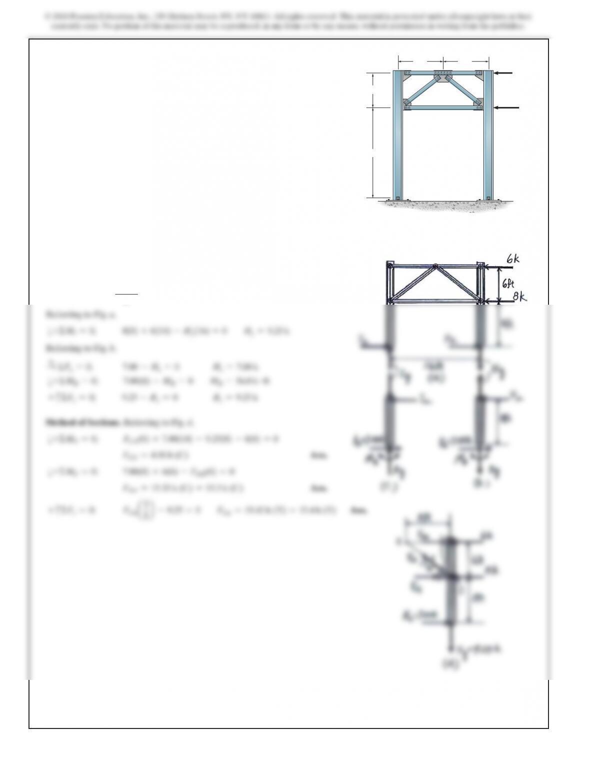
SOLUTION
Support Reactions. Assume that zero moment occurs at the mid-height of
the column between B and C (point H) and between A and G (point I).
Also, the horizontal reaction corresponents at A and B are equal. Then
A
x=Bx=
6+8
2
=7.00
k
12–26. Draw (approximately) the moment diagram for
column BCD of the portal. Assume all the members of the
truss to be pin connected at their ends. The columns are fixed
at A and B. Also determine the force in all the truss members.
8 ft 8 ft
6 ft
16 ft
AB
D
G
F
C
E
6 k
8
k
600
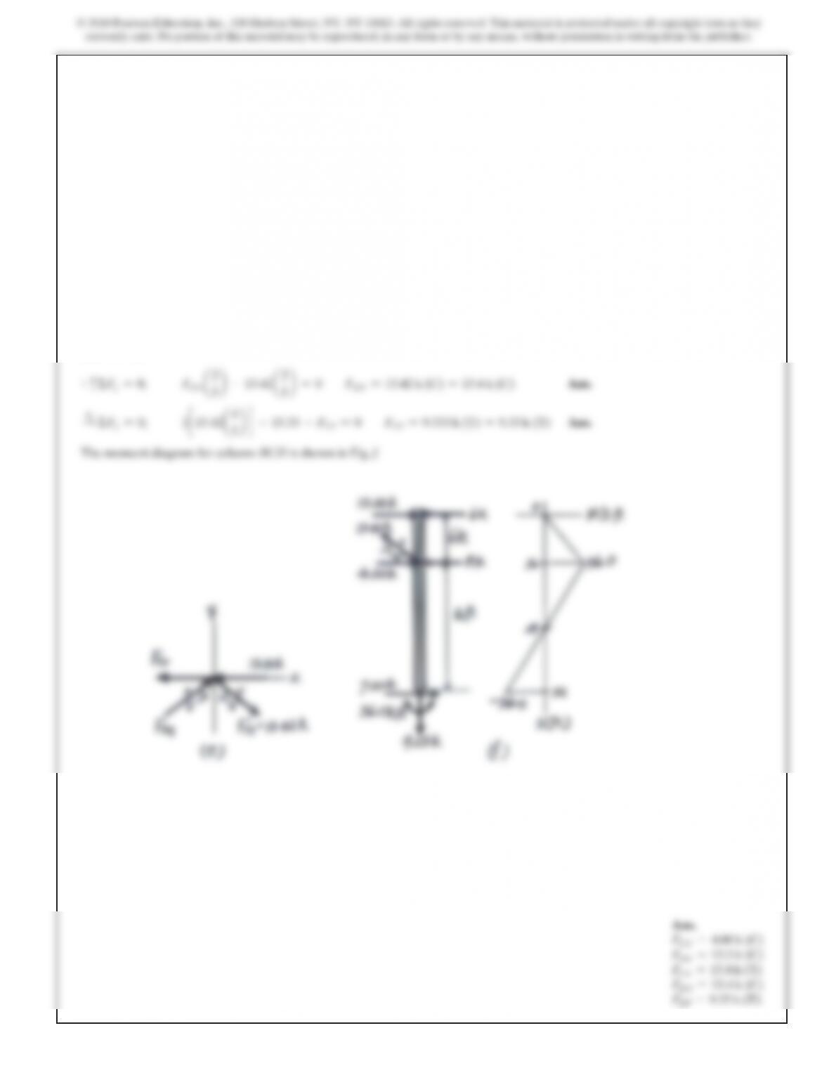
SOLUTION
By inspection of joints E and F,
FEG =0
Ans.
FFI =0
Ans.
+
c
ΣFy=0;
FCE(cos
45°)–7.60 =0
FCE =10.748
k=10.7
k
(T)
Ans.
a+ΣMC=0;
FGH(10) –8(10) –6.0(6) =0
FGH =11.6
k
(C)
Ans.
+
SΣFx=0;
–FCD –6–11.6 +8+4+10.748(sin
45°)=0
FCD =2.00
k
(C)
Ans.
MA=MB=36.0
k#ftB
Ans.
Ax=Bx=6.00
kd
Ans.
Ay=7.6
kT
By=7.6
k
c
Ans.
Joint E:
+ QΣFx=0;
FEH =10.7
k
(T)
Ans.
Joint H:
+
c
ΣFy=0;
FHF
sin
45°–10.748
sin
45°=0
FHF =10.748 =10.7
k
(C)
Ans.
+
SΣFx=0;
FHI +11.6 –2(10.748)(cos 45°)=0
FHI =3.60
k
(T)
Ans.
Joint F:
a + ΣFy=0;
FFD =10.7
k
(C)
Ans. Ans.
FCE =10.7
k
(T)
FGH =11.6
k
(C)
FCD =2.00
k
(C)
MA=36.0
k#ftB
Ax=6.00
kd
Ay=7.6
kT
By=7.6
k
c
FEH =10.7
k
(T)
FHF =10.7
k
(C)
FHI =3.60
k
(T)
FFD =10.7
k
(C)
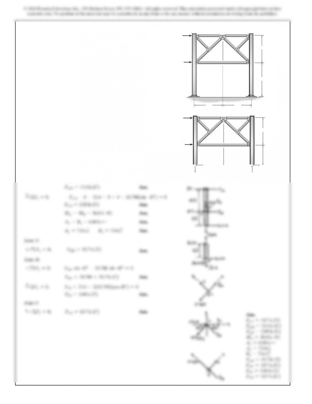
12–27. Determine (approximately) the force in each truss
member of the portal frame. Also find the reactions at the fixed
column supports A and B. Assume all members of
the truss to be pin connected at their ends.
10 ft
6 ft
6 k
7.6 k
6 k
7.6 k
8
k
4 k
C
E
G
H
I
F
D
B
10 ft
A
12 ft
8
k
4
k
C
E
G
H
I
F
D
10 ft 10 ft
SOLUTION
Support Reactions. Assume that the zero moment occurs at the mid-
height of the column between A and I (point M) and between B and
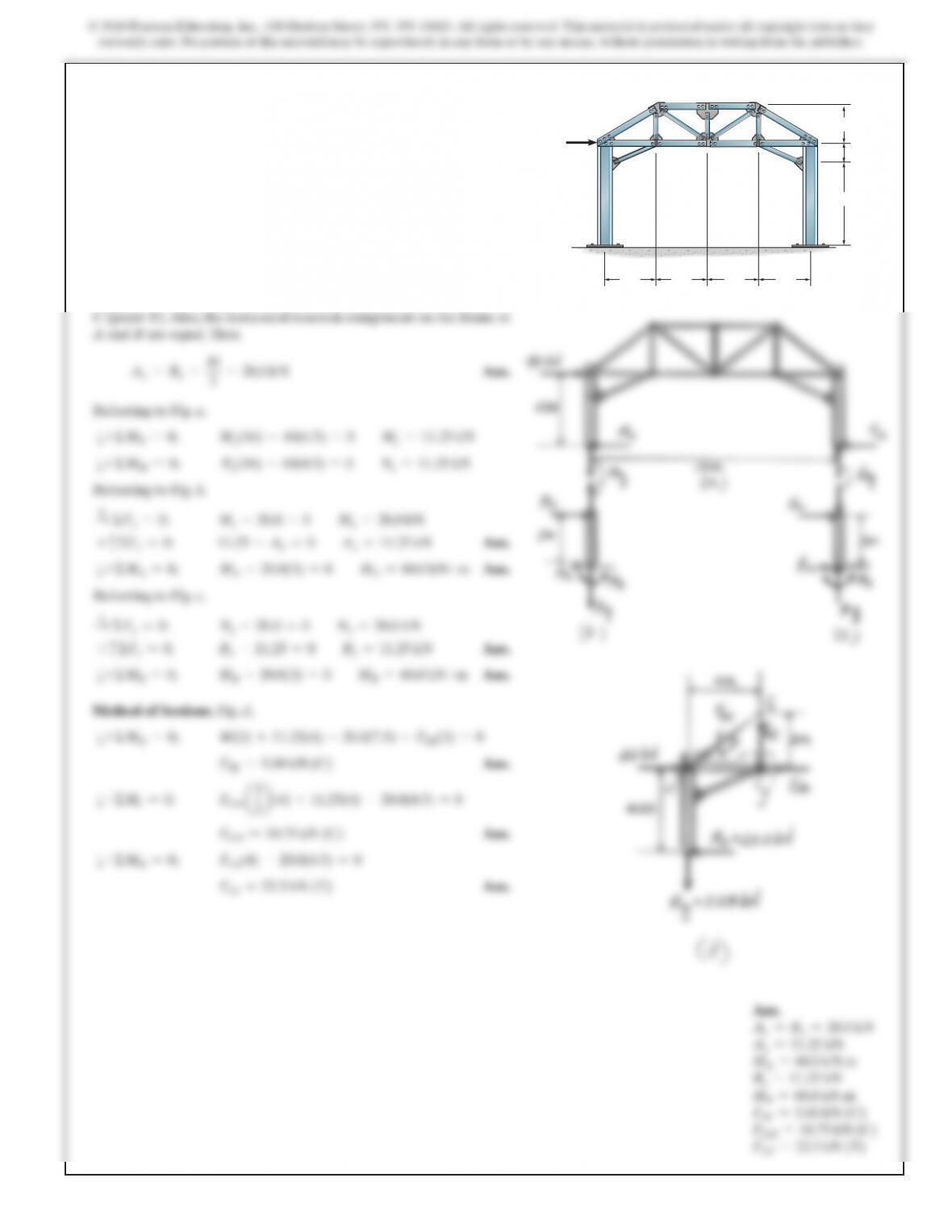
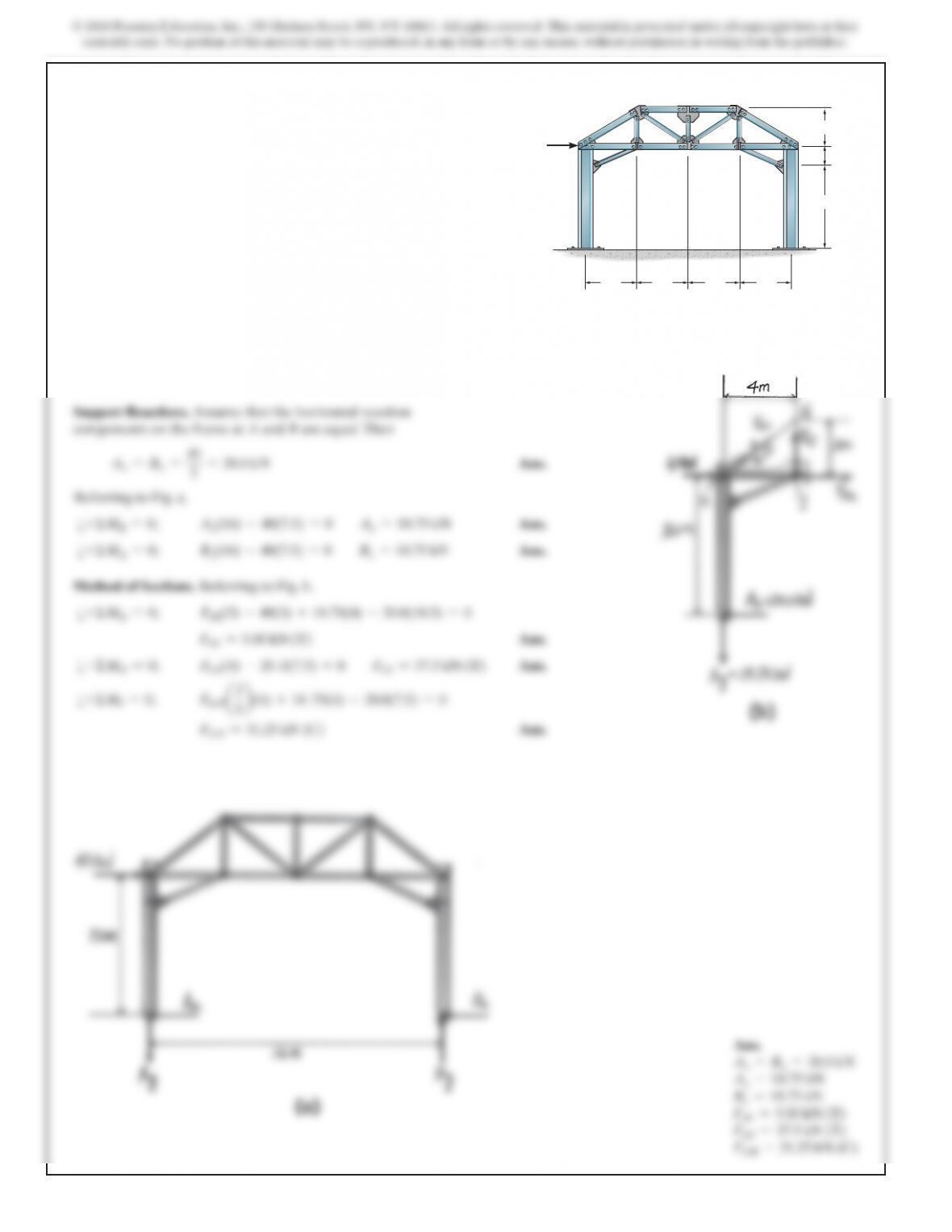
*12–28. Determine (approximately) the force in
members GH, GJ, and JK of the portal frame. Also find the
reactions at the fixed column supports A and B. Assume all
members of the truss to be pin connected at their ends.
D
C
E
H
I
K
F
LJ
G
4 m 4 m 4 m 4 m
6 m
1.5 m
3 m
A
40 kN
B
SOLUTION
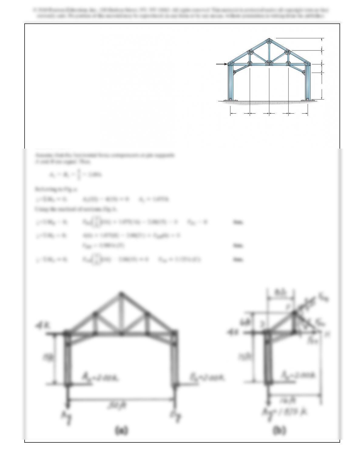
12–29. Solve Prob. 12–28 if the supports at A and B are pin
connected instead of fixed.
D
C
E
H
I
K
F
LJ
G
4 m 4 m 4 m 4 m
6 m
1.5
m
3 m
A
40 kN
B
603
SOLUTION
5b
5b
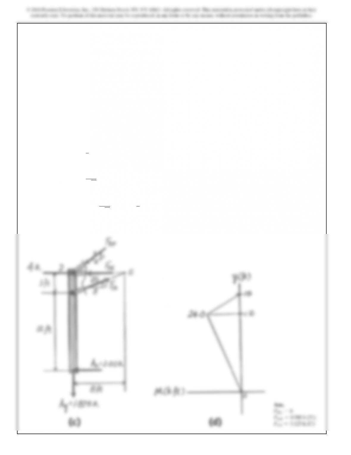
12–30. Draw (approximately) the moment diagram for
column ACD of the portal. Assume all truss members and the
columns to be pin connected at their ends. Also determine the
force in members FG, FH, and EH.D
C
EHI
K
F
L
J
G
8 ft 8 ft 8 ft 8 ft
12 ft
3 ft
6 ft
6 ft
A
4 k
B
12–30. (Continued)
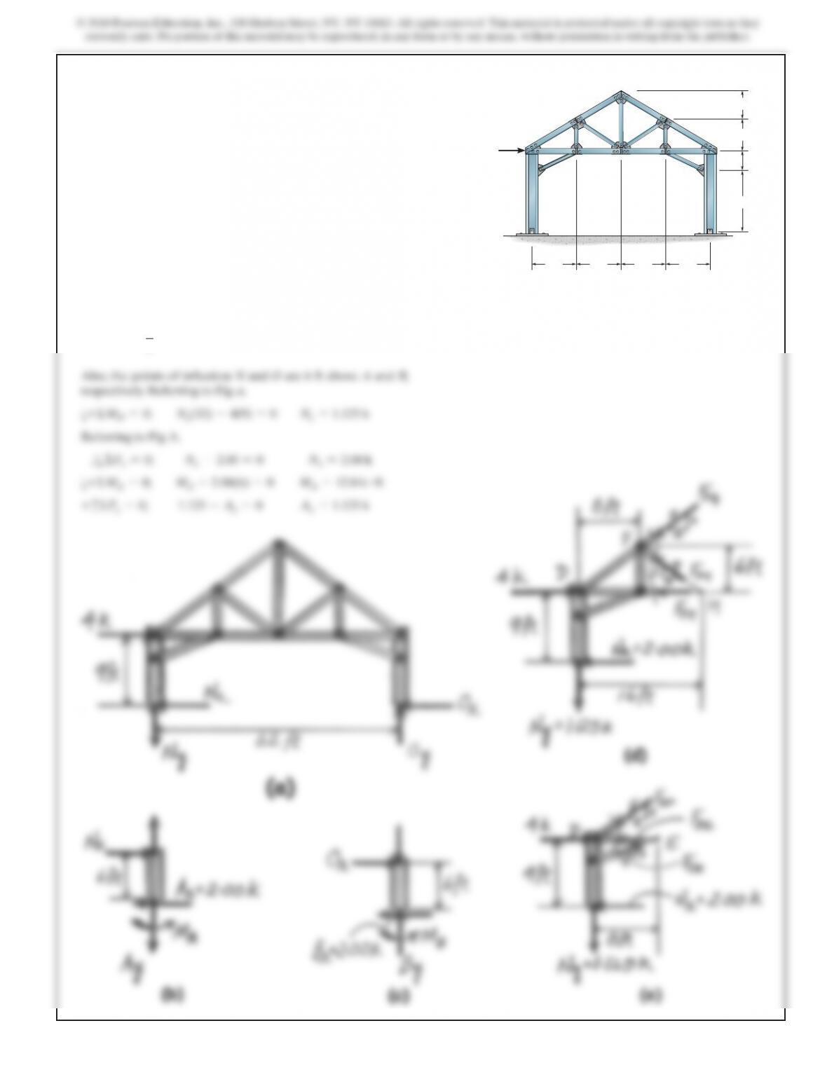
Also, referring to Fig. c,
a
+ΣME=0;
FDF
a3
5b
(8) +1.875(8) –2.00(15) =
0
FDF =3.125
k
(C)
a
+ΣMD=0;
FCE
a3
173 b
(8) –2.00(15) =0
FCE =10.68
k
(T)
+
SΣFx=0;
4+10.68
a8
173 b
–3.125
a4
5b
–2.00 –FDE =
0
FDE =9.50
k
(C)
SOLUTION
Assume that the horizontal force components at fixed supports
A and B are equal. Thus,
A
x=Bx=
4
2
=2.00
k
12–31. Solve Prob. 12–30 if the supports at A and B are fixed
instead of pinned.
D
C
EHI
K
F
L
J
G
8 ft 8 ft 8 ft 8 ft
12 ft
3 ft
6 ft
6 ft
A
4 k
B
606
Ans.
FFG =0;
FEH =0.500
k
(C);
FFH =1.875
k
(C)
173 b
5b
SOLUTION
Assume the horizontal force components at pin supports A and B to be equal. Thus,
A
x=Bx=
2+4
2
=3.00
k
N
*12–32. Draw (approximately) the moment diagram for
column AJI of the portal. Assume all truss members and the
columns to be pin connected at their ends. Also determine the
force in members HG, HL, and KL.
4 kN
2 kN
OK LMN
AB
C
D
E
F
G
J
IH
1.5 m
4 m
1 m
6 @ 1.5 m
5
9 m
SOLUTION
Assume that the horizontal force components at fixed supports
A and B are equal. Therefore,
A
x=Bx=
2+4
2
=3.00
k
N
12–33. Solve Prob. 12–32 if the supports at A and B are fixed
instead of pinned.
4 kN
2 kN
OK LMN
AB
C
D
E
F
G
J
IH
1.5
m
4 m
1 m
6 @ 1.5 m
5
9 m
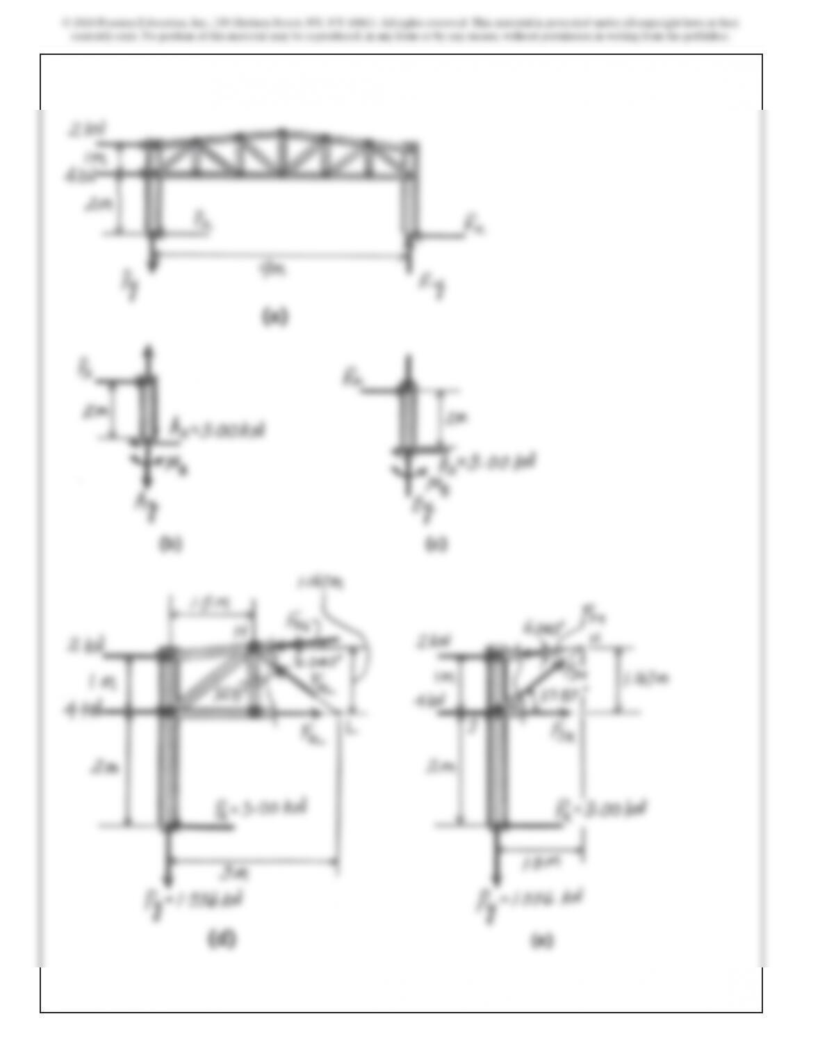
610
12–33. (Continued)
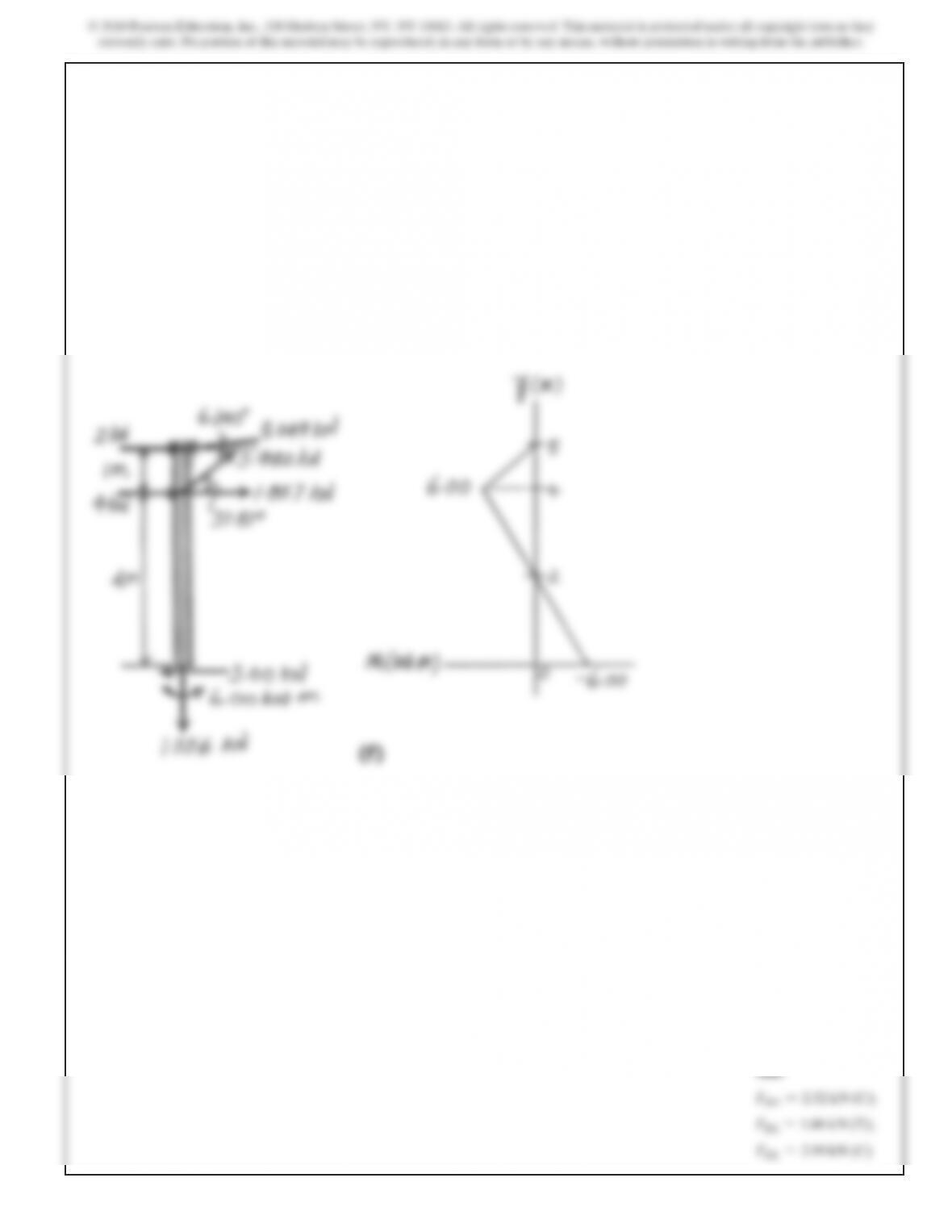
611
12–33. (Continued)
Ans.
FHG =2.52
kN
(C);
FKL =1.86
kN
(T);
FHL =2.99
kN
(C)
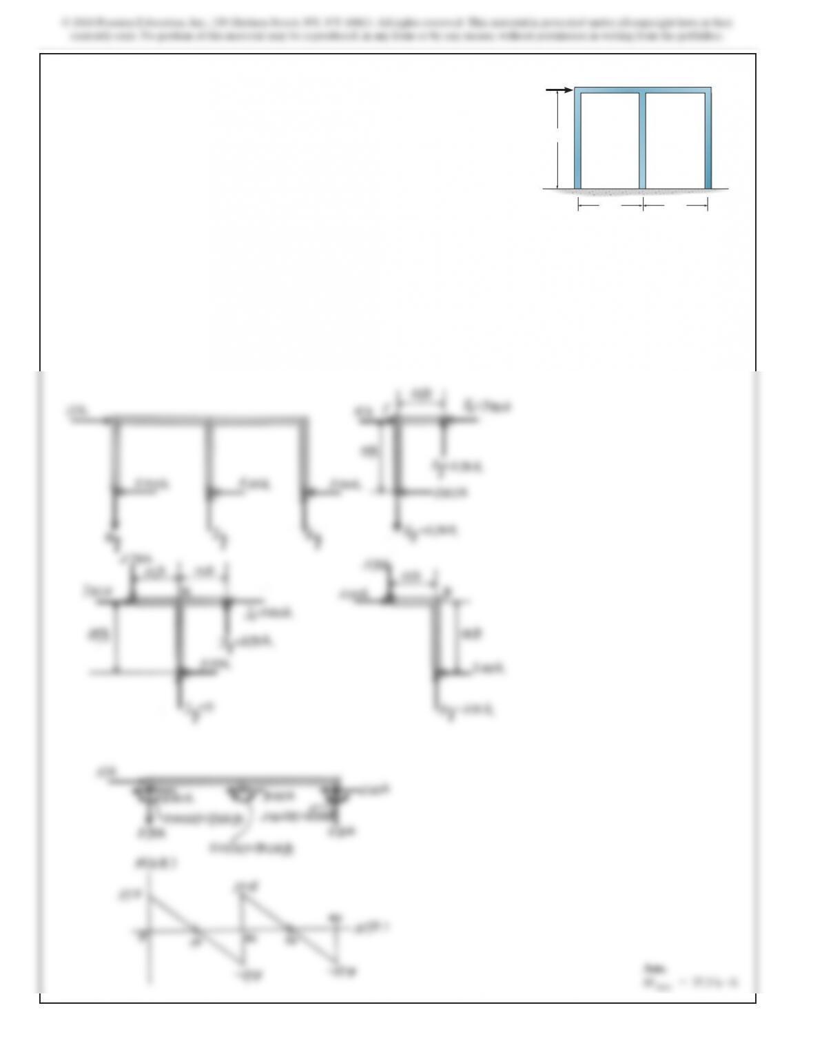
SOLUTION
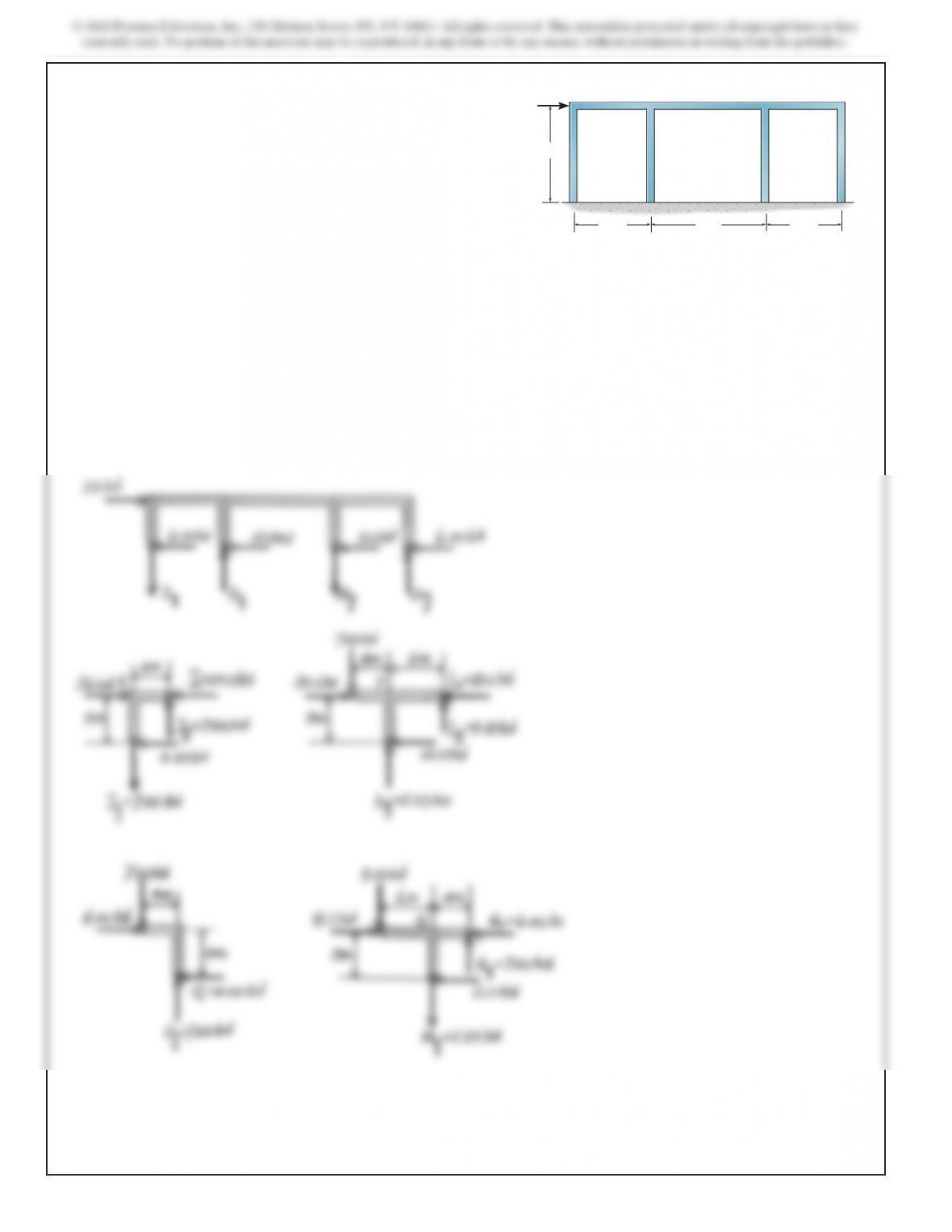
12–34. Use the portal method of analysis and draw the
moment diagram for girder FED.
30 ft
AB C
EDF
20 ft 20 ft
10 k
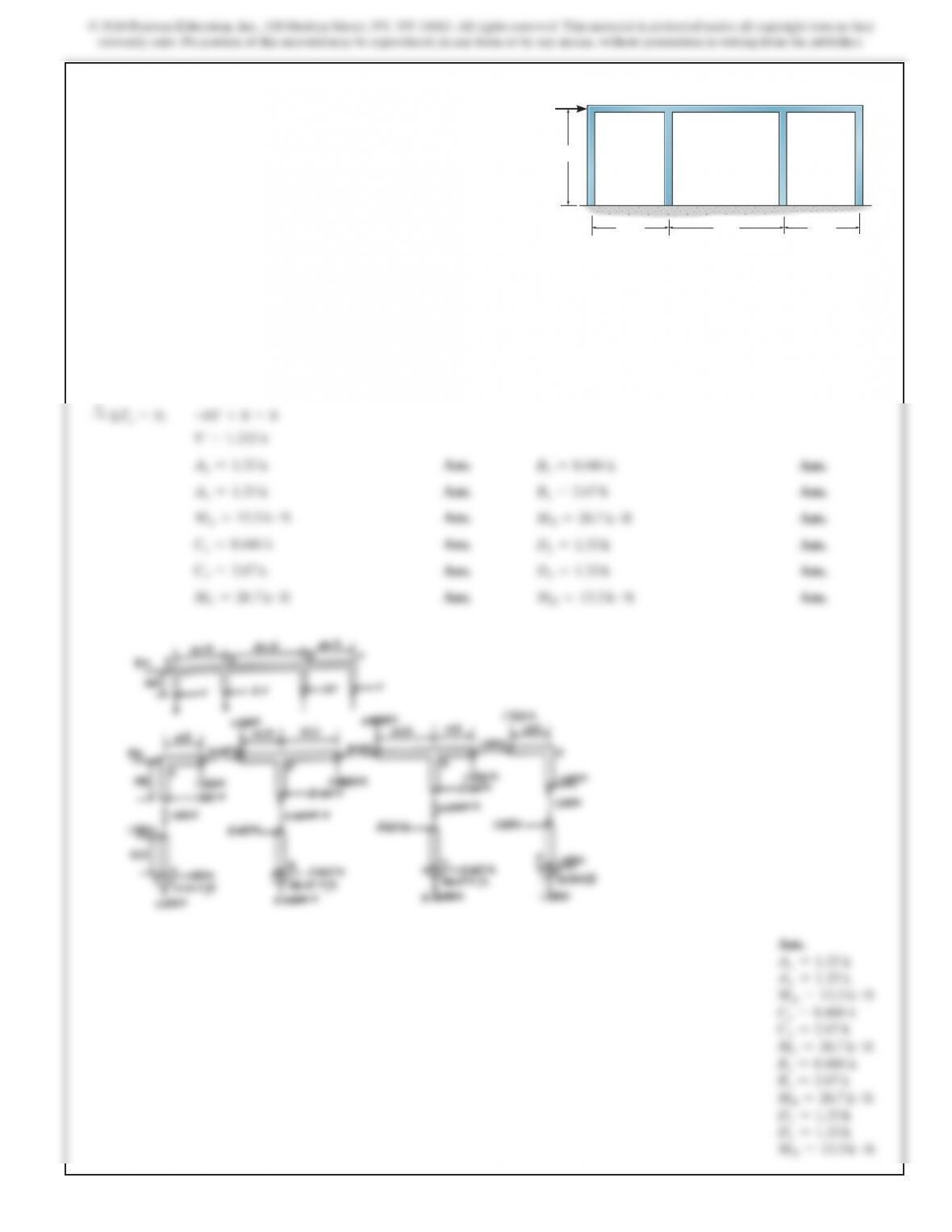
614
SOLUTION
*12–36. Draw (approximately) the moment diagram for the
girder EFGH. Use the portal method.
10 m
AB
CD
EF GH
12 m 8 m
36 kN
8 m