578
SOLUTION
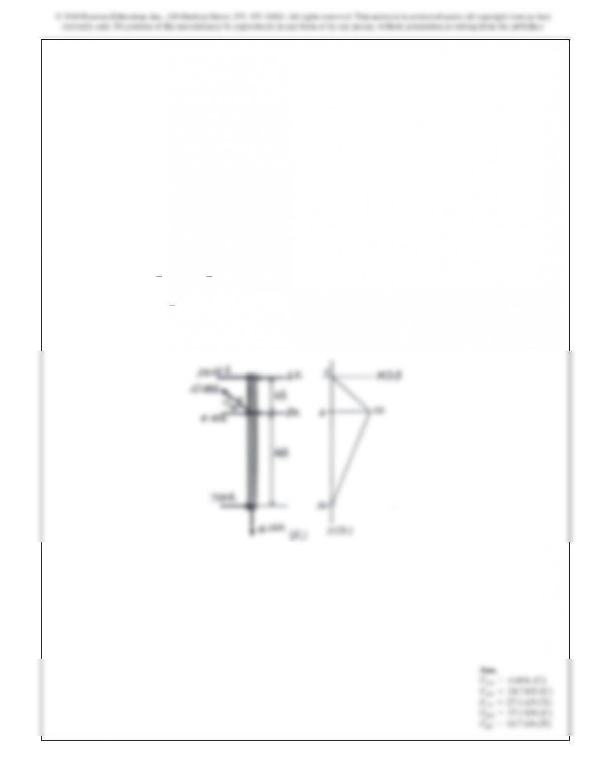
Method of Sections. It is required that
FCE =FDF =F1.
Referring to Fig. a,
+
SΣFx=0;
8–2F1
a3
5b
=0
F1=6.667
k
N
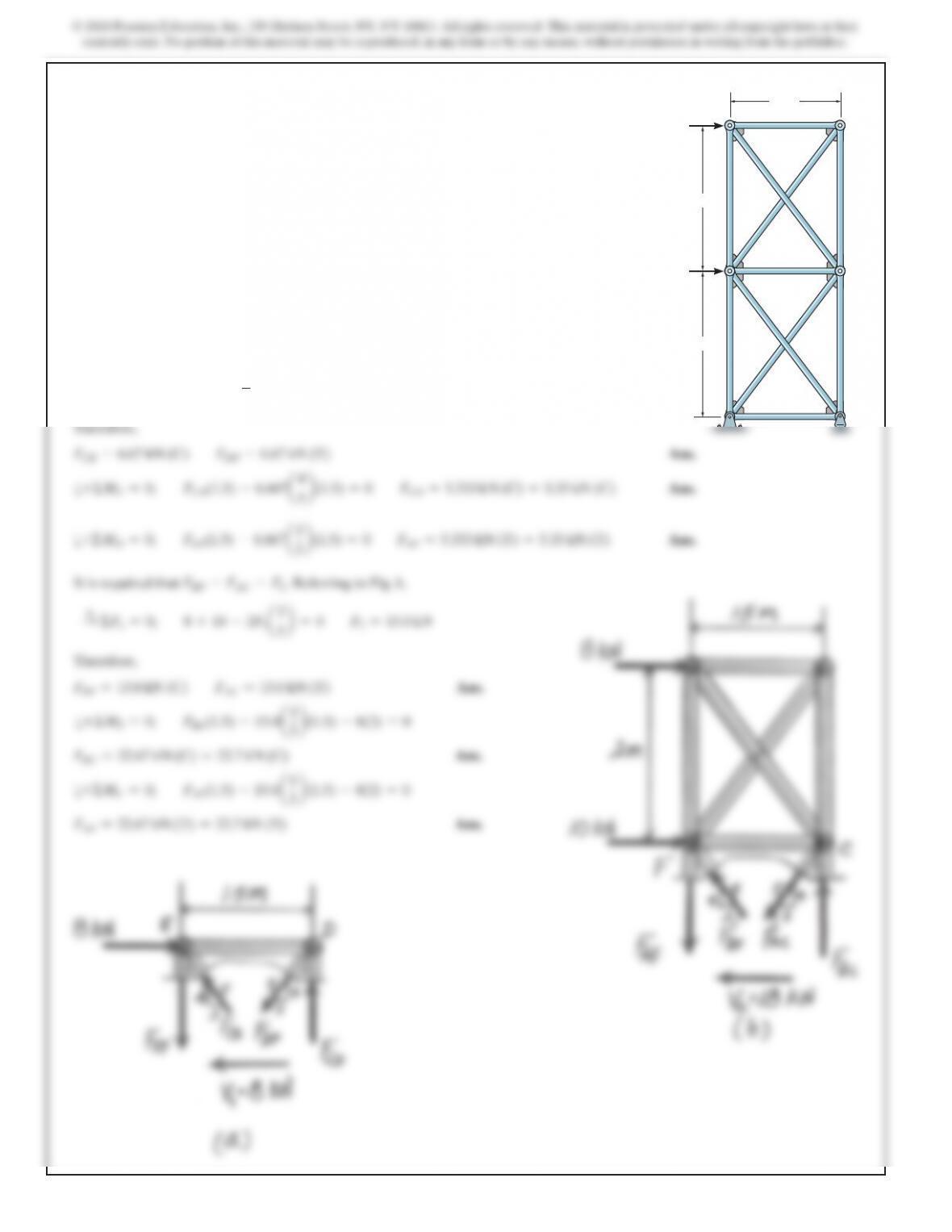
12–11. Determine (approximately) the force in each member of
the truss. Assume the diagonals can support either a tensile or
compressive force. 8 kN
1.5 m
E
F
A
B
C
D
10 kN
2 m
2 m
580
SOLUTION
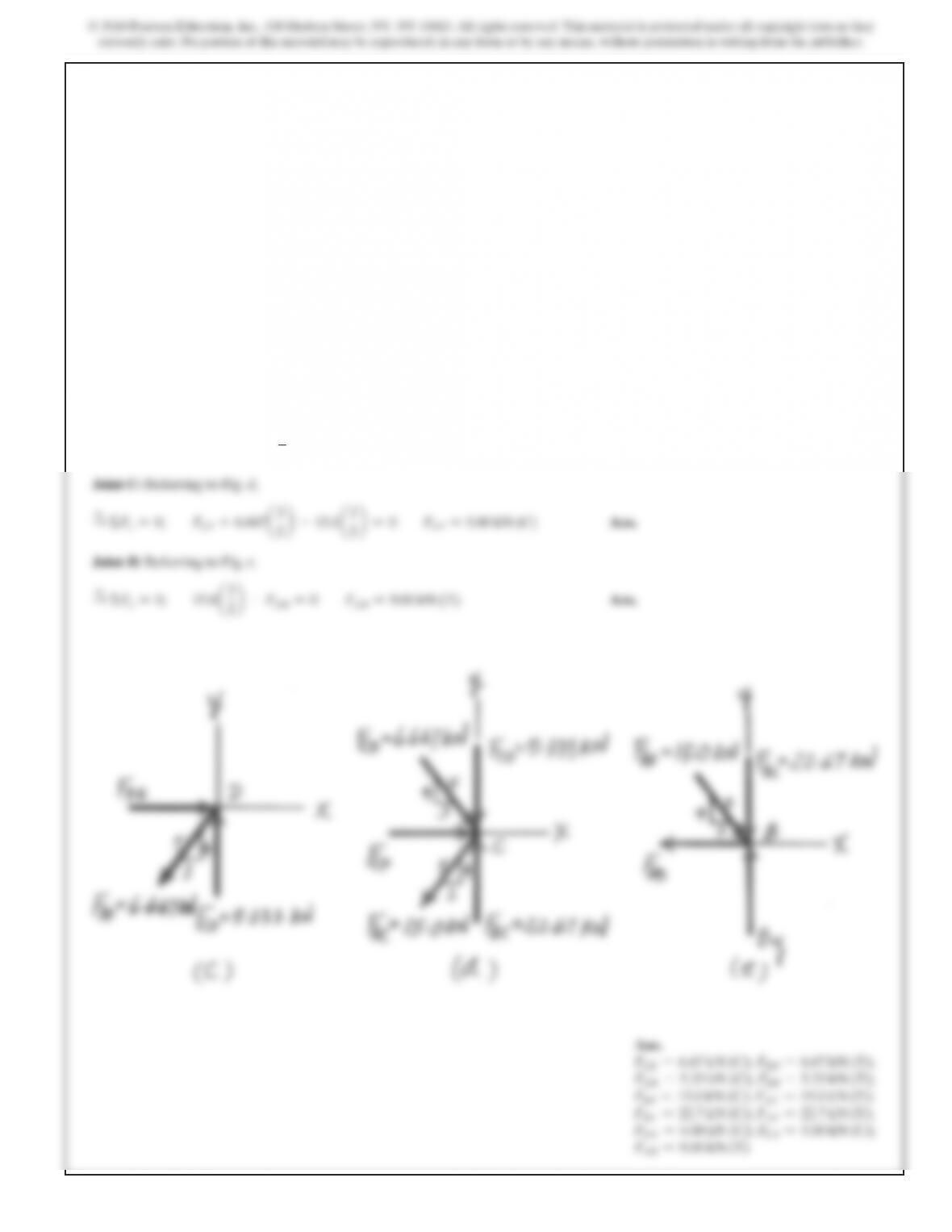
Method of Sections. It is required that
FCE =FBA =0
Ans.
Referring to Fig. a,
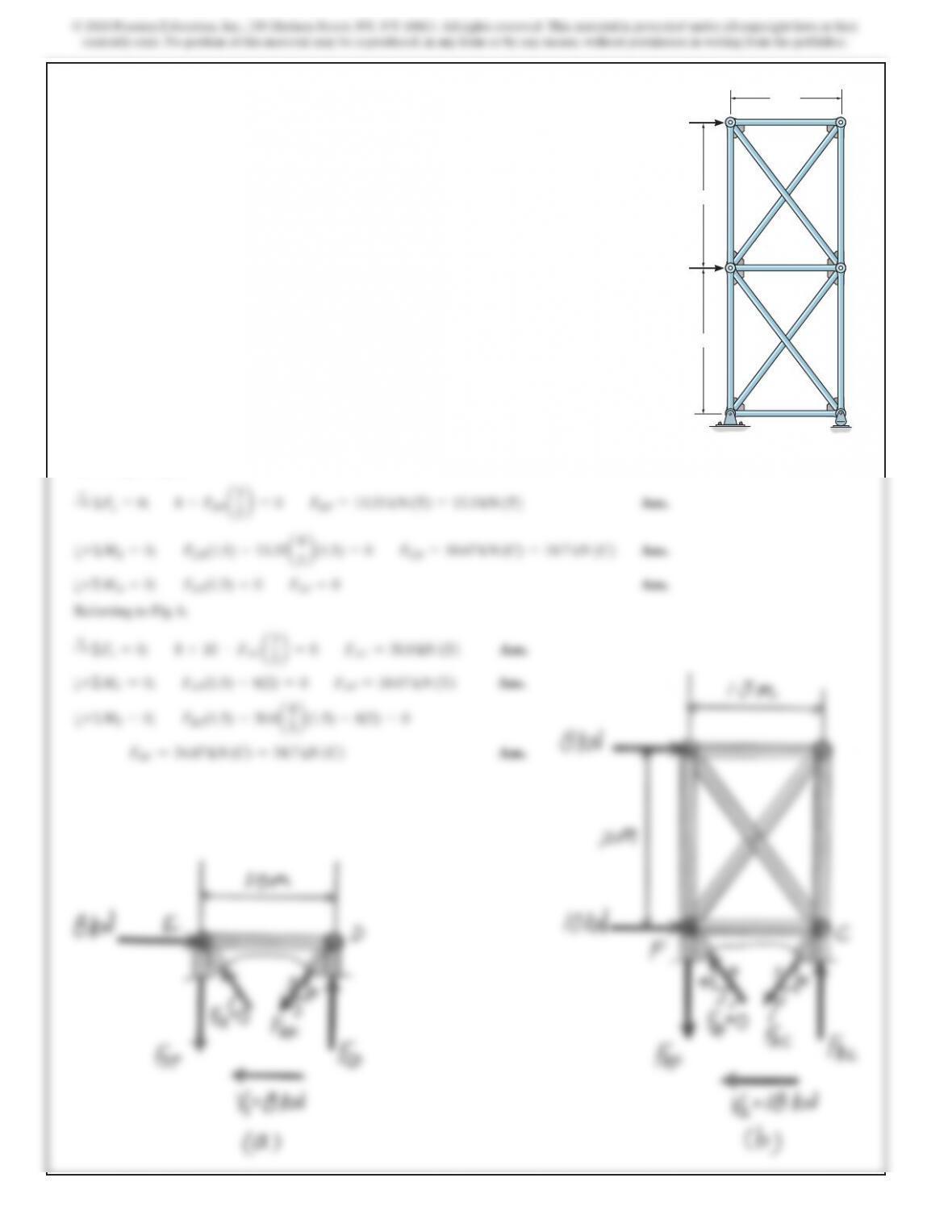
*12–12. Determine (approximately) the force in each member
of the truss. Assume the diagonals cannot support a compressive
force. 8 kN
1.5 m
E
F
A
B
C
D
10 kN
2 m
2 m
SOLUTION
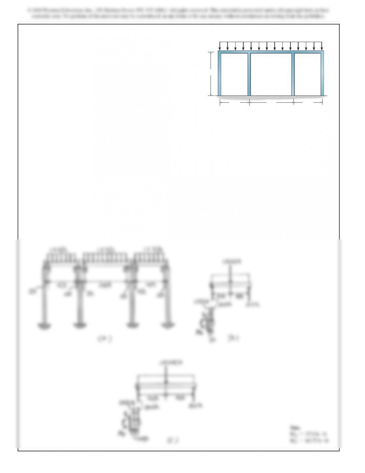
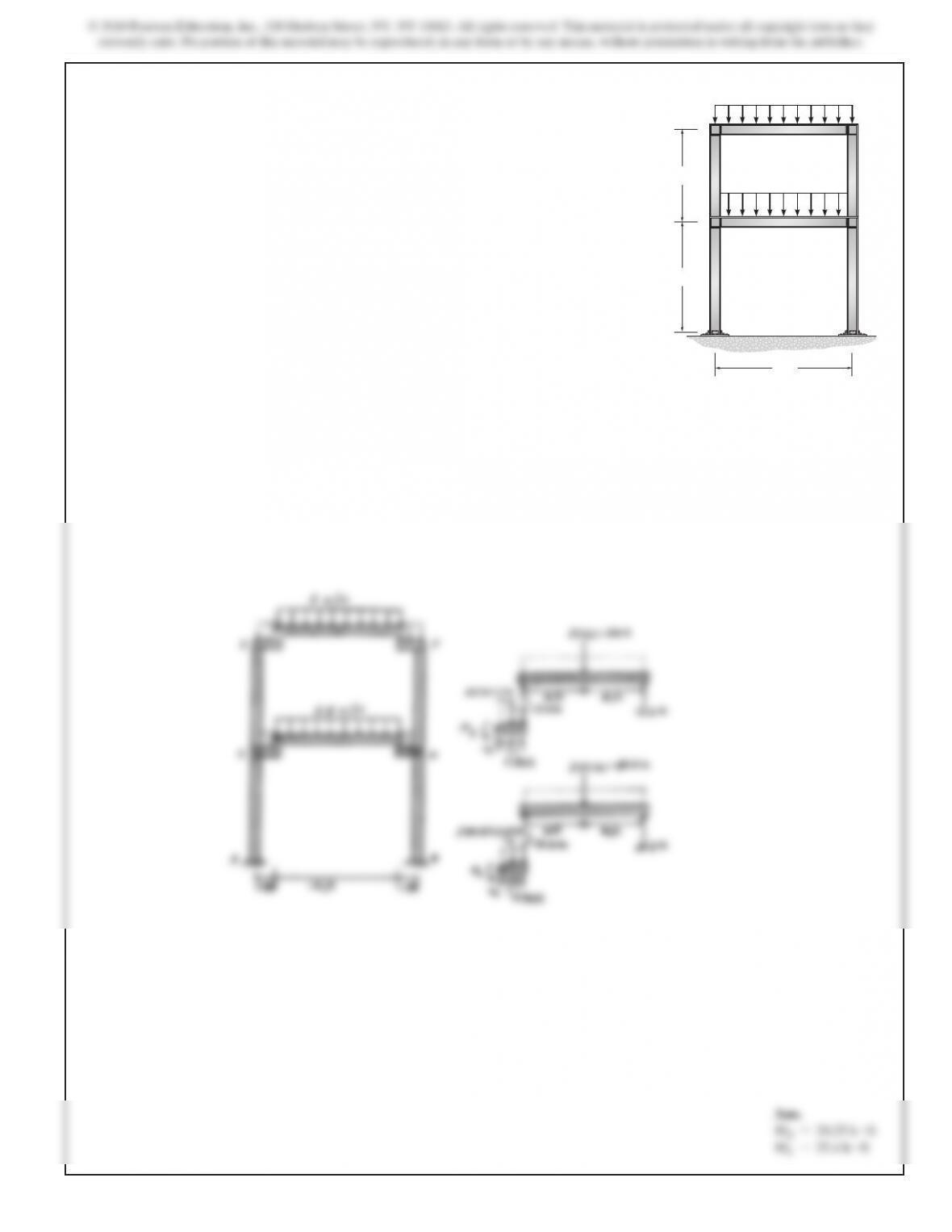
The frame can be simplied to that shown in Fig. a. Referring
to Fig. b,
a+ΣME=0;
ME–1.5(2)(1) –12(2) =0
ME=27.0
k#ft
Ans.
Referring to Fig. c,
a+ΣMF=0;
MF–1.5(3)(1.5) –18.0(3) =0
MF=60.75
k#ft
Ans.
12–13. Determine (approximately) the internal moment that
member EF exerts on joint E and the internal moment that
member FG exerts on joint F.
30 ft
AB
CD
EF
GH
30 ft 20 ft20 ft
1.5 k>ft
584
SOLUTION
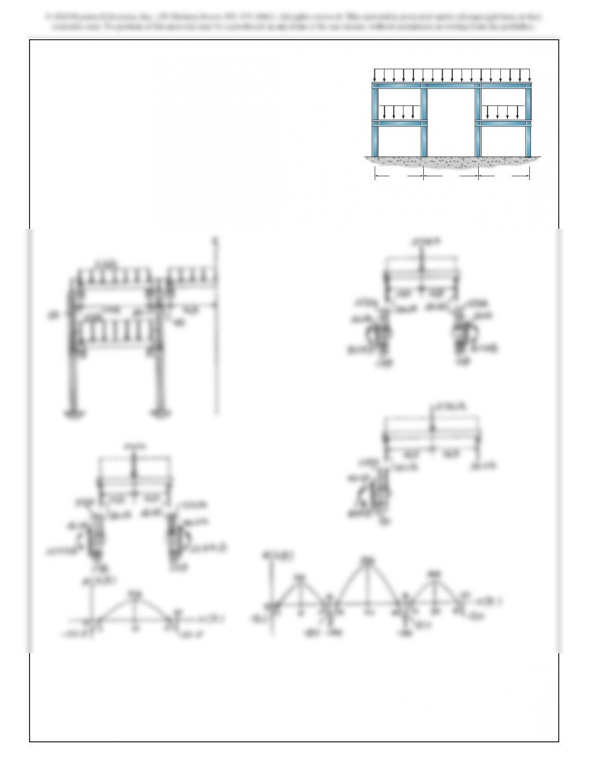
12–15. Draw the approximate moment diagrams for each of
the five girders.
A
BD
E
F
KL
G
HIJ
C
3 k>ft 3 k>ft
2 k>ft
30 ft 40 ft 30 ft
585
ME=20.25
k#ft
MC=35.4
k#ft
ME=20.25
k#ft
SOLUTION
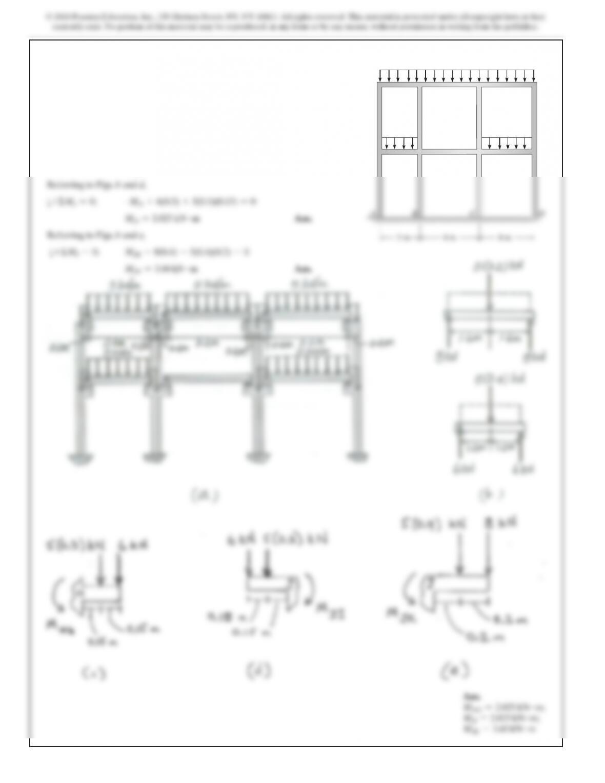
The frame can be simplied to that shown in Fig. a. Referring
to Figs. b and c,
a+ΣMH=0;
MHG –6
(0.3) –5(0.3)(0.15) =0
MHG =2.025
kN #m
Ans.
a+ΣMJ=0;
–MJI +6(0.3) +5(0.3)(0.15) =0
MJI =2.025
kN #m
Ans.
Referring to Figs. b and e,
a+ΣMJ=0;
MJK –8(0.4) –5(0.4)(0.2) =0
MJK =3.60
kN #m
Ans.
Ans.
MHG =2.025
kN #m;
MJI =2.025
kN #m;
MJK =3.60
kN #m
12–17. Determine (approximately) the internal moments at
joint H from HG and at joint J from JI and JK.
H
I
GF
K
L
E
J
5 kN>m
5 kN>m5 kN>m
4 m4 m3 m
© 2018 Pearson Education, Inc., 330 Hudson Street, NY, NY 10013. All rights reserved. This material is protected under all copyright laws as they
currently exist. No portion of this material may be reproduced, in any form or by any means, without permission in writing from the publisher.
SOLUTION
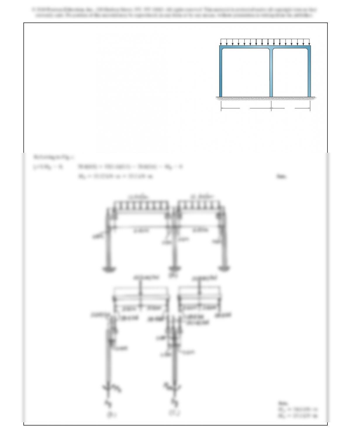
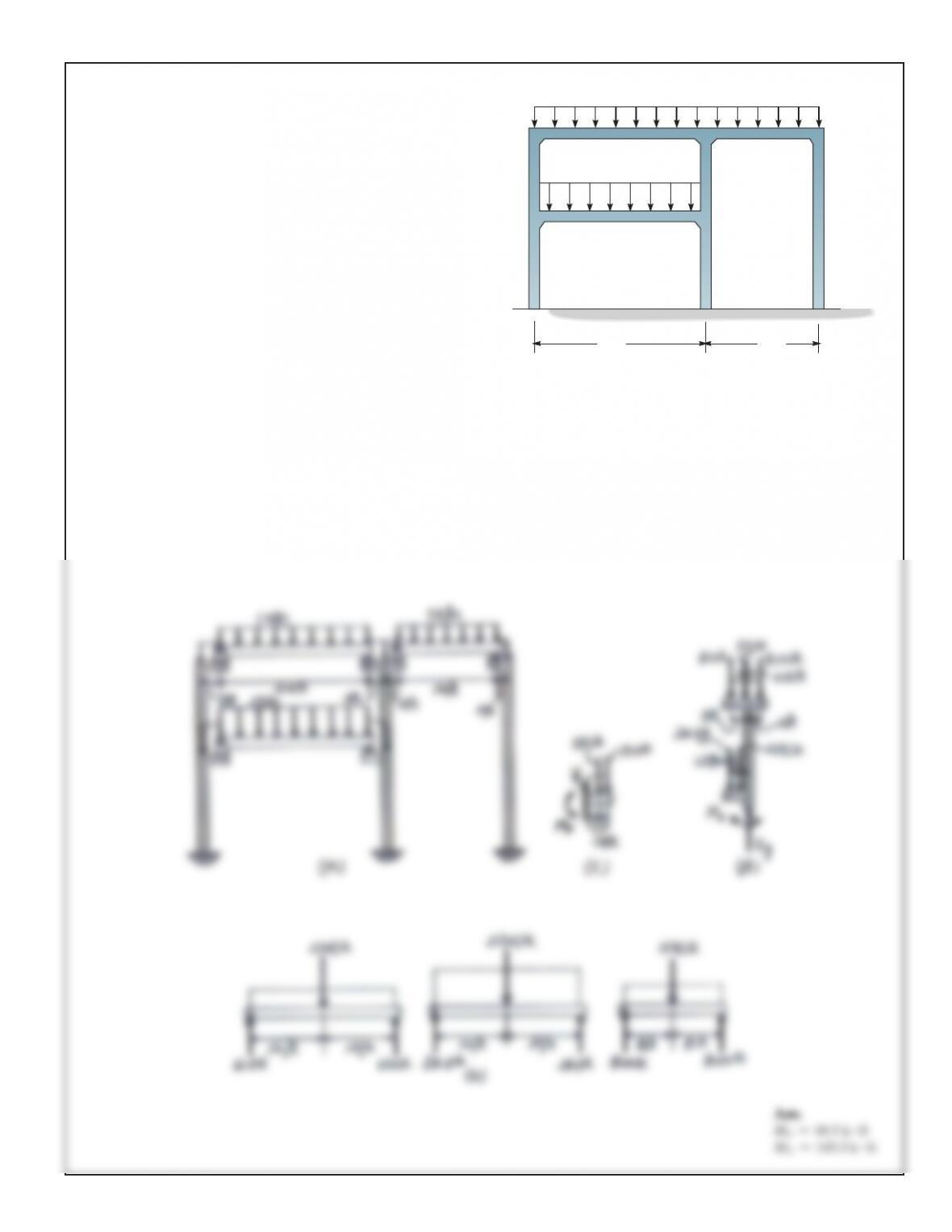
The frame can be simplied to that shown in Fig. a. The vertical
reactions on the beams are shown in Fig. b. Referring to Fig. c,
a+ΣMF=0;
MF–1(3)(1.5) –12.0(3) =0
MF=40.5
k#ft
Ans.
Referring to Fig. d,
a+ΣME=0;
12.0(3) +1(5)(0.5) +24.0(3) +2(3)(1.5) –8.00(2) –ME=0
ME=103.5
k#ft
Ans.
12–18. Determine (approximately) the internal moments at
joint F from FG and at joint E on the column.
20 ft30 ft
A
D
F
C
H
G
E
B
1 k>ft
2 k>ft
SOLUTION
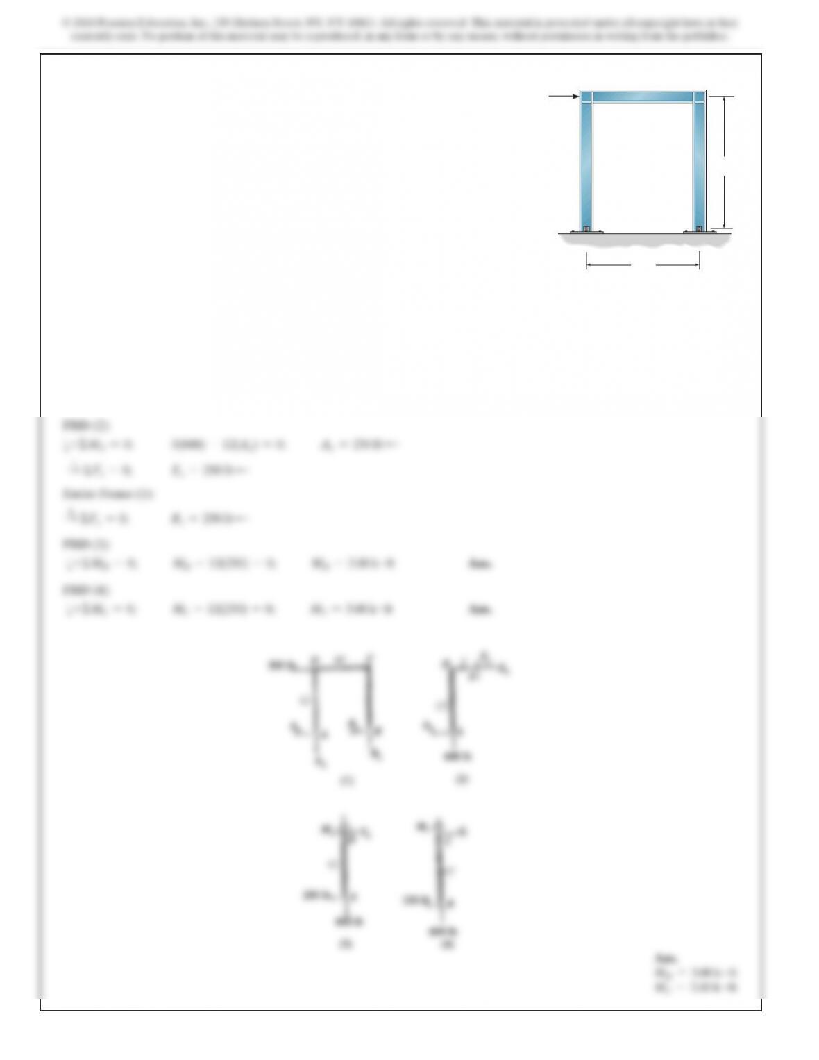
Entire Frame (1):
a+ΣMA=0;
10By–12(500) =0;
By=600
lb
c
+
c
ΣFy=0;
Ay=600
lbT
12–19. Determine (approximately) the internal moments at
joints D and C. Assume the supports at A and B are pins.
12 ft
500 lb
10 ft
A
D
B
C
589
MA=45.0
k#ftB
MB=45.0
k#ft
VA=5.00
k
VB=–7.5
k
MA=30.0
k#ftB
MB=60.0
k#ft
VA=5.00
k
VB=–10.0
k
k
VB=–15.0
k
590
SOLUTION
Support Reactions.
Assume that the horizontal reaction components on the frame at A and B are equal. Then
A
x=Bx=
10 +18
2
=14.0
k
N
Referring to Fig. a,
a+ΣMB=0;
Ay(6) –10(6) –18(4) =0
Ay=22.0
kN
113 b
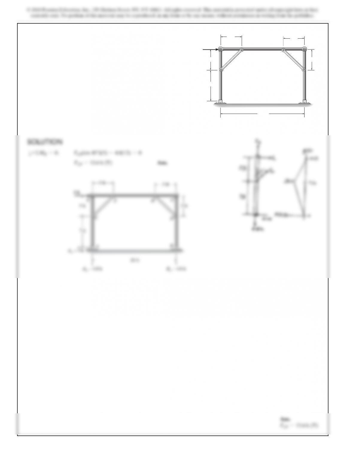
12–21. Determine (approximately) the force in each truss
member of the portal frame. Assume all members of the truss
to be pin connected at their ends. 1 m
18 kN
10 kN
B
A
E
H
GF
D
I
C
4 m
2 m
3 m 3 m
1
m
592
SOLUTION
Support Reactions. Assume that zero moment occurs at the
mid-height of the column between A and C (point J) and
between B and D (point K). Also, the horizontal reaction
components at J and K are equal. Then
J
x=Kx=
10 +18
2
=14.0
k
N
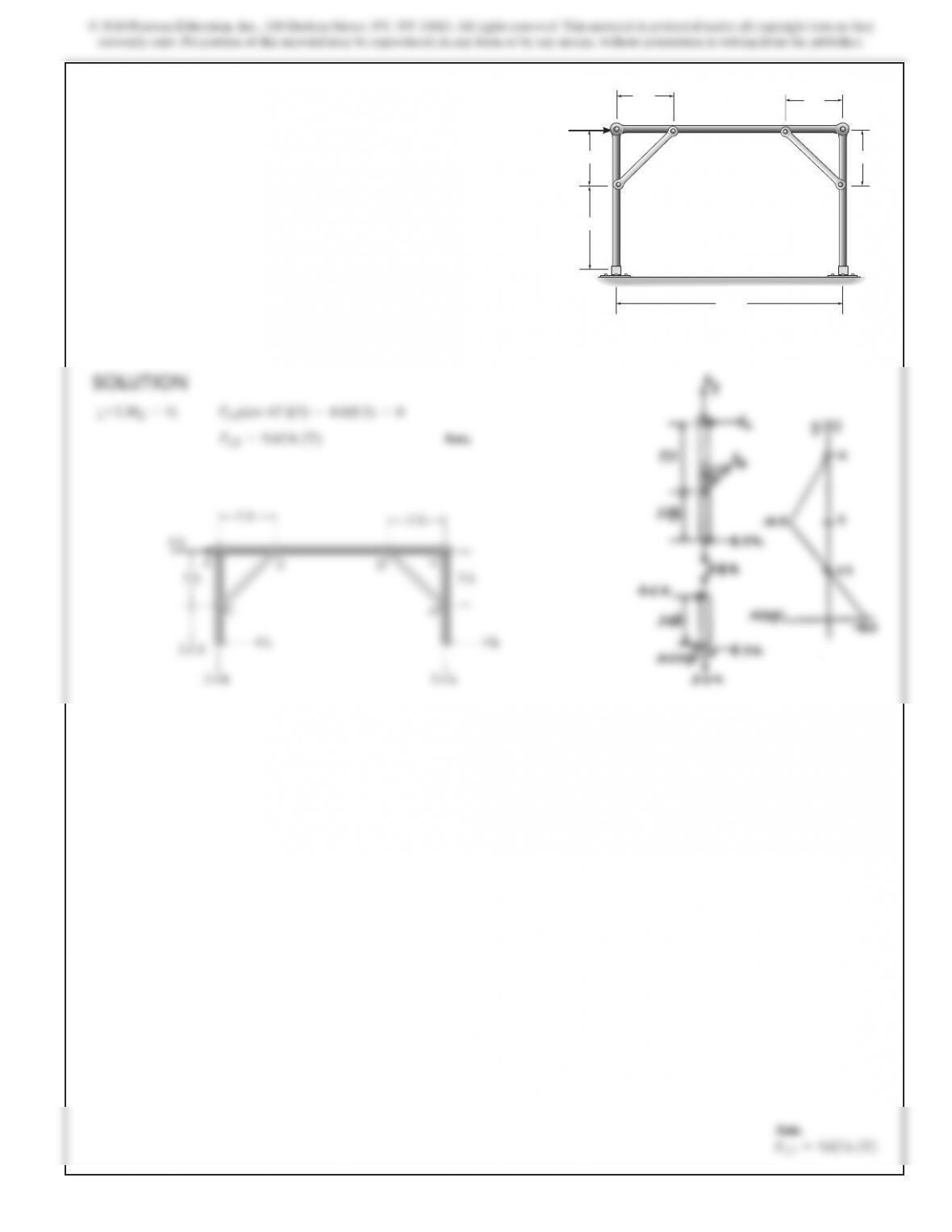
12–22. Solve Prob. 12–21 if the supports at A and B are fixed
instead of pinned.
1
m
18 kN
10 kN
B
A
E
H
GF
D
I
C
4 m
2 m
3 m 3 m
1
m
595
Ans.
FCF =9.62
k
(T)
8
k
5 ft
3.4 k
4
k
3.5 ft
5 ft
5 ft
5 ft
C
F
EG
H
D
3.4 k
4 k
596
SOLUTION
Support Reactions. Assume that the horizontal reaction components
on the frame at A and B are equal. Then
A
x=Bx=
6+8
2
=7.00
k
5b
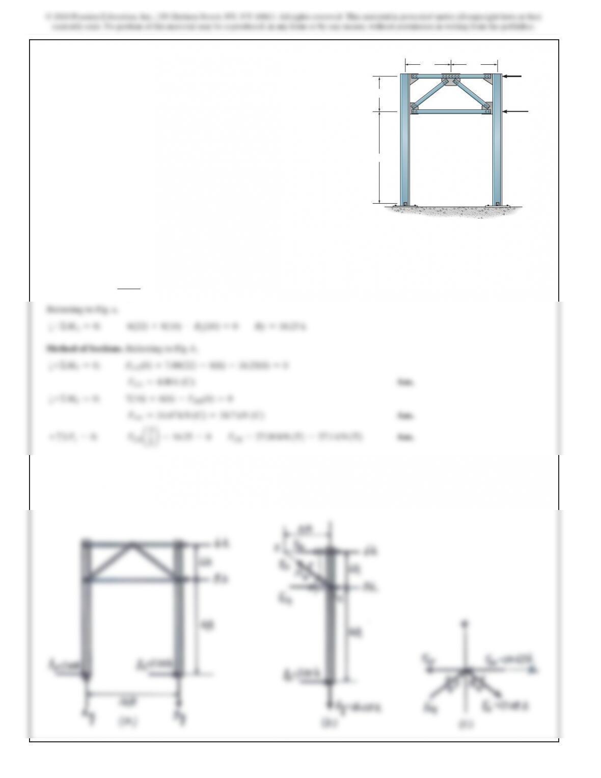
12–25. Draw (approximately) the moment diagram for
column BCD of the portal. Assume all truss members and the
columns to be pin connected at their ends. Also determine the
force in all the truss members.
8 ft 8 ft
6 ft
16 ft
AB
D
G
F
C
E
6 k
8
k