538
SOLUTION
FEMAC =0
FEMBD =0
F
EMCD =–wL
2
12
=–
6(82)
12
=–32 kN #m=–FEMD
C
F
EMDE =–wL
2
8
=–
6(72)
8
=–36.75 kN #
m
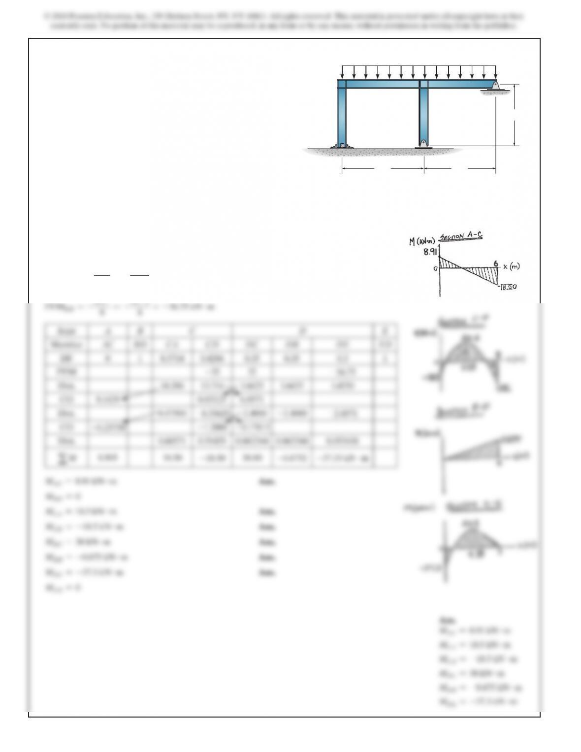
Joint A B C D E
Member AC BD CA CD DC DB DE ED
DF 0 1 0.5714 0.4286 0.35 0.35 0.3 1
FEM
–32
32
–36.75
Dist. 18.286 13.714 1.6625 1.6625 1.4250
CO 9.1429 0.83125 6.8571
Dist. 0.47500
–0.35625
–2.4000
–2.4000
–2.0571
CO
–0.23750
–1.2000
–0.17813
Dist. 0.68571 0.51429 0.062344 0.062344 0.053438
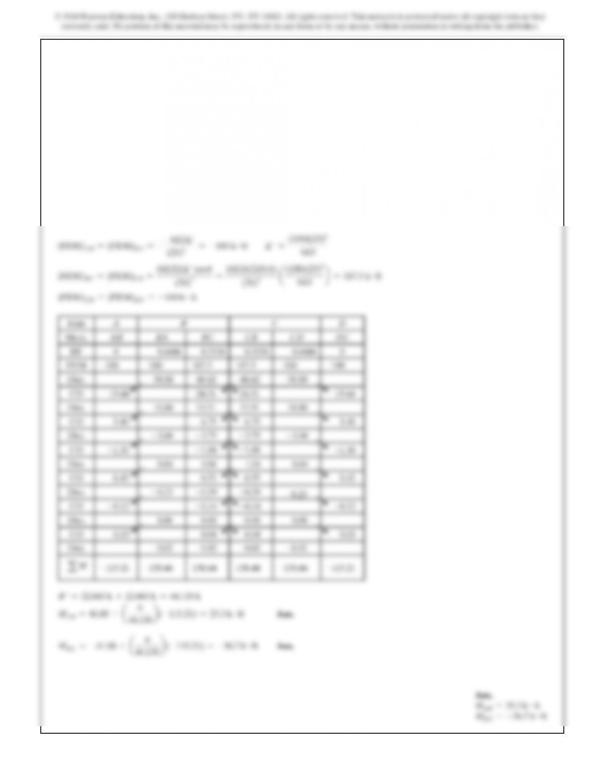
aM
8.905 18.50
–18.50
38.00
–0.6752
–37.33
kN #m
MAC =8.91 kN #m
Ans.
MBD =0
MCA =18.5 kN #m
Ans.
MCD =–18.5 kN #m
Ans.
MDC =38 kN #m
Ans.
MDB =–0.675 kN #m
Ans.
MDE =–37.3 kN #m
Ans.
MED =0
Ans.
MAC =8.91 kN #m
MCA =18.5 kN #m
MCD =–18.5 kN #m
MDC =38 kN #m
MDB =–0.675 kN #m
MDE =–37.3 kN #m
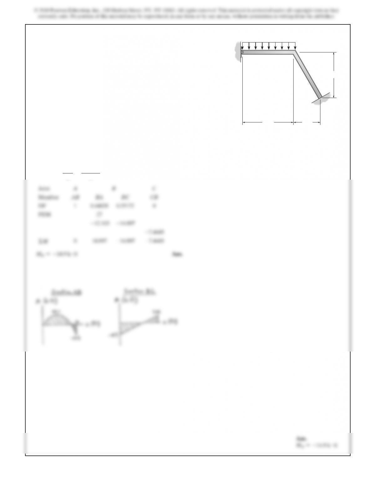
11–18. Determine the moments at A, C, and D, then
draw the moment diagram for each member of the frame.
Support A and joints C and D are fixed connected. EI is
constant.
6 kN>m
A
D
B
C
8 m
6 m
7 m
E
540
SOLUTION
Member Stiffness Factor and Distribution Factor.
K
AB =
4EI
LAB
=
4EI
12
=
EI
3
KBC =KBE =KCD =
4EI
L
=
4EI
16
=
EI
4
(
DF)AB =(DF)EB =(DF)DC =0
(DF)BA =
EI>3
EI>3+EI>4+EI>4
=0.
4
(
DF)BC =(DF)BE =
EI>4
EI>3+EI>4+EI>4
=0.
3
(
DF)CB =(DF)CD =
EI>4
EI>4+EI>4
=0.
5
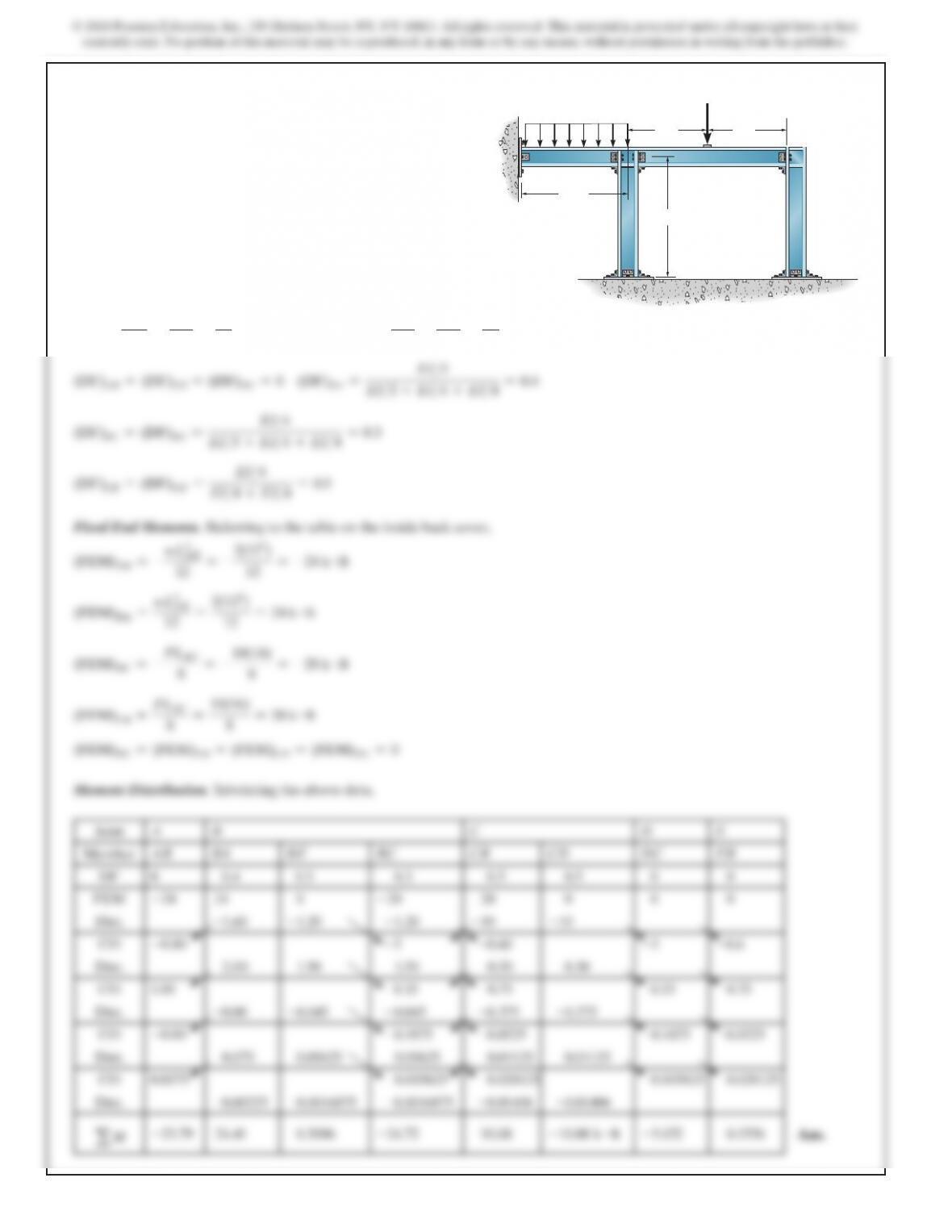
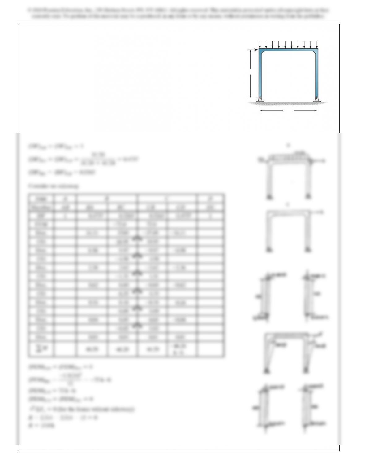
Fixed End Moments. Referring to the table on the inside back cover,
(
FEM)AB =–
wL
AB
2
12
=–
2(122)
12
=–24 k #f
t
(
FEM)BA =
wL
AB
2
12
=
2(122)
12
=24 k #ft
(
FEM)BC =–
PL
BC
8
=–
10(16)
8
=–20 k
#
f
t
(
FEM)CB =
PL
BC
8
=
10(16)
8
=20 k
#
f
t
(FEM)BE =(FEM)EB =(FEM)CD =(FEM)DC =0
*11–20. Determine the moments at B and C, then draw the
moment diagram for each member of the frame. Assume the
supports at A, E, and D are fixed. EI is constant.
B
E
C
A
10 k
2 k>ft
8 ft 8 ft
12 ft
16 ft
D
a
541
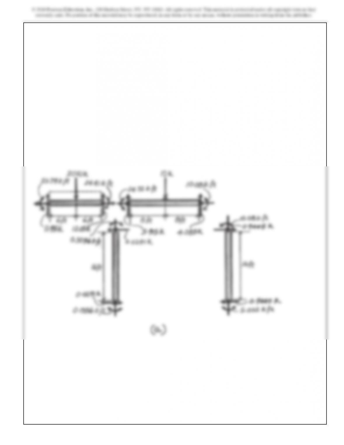
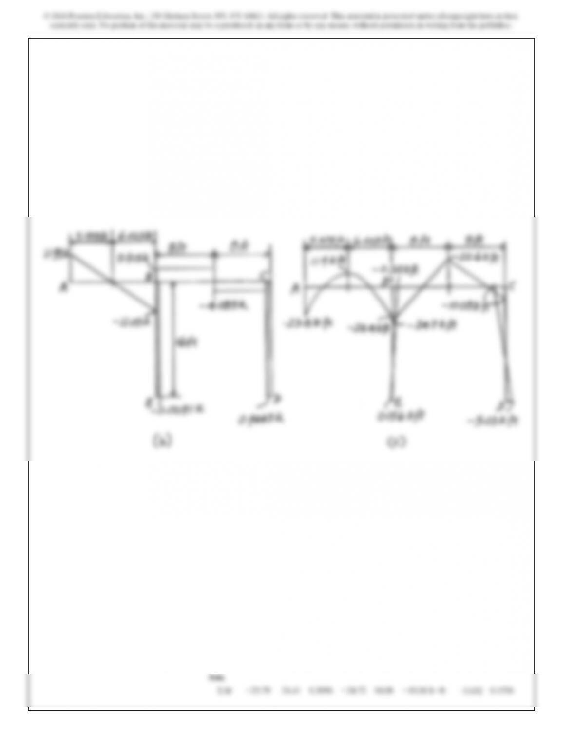
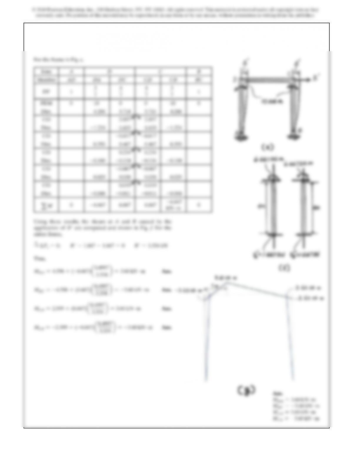
Using these results, the shear at both ends of members AB, BC,
BE, and CD are computed and shown in Fig. a. Subsequently,
the shear and moment diagrams can be plotted.
*11–20. (Continued)
542
543
SOLUTION
K
DA =KCB =
3EI
L
=
3EI
4
KCD =
4EI
L
=
4EI
4
=EI
(
DF)AD =(DF)BC =1
(DF)DA =(DF)CB =
3EI>4
3EI>4+EI
=
3
7
(
DF)DC =(DF)CD =
EI
3EI>4+EI
=
4
7
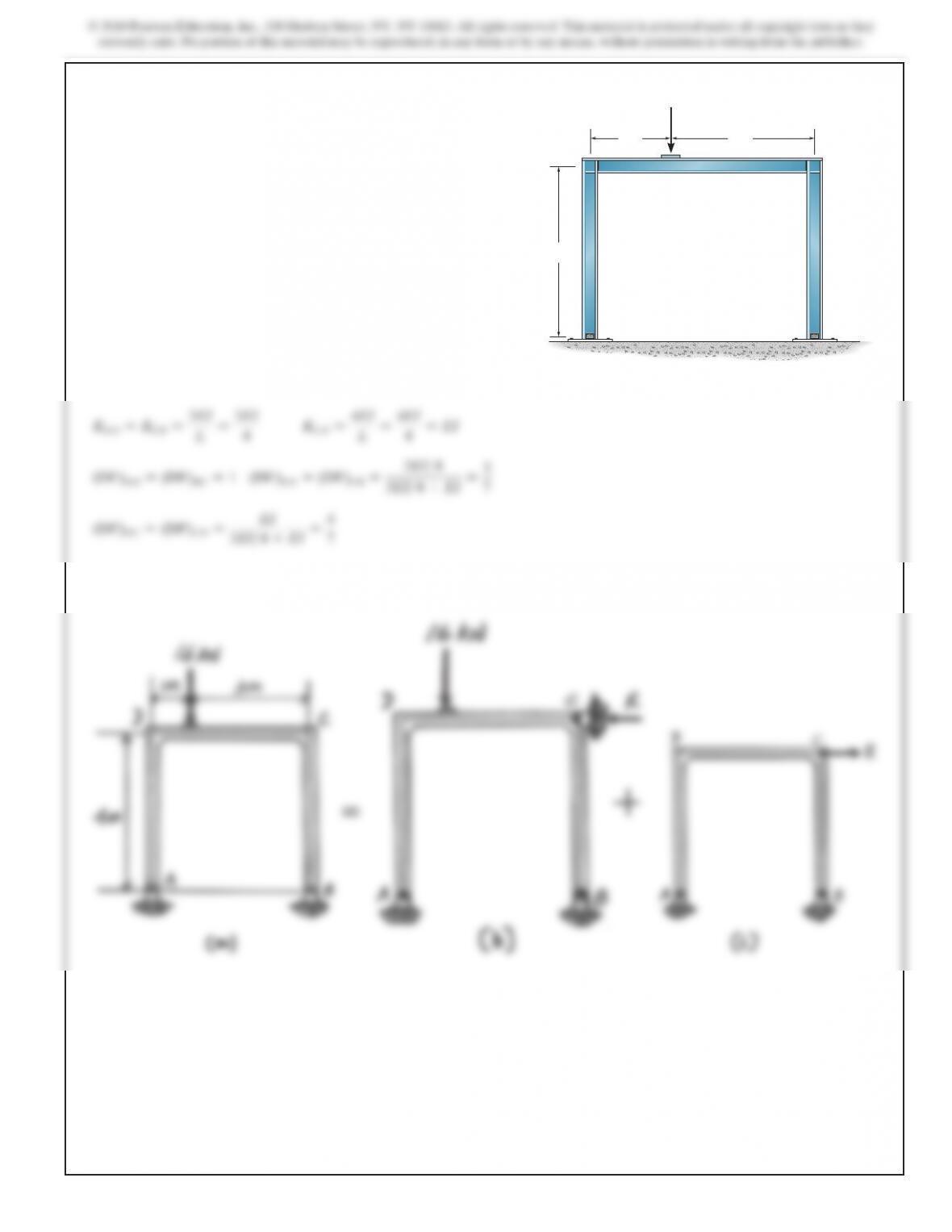
11–21. Determine the moments at D and C, then draw the
moment diagram for each member of the frame. Assume the
supports at A and B are pins. EI is constant.
B
C
D
A
4 m
1 m3 m
16 kN
547
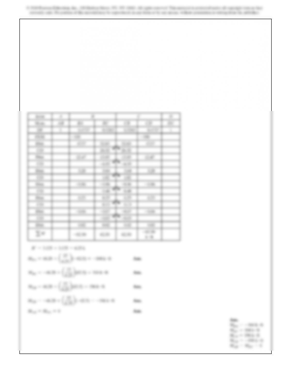
Ans.
MBA =–104 k #ft
MBC =104 k #ft
MCB =196 k #ft
MCD =–196 k #ft
MAB =MDC =0
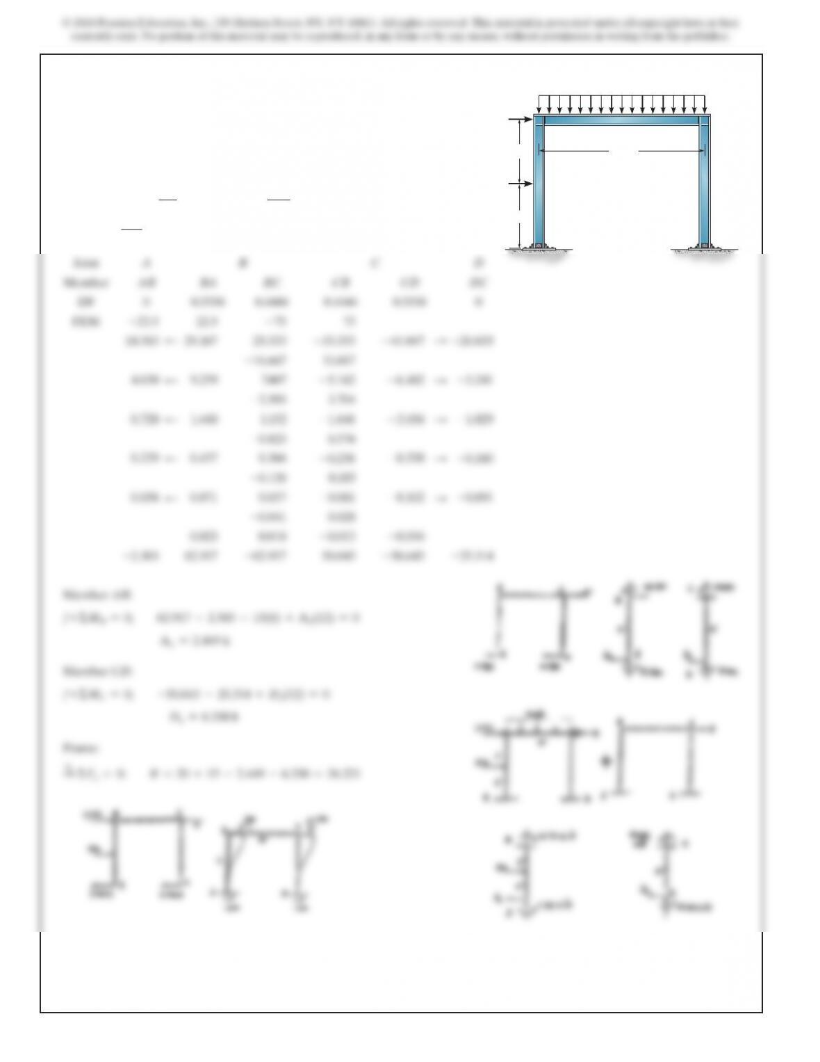
11–23. Determine the moments at the ends of each member
of the frame. The members are fixed connected at the supports
and joints. EI is the same for each member. BC
DA
6 ft
6 ft 15 ft
20
k
15
k
4 k>ft
SOLUTION
FEMs for AB use
PL
8
,
and for BA use
wL2
12
.
Each member
has a
K
=
4EI
L
.
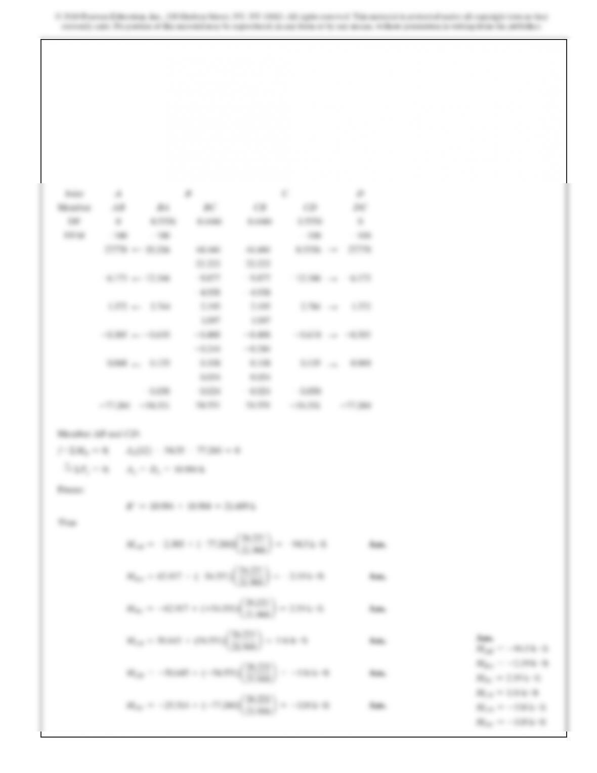
11–23. (Continued)
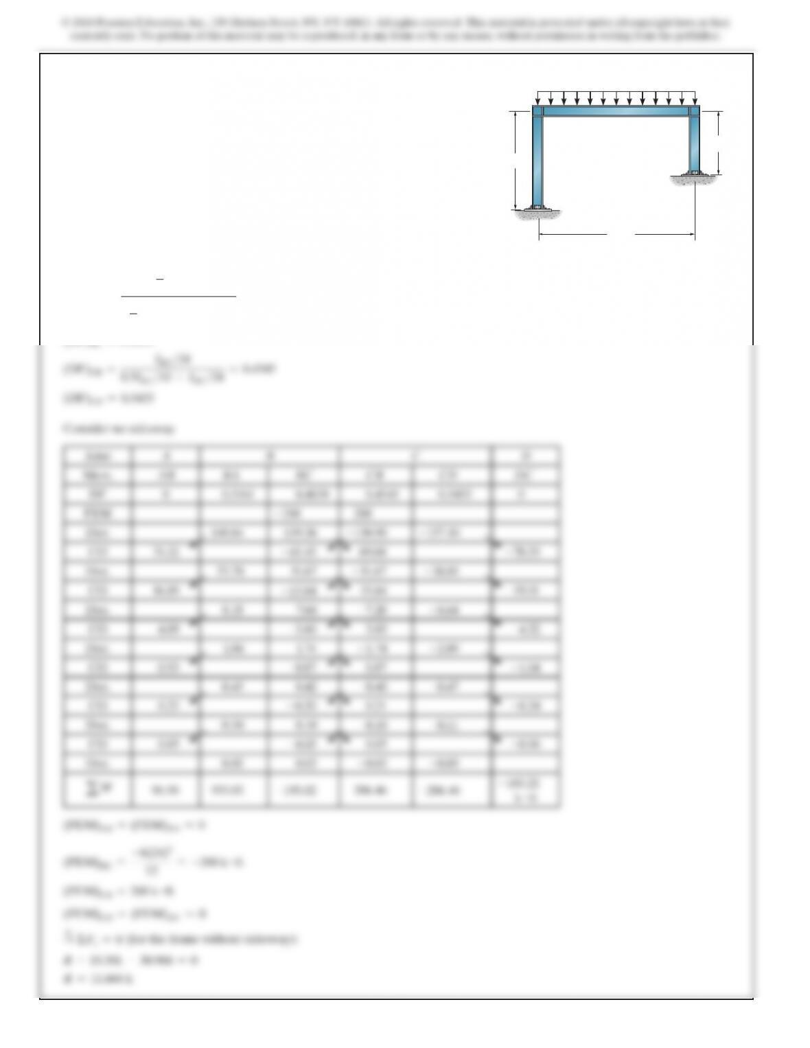
SOLUTION
(DF)AB =(DF)DC =0
(DF)BA =
a2
3 IBC
b>
15
a
2
3
IBC
b>
15 +IBC
>
24
=0.516
1
(DF)BC =0.4839
I
BC
>24
*11–24. Determine the moments acting at the ends of each
member. Assume the supports at A and D are fixed. The
moment of inertia of each member is indicated in the figure.
E=29(103)
ksi.
10 ft
15 ft
6 k>ft
IBC 5 1200 in4
IAB 5 800 in4
ICD 5 600 in4
A
BC
D
24 ft
(DF)CD =0.5455
(FEM)AB =(FEM)BA =0
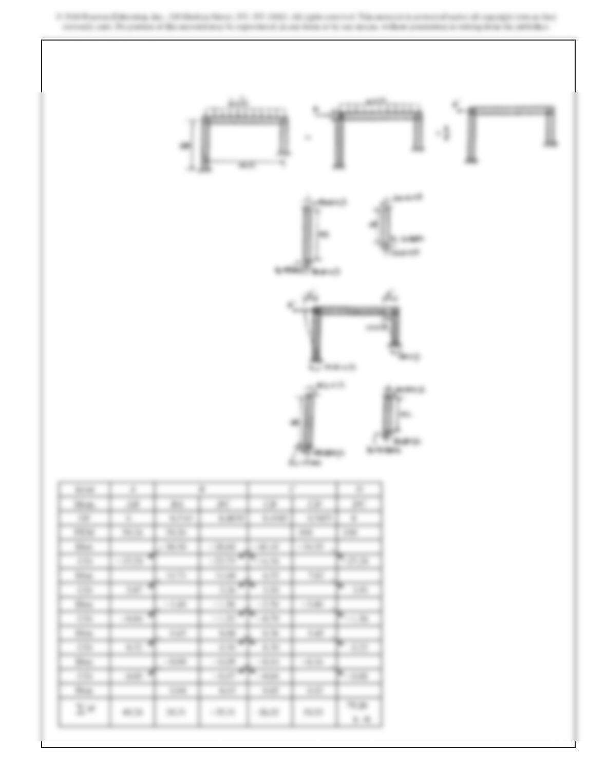
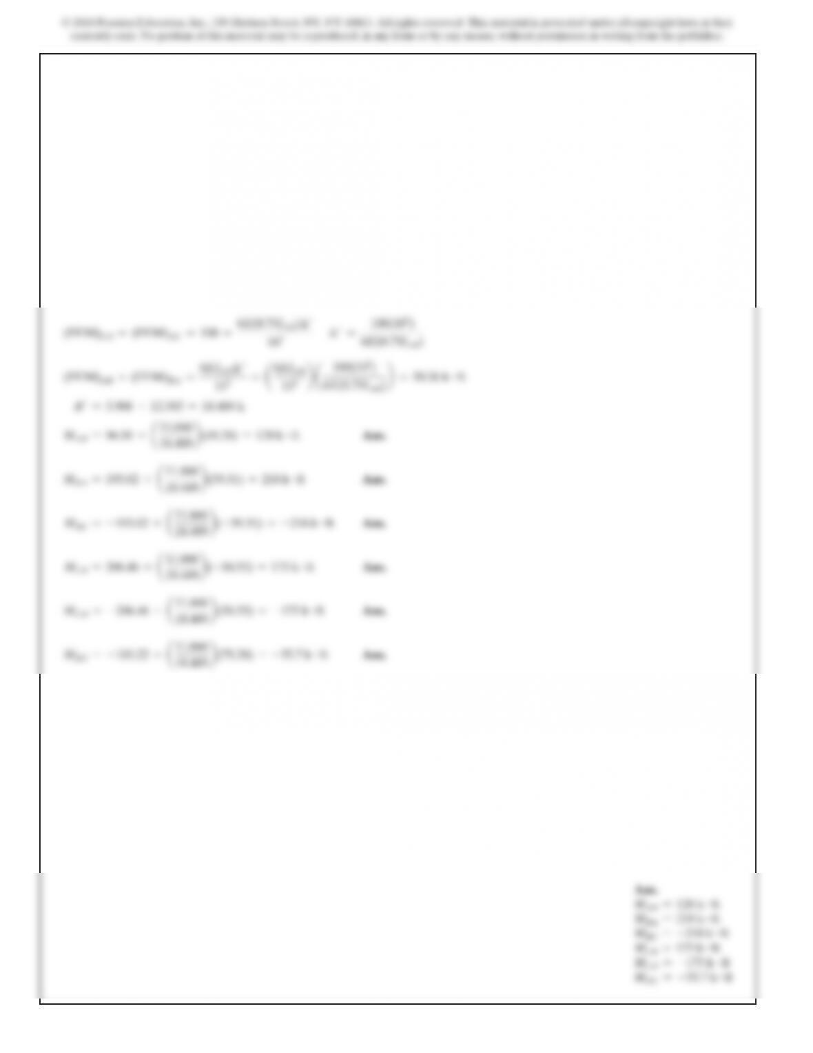
552
Ans.
MAB =128 k #ft
MBA =218 k #ft
MBC =–218 k #ft
MCB =175 k #ft
MCD =–175 k #ft
MDC =–55.7 k #ft
18.489 b
18.489 b
554
555
Ans.
MBA =24.0 k #ft
MBC =–24.0 k #ft
MCB =–24.0 k #ft
MCD =24.0 k #ft
48.14 b
48.14 b
SOLUTION
(DF)AB =(DF)DC =0
(DF)BA =(DF)CD =
I>25
I>25 +I>20
=0.444
4
(DF)BC =(DF)CB =0.5556
11–26. Determine the moments acting at the fixed supports
A and D of the battered-column frame. EI is constant.
15 ft 15 ft
20 ft
AD
20 ft
4 k>ft
BC
6 k