518
SOLUTION
(
DF)AB =0
(DF)BA =
0.75I
BC
>24
0.75IBC>24 +IBC>16
=0.333
3
(DF)BC =0.6667
(DF)CB =0
(
FEM)AB =
–0.8(24)2
12
=–38.4 k #f
t
(FEM)BA =38.4 k #ft
(
FEM)BC =–
30(16)
8
=–60.0 k
#
f
t
(FEM)CB =60.0 k #ft
Joint A B C
Mem. AB BA BC CB
DF 0 0.3333 0.6667 0
FEM
–38.4
38.4
–60.0
60.0
7.20 14.40
3.60 7.20
aM
–34.8
45.6
–45.6
67.2 k #ft
MAB =–34.8 k #ft
Ans.
MBA =45.6 k #ft
Ans.
MBC =–45.6 k #ft
Ans.
MCB =67.2 k #ft
Ans.
Ans.
MAB =–34.8 k #ft
MBA =45.6 k #ft
MBC =–45.6 k #ft
MCB =67.2 k #ft
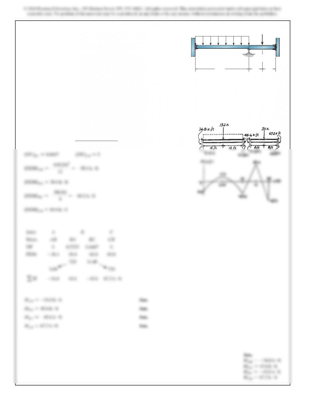
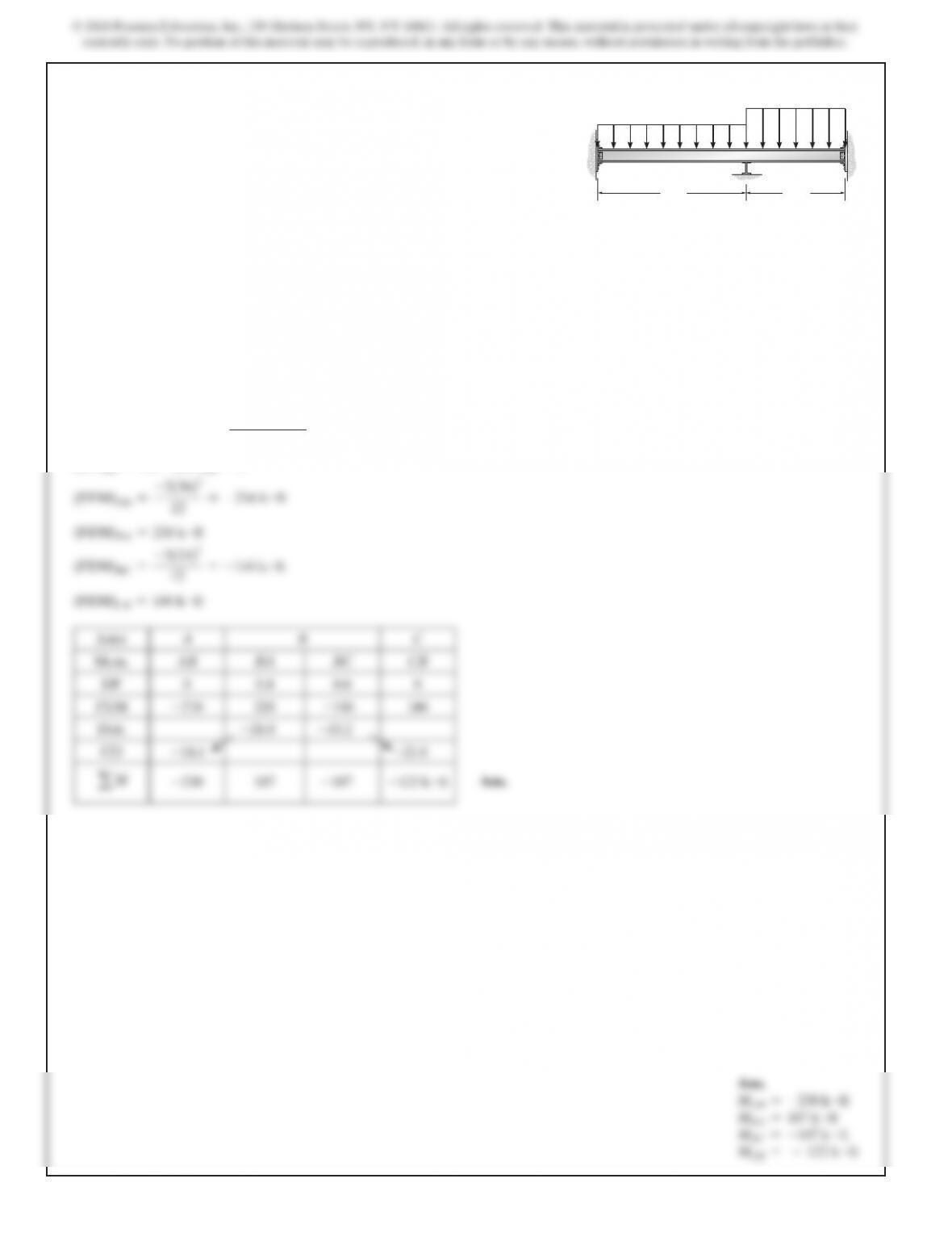
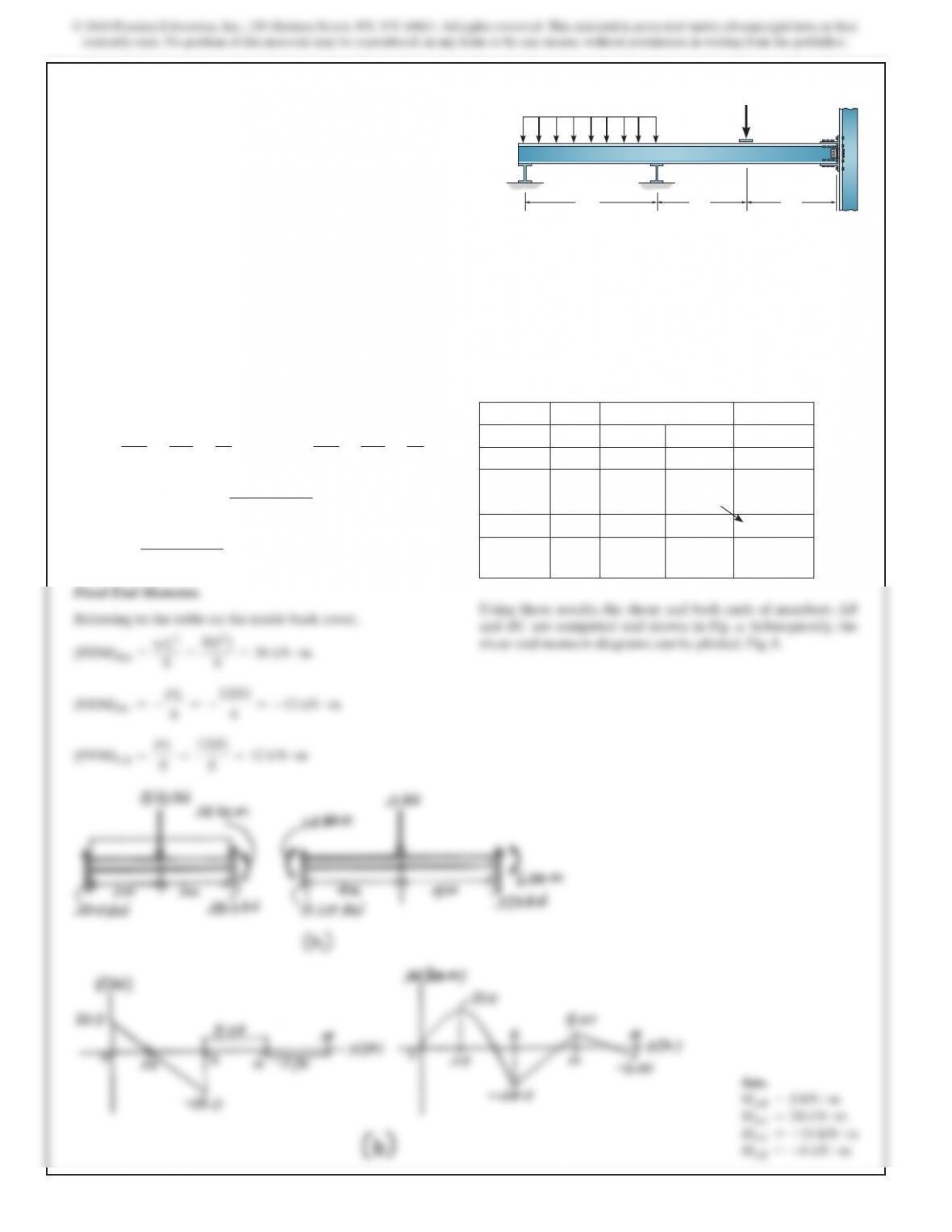
11–1. Determine the moments at A, B, and C, then draw the
moment diagram for the beam. The moment of inertia of each
span is indicated in the figure. Assume the support at B is a
roller and A and C are fixed.
E=29(103)
ksi.
24 ft 8 ft 8 ft
30 k
800 lb
>
ft
AB
C
IAB 5 900 in4
IBC 5 1200 in4
© 2018 Pearson Education, Inc., 330 Hudson Street, NY, NY 10013. All rights reserved. This material is protected under all copyright laws as they
currently exist. No portion of this material may be reproduced, in any form or by any means, without permission in writing from the publisher.
SOLUTION
F
EMAB =FEMCD =
wL2
12
=–1
6
F
EMBA =FEMDC =
wL2
12
=1
6
wL2
wL2
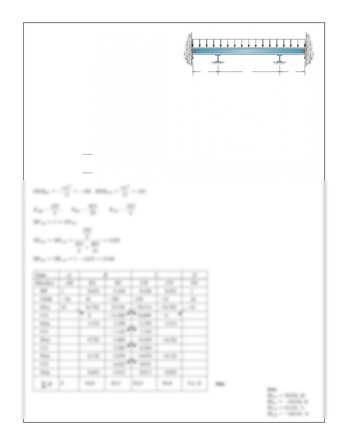
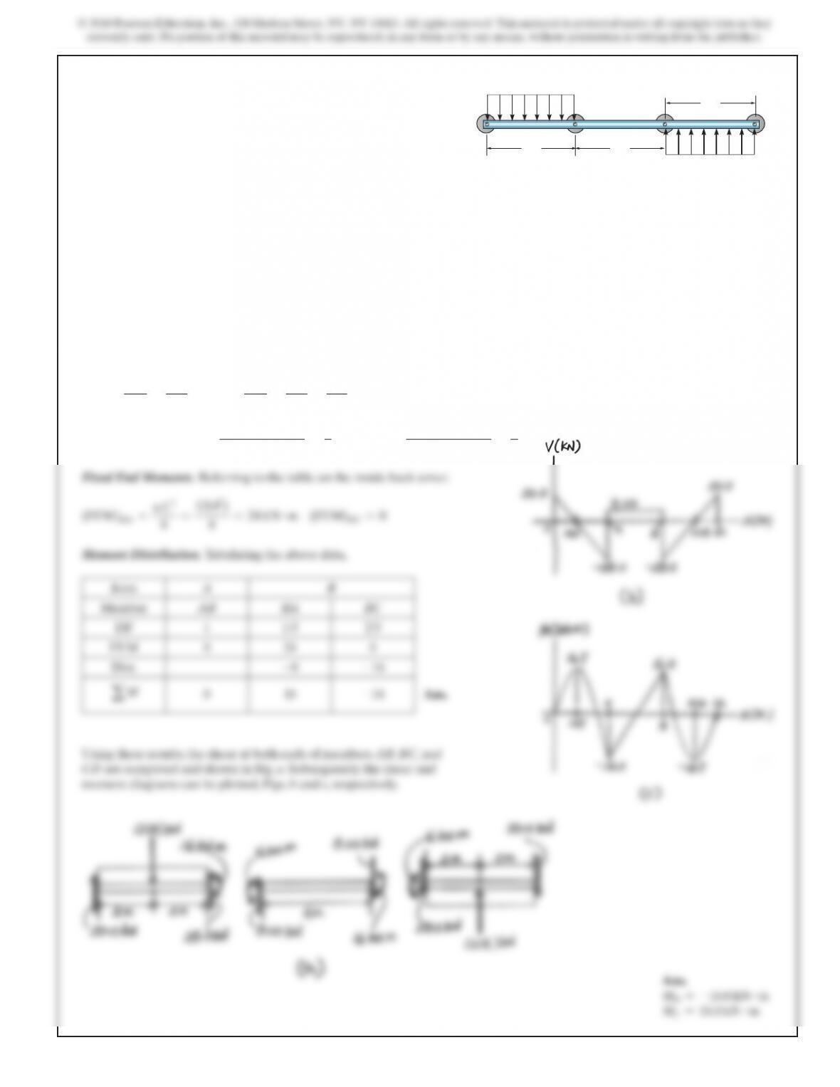
11–2. Determine the moments at B and C. EI is constant.
Assume B and C are rollers and A and D are pinned.
AB
CD
8 ft8 ft 20 ft
3 k
>
ft
F
SOLUTION
Member Stiffness Factor and Distribution Factor.
K
AB =
4EI
LAB
=
4EI
5
=0.8EI
KBC =
3EI
LBC
=
3EI
2.5
=1.2EI
(
DF)AB =0
(DF)BA =
0.8EI
0.8EI +1.2EI
=0.
4
(
DF)BC =
1.2 EI
0.8EI +1.2EI
=0.6
(DF)CB =1
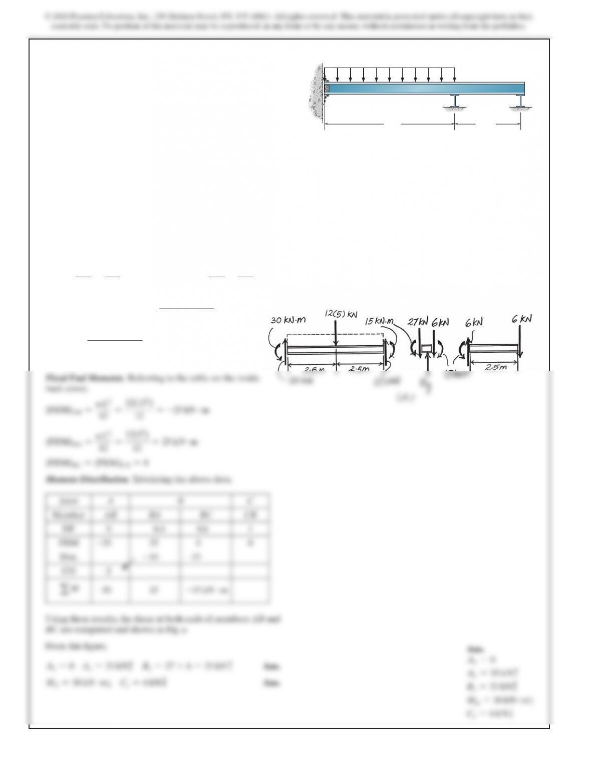
11–3. Determine the reactions at the supports. Assume A is
fixed and B and C are rollers that can either push or pull on the
beam. EI is constant.
AB
C
2.5 m
5 m
12 kN>m
(FEM)BC =(FEM)CB =0
522
SOLUTION
(
DF)AB =0
(DF)BA =
I>36
I>36 +I>24
=0.
4
(DF)BC =0.6
(DF)CB =0
(
FEM)AB =
–2(36)2
12
=–216 k #f
t
(FEM)BA =216 k #ft
(
FEM)BC =
–3(24)2
12
=–144 k #f
t
(FEM)CB =144 k #ft
Joint A B C
Mem. AB BA BC CB
DF 0 0.4 0.6 0
FEM
–216
216
–144
144
Dist.
–28.8
–43.2
CO
–14.4
–21.6
–230
–187
Ans.
MAB =–230 k #ft
MBA =187 k #ft
MBC =–187 k #ft
MCB =–122 k #ft
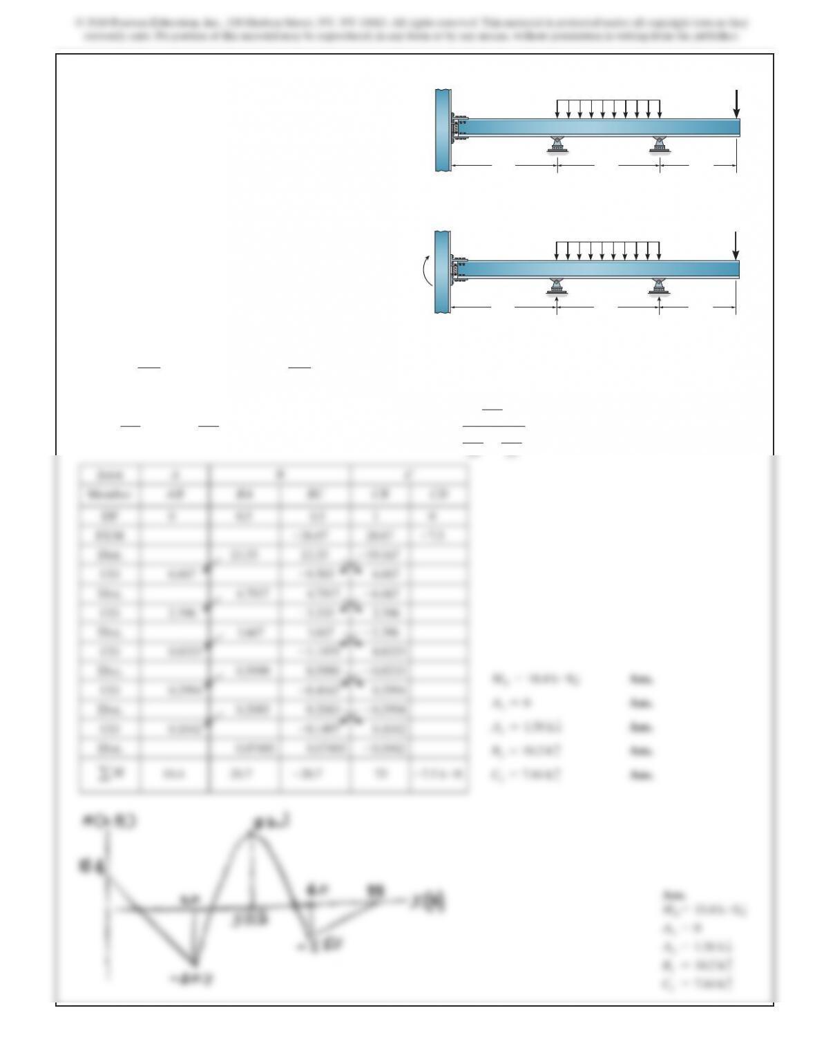
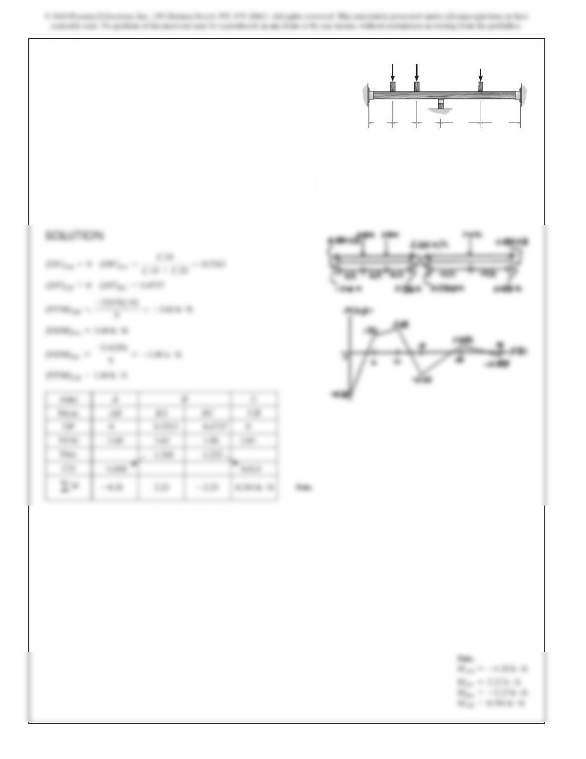
11–5. Determine the moments at A, B, and C. Assume the
support at B is a roller and A and C are fixed. EI is constant.
ABC
36 ft 24 ft
2 k
>
ft
3 k
>
ft
SOLUTION
Member Stiffness Factor and Distribution Factor.
K
AB =
3EI
LAB
=
3EI
4
KBC =
6EI
LBC
=
6EI
4
=
3EI
2
(
DF)AB =1
(DF)BA =
3EI>4
3EI>4+3EI>2
=
1
3
(DF)BC =
3EI>2
3EI>4+3EI>2
=
2
3
11–6. Determine the moments at B and C, then draw the
moment diagram for the beam. The supports at A, B, C, and D
are pins. Assume the horizontal reactions are zero. EI is
constant.
A
B
C
D
4 m
12 kN
>
m
12 kN>m
4 m
4 m
525
SOLUTION
Member Stiffness Factor and Distribution Factor.
K
AB =
3EI
LAB
=
3EI
4
KBC =
2EI
LBC
=
2EI
6
=
EI
3
(DF)AB =1
(
DF)BA =
3EI>4
3EI>4+3EI>3
=
9
13
(DF)BC =
EI>3
3EI>4+EI>3
=
4
13
Fixed End Moments. Referring to the table on the inside back cover,
(
FEM)AB =(FEM)BC =0
(FEM)BA =
wL
2
8
=
12(42)
8
=24 kN #
m
Moment Distribution. Tabulating the above data,
Joint A B
Member AB BA BC
DF 1
9
13
4
13
FEM 0 24 0
Dist.
–6.62
–7.38
aM
0
7.38
–7.38
kN #m
Due to symmetry,
MCB =7.38 kN #m
MCD =–7.38 kN #m
Ans.
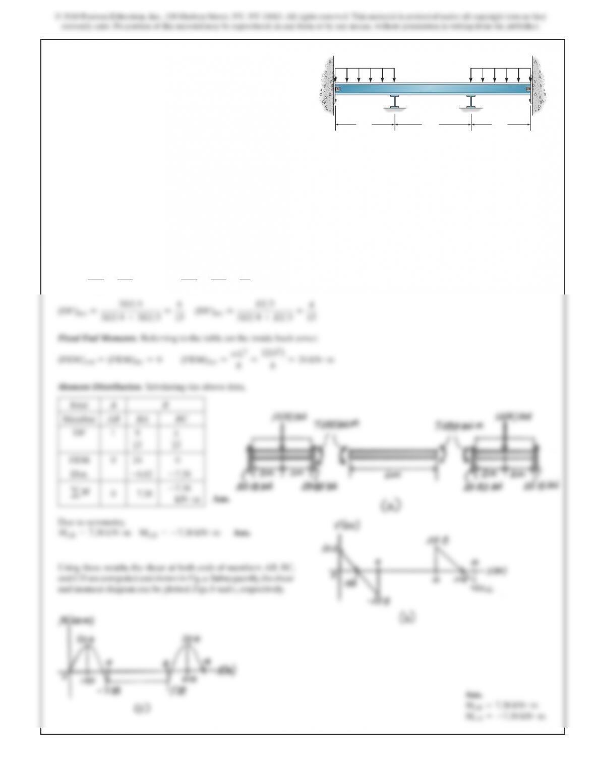
*11–8. Determine the moments at B and C, then draw the
moment diagram for the beam. Assume the supports at B and
C are rollers and A and D are pins. EI is constant.
AB
CD
4 m4 m 6 m
12 kN>m 12 kN>m
Ans.
MCB =7.38 kN #m
MCD =–7.38 kN #m
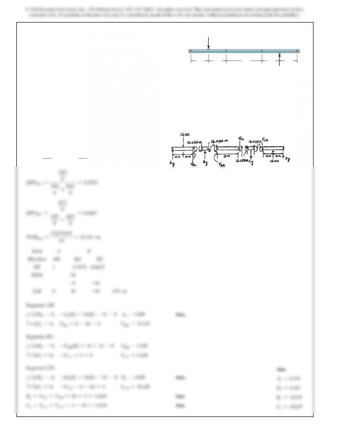
Using these results, the shear at both ends of members AB, BC,
and CD are computed and shown in Fig. a. Subsequently, the shear
and moment diagram can be plotted, Figs. b and c, respectively.
Ans.
526
SOLUTION
Use antisymmetric load and symmetric beam.
K
BA =
3EI
8
KBC =
6EI
8
(
DF)BA =
3EI
8
3EI
8
+6EI
8
=0.333
3
(
DF)BC =
6EI
8
3EI
8
+6EI
8
=0.6667
F
EMBA =
(3)(16)(8)
16
=24 kN
#m
Joint A B
Member AB BA BC
DF 1 0.3333 0.6667
FEM 24
–8
–16
ΣM
0 16
–16
kN #m
Segment AB:
a+ΣMB=0;
–Ay(8) +16(4) –16 =0
Ay=6 kN
Ans.
c
+ΣFy=0;
VBL +6–16 =0
VBL =10 kN
Segment BC:
a+ΣMC=0;
–VBR(8) +16 +16 =0
VBR =4 kN
c
+ΣFy=0;
–VCL +4=0
VCL =4 kN
Segment CD:
a+ΣMC=0;
–Dy(8) +16(4) –16 =0
Dy=6 kN
Ans.
c
+ΣFy=0;
–VCR –6+16 =0
VCR =10 kN
By=VBL +VBR =10 +4=14 kN
Ans.
Cy=VCL +VCR =4+10 =14 kN
Ans.
Ans.
Ay=6 kN
Dy=6 kN
By=14 kN
Cy=14 kN
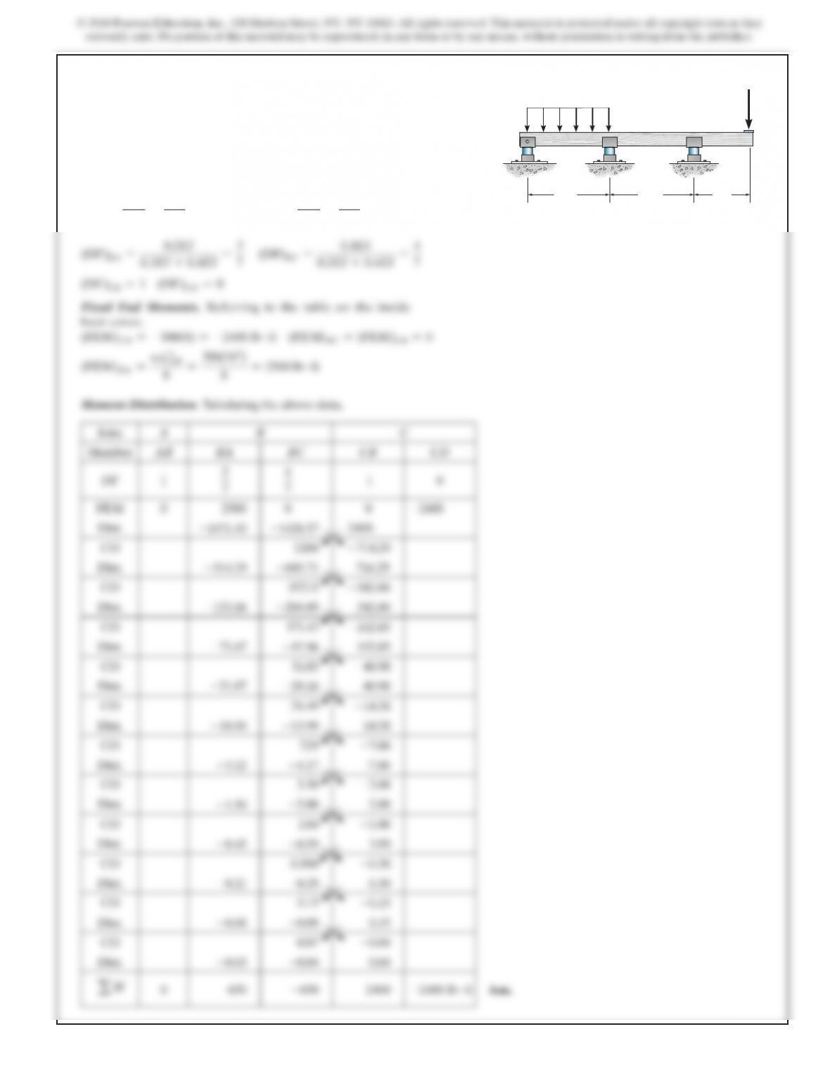
11–9. The bar is pin supported at points A, B, C, and D. If the
normal force in the bar can be neglected, determine the vertical
reaction at each pin. EI is constant.
16 kN
16 kN
4 m 4
m4
m 4 m8 m
ABC
D
527
SOLUTION
Member Stiffness Factor and Distribution Factor.
K
AB =
3EI
LAB
=
3EI
10
=0.3EI
KBC =
4EI
LBC
=
4EI
10
=0.4E
I
(
DF)BA =
0.3EI
0.3EI +0.4EI
=
3
7
(DF)BC =
0.4EI
0.3EI +0.4EI
=
4
7
(DF)CB =1
(DF)CD =0
Fixed End Moments. Referring to the table on the inside
back cover,
(FEM)CD =–300(8) =–2400 lb #ft
(FEM)BC =(FEM)CB =0
(
FEM)BA =
wL
AB
2
8
=
200(102)
8
=2500 lb
#
f
t
Moment Distribution. Tabulating the above data,
Joint A B C
Member AB BA BC CB CD
DF 1
3
7
4
7
1 0
FEM 0 2500 0 0
–2400
Dist.
–1071.43
–1428.57
2400
CO 1200
–714.29
Dist.
–514.29
–685.71
714.29
CO 357.15
–342.86
Dist.
–153.06
–204.09
342.86
CO 171.43
–102.05
Dist.
–73.47
–97.96
102.05
CO 51.03
–48.98
Dist.
–21.87
–29.16
48.98
CO 24.49
–14.58
Dist.
–10.50
–13.99
14.58
CO 7.29
–7.00
Dist.
–3.12
–4.17
7.00
CO 3.50
–2.08
Dist.
–1.50
–2.00
2.08
CO 1.04
–1.00
Dist.
–0.45
–0.59
1.0 0
CO 0.500
–0.30
Dist.
–0.21
–0.29
0.30
CO 0.15
–0.15
Dist.
–0.06
–0.09
0.15
CO 0.07
–0.04
Dist.
–0.03
–0.04
0.04
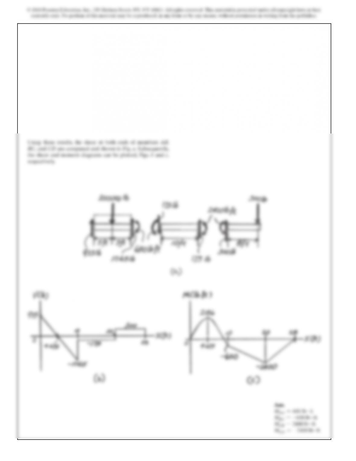
11–10. Determine the moments at B and C, then draw the
moment diagram for the beam. Assume the supports at B and
C are rollers and A is a pin. EI is constant.
10 ft 10 ft 8 ft
C
B
AD
200 lb>ft
300 lb
SOLUTION
Member Stiffness Factor and Distribution Factor.
K
BA =
3EI
LBA
=
3EI
6
=
EI
2
KBC =
4EI
LBC
=
4EI
8
=
EI
2
(
DF)AB =1
(DF)BA =
EI>2
EI>2+EI>2
=0.
5
(
DF)BC =
EI>2
EI>2+EI>2
=0.5
(DF)CB =
0
8
8
Moment Distribution. Tabulating the above data,
Joint A B C
Member AB BA BC CB
DF 1 0.5 0.5 0
FEM 0 36
–12
12
Dist.
–12
–12
CO
–6
a
M0 24
–24
6 kN #m
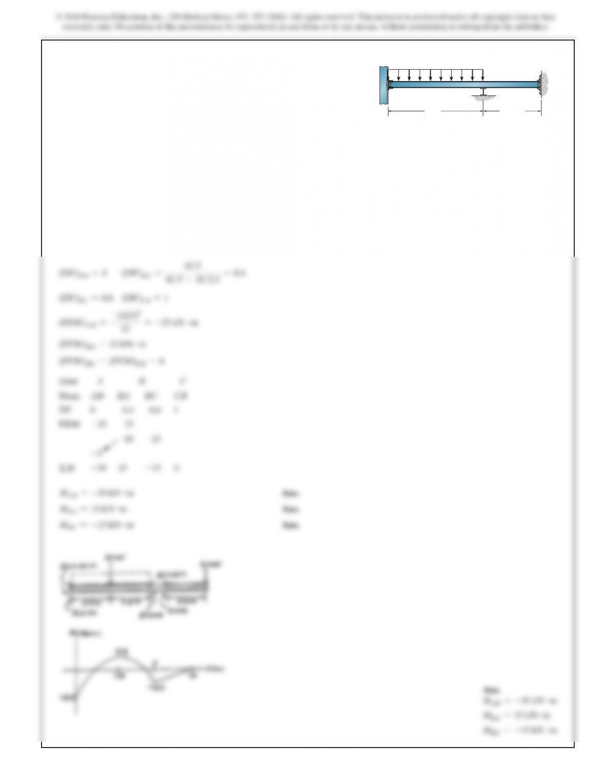
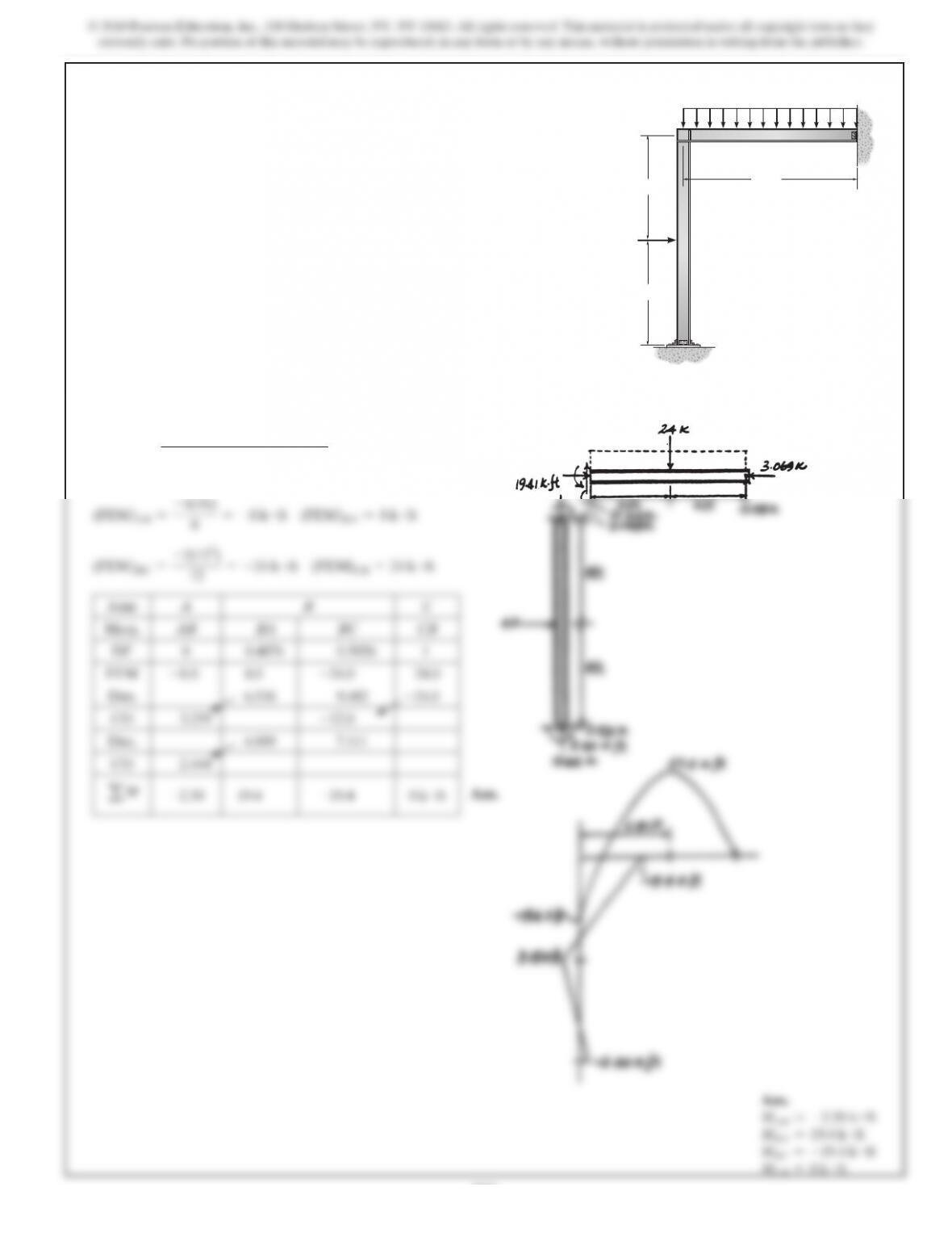
*11–12. Determine the moments at B and C, then draw the
moment diagram for the beam. Assume C is a fixed support. EI
is constant.
6 m 4 m
4 m
B
A
C
8 kN>m
12 kN
Ans.
531
SOLUTION
(DF)AB =0
(
DF)BA =
4(0.6875I
BC
)>16
4(0.6875IBC)>16 +3IBC>12
=0.407
4
(DF)BC =0.5926
(DF)CB =1
(
FEM)AB =
–4(16)
8
=–8 k
#
ft
(FEM)BA =8 k
#
f
t
(
FEM)BC =
–2(122)
12
=–24 k #ft
(FEM)CB =24 k #f
t
Joint A B C
Mem. AB BA BC CB
DF 0 0.4074 0.5926 1
FEM
–8.0
8.0
–24.0
24.0
Dist. 6.518 9.482
–24.0
CO 3.259
–12.0
Dist. 4.889 7.111
CO 2.444
aM
–2.30
19.4
–19.4
0 k #ft
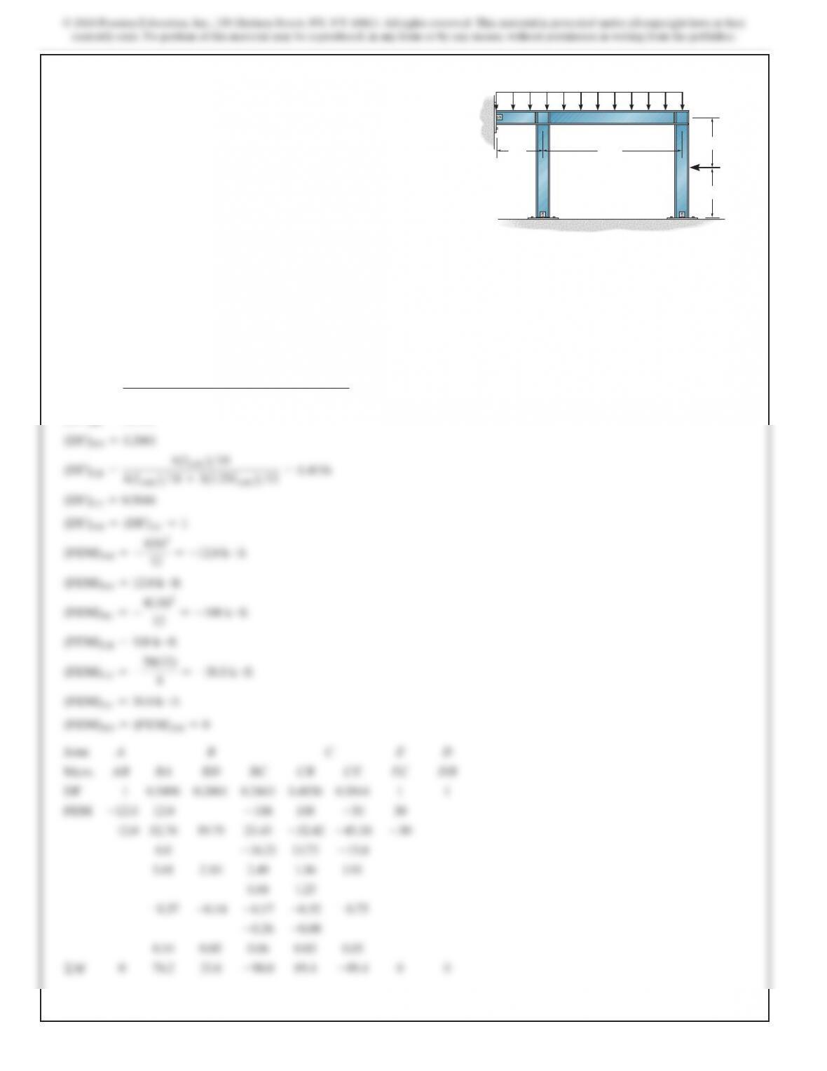
11–13. Determine the moments at the ends of each member
of the frame. Assume the joint at B is fixed, C is pinned, and A
is fixed. The moment of inertia of each member is listed in the
figure.
E=29(103)
ksi.
2 k>ft
A
4
k
8 ft
8 ft
B
12 ft
C
IBC 5 800 in4
IAB 5 550 in4
Ans.
MAB =–2.30 k #ft
MBA =19.4 k #ft
MBC =–19.4 k #ft
MCB =0 k #ft
Ans.
SOLUTION
(DF)AB =1
(
DF)BA =
3(I
ABC
)>6
3(IABC)>6+4(IABC)>18 +3(0.75IABC)>12
=0.549
6
(DF)BC =0.2443
(DF)BD =0.2061
4(I
ABC
)>18
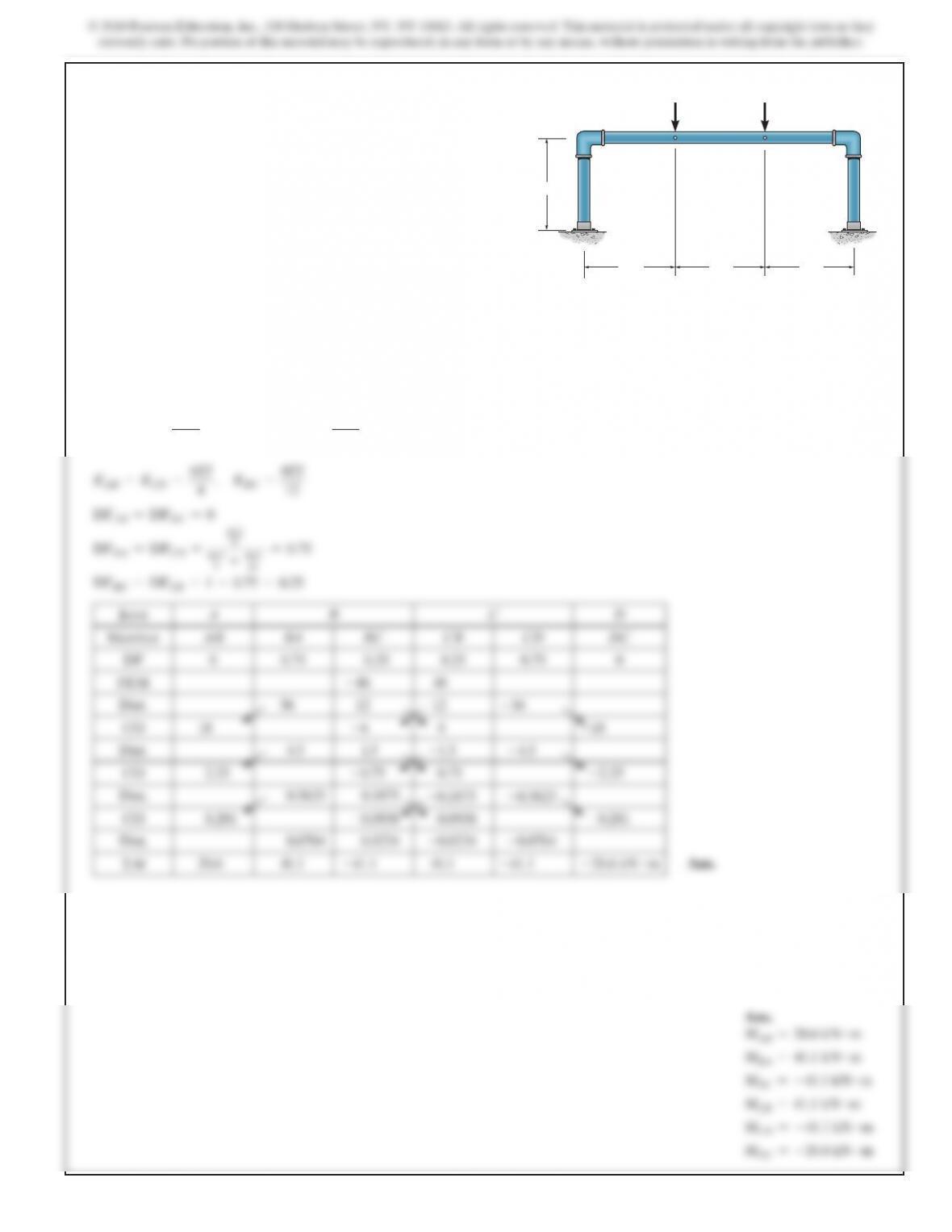
11–14. Determine the internal moments acting at each joint.
Assume A, D, and E are pinned and B and C are fixed joints.
The moment of inertia of each member is listed in the figure.
Take
E=29(103)
ksi.
4 k>ft
6 ft 18 ft
ABC
DE
IABC 5 800 in4
IBD 5 600 in4
ICE 5 1000 in4
6 ft
6 ft
20 k
(
4(IABC)>18 +3(1.25IABC)>12
(DF)CE =0.5844
(DF)DB =(DF)EC =1
(FEM)BD =(FEM)DB =0
533
MAB =0
MBA =76.2 k #ft
MBD =21.8 k #ft
MDB =0
Ans.
MAB =0
MBA =76.2 k #ft
MBD =21.8 k #ft
MBC =–98.0 k #ft
MCB =89.4 k #ft
MCE =–89.4 k #ft
MEC =0
MDB =0
11–14. (Continued)
SOLUTION
(DF)AB =(DF)DC =0
(
DF)BA =(DF)CD =
I>15
I>15 +I>24
=0.615
4
(DF)BC =(DF)CB =0.3846
(FEM)AB =(FEM)BA =0
(
FEM)BC =
–8(24)2
12
=–384 k #f
t
(FEM)CB =384 k #ft
(FEM)CD =(FEM)DC =0
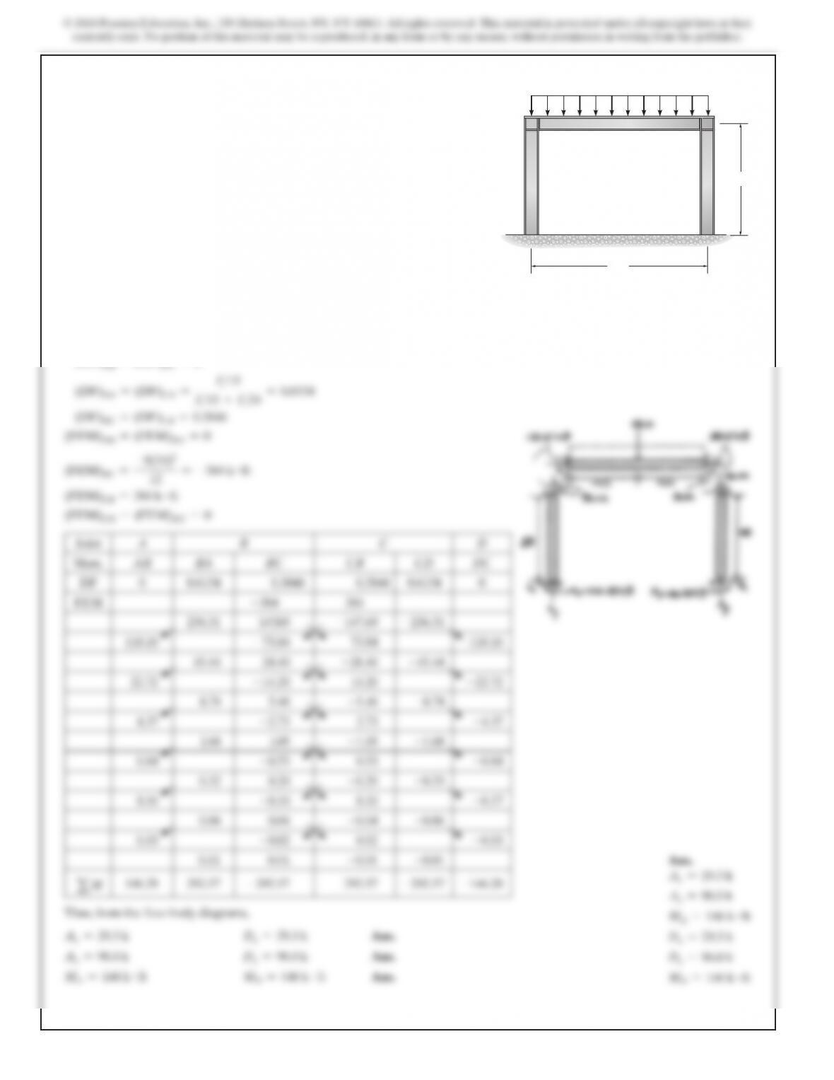
11–15. Determine the reactions at A and D. Assume the
supports at A and D are fixed and B and C are fixed connected.
EI is constant.
8 k>ft
A
BC
D
15 ft
24 ft
536
SOLUTION
Member Stiffness Factor and Distribution Factor.
K
AD =
4EI
L
=
4EI
12
=
EI
3
KDC =KDB =
3EI
L
=
3EI
12
=
EI
4
(
DF)AD =0
(DF)DA =
EI>3
EI>3+EI>4+EI>4
=0.
4
(
DF)DC =(DF)DB =
EI>4
EI>3+EI>4+EI>4
=0.3
(DF)CD =(DF)BD =
1
Fixed End Moments. Referring to the table on the inside
back cover,
(
FEM)AD =–wL
2
12
=–
4(122)
12
=–48 k #f
t
(
FEM)DA =
wL
2
12
=–
4(122)
12
=48 k #f
t
(
FEM)DC =–wL
2
8
=–
4(122)
8
=–72 k #f
t
(FEM)CD =(FEM)BD =(FEM)DB =0
Moments Distribution. Tabulating the above data,
Joint A D C B
Member AD DA DB DC CD BD
DF 0 0.4 0.3 0.3 1 1
FEM
Dist.
–48
48
9.60
0
7.20
–72
7.20
0 0
CO 4.80
a
–43.2
–64.8
k#ft
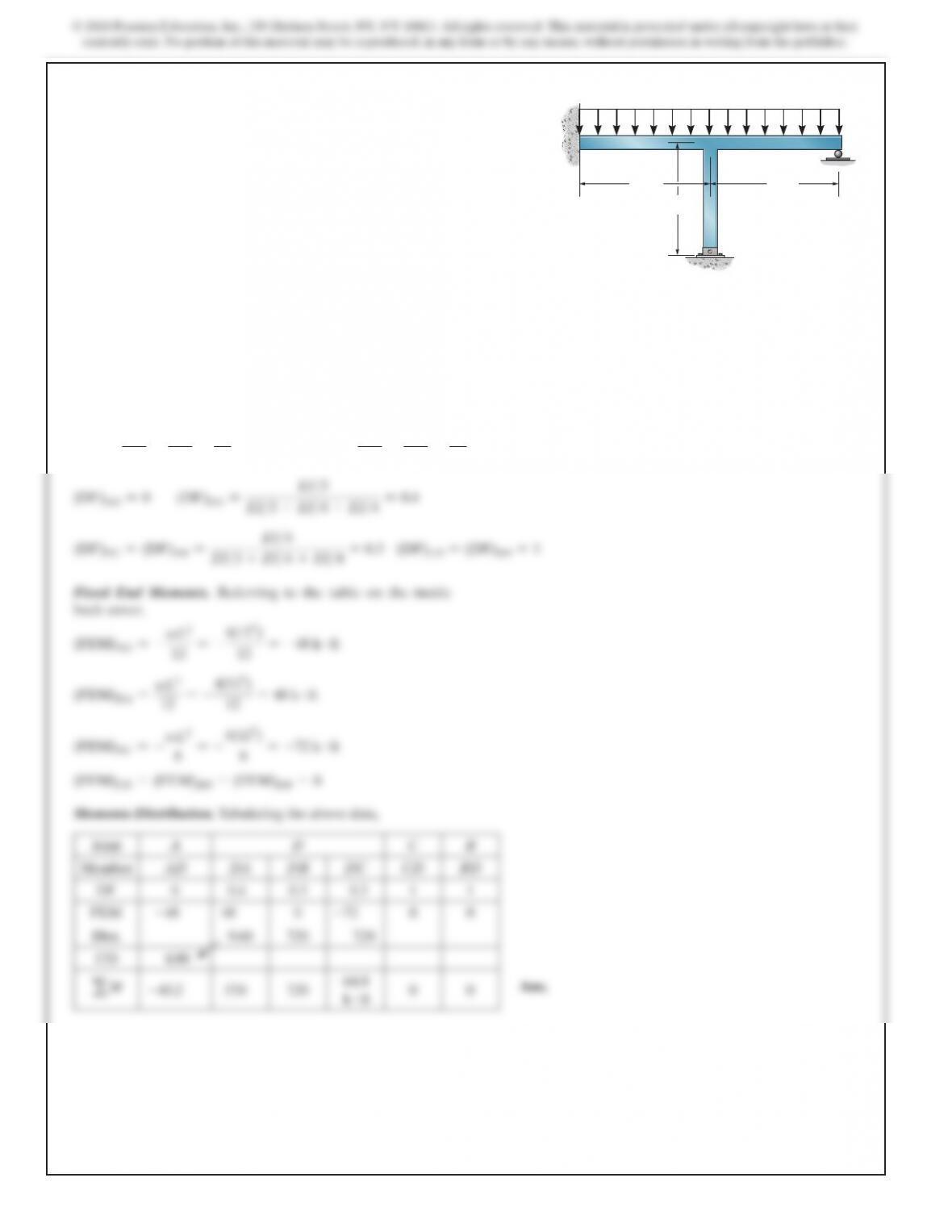
11–17. Determine the moments at the fixed support A and
joint D and then draw the moment diagram for the frame.
Assume B is pinned.
A
B
D
4 k>ft
12 ft 12 ft
12 ft
C
537
11–17. (Continued)
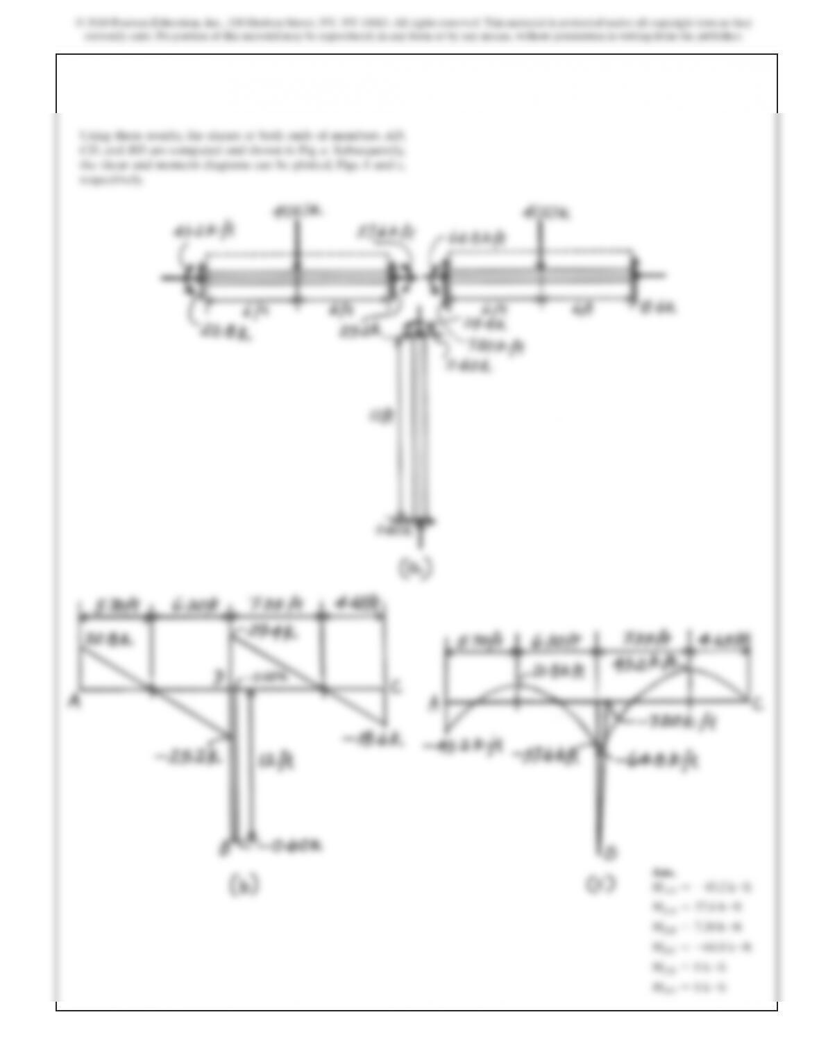
Ans.
MAD =–43.2 k #ft
MDA =57.6 k #ft
MDB =7.20 k #ft
MDC =–64.8 k #ft
MCD =0 k #ft
MBD =0 k #ft
Using these results, the shears at both ends of members AD,
CD, and BD are computed and shown in Fig. a. Subsequently,
the shear and moment diagrams can be plotted, Figs. b and c,
respectively.