SOLUTION
1
FEM
2
AB =
1112521622
192
=–51.5625 kN #
m
1
FEM
2
BA =
512521622
192
=23.4375 kN #
m
–51152182
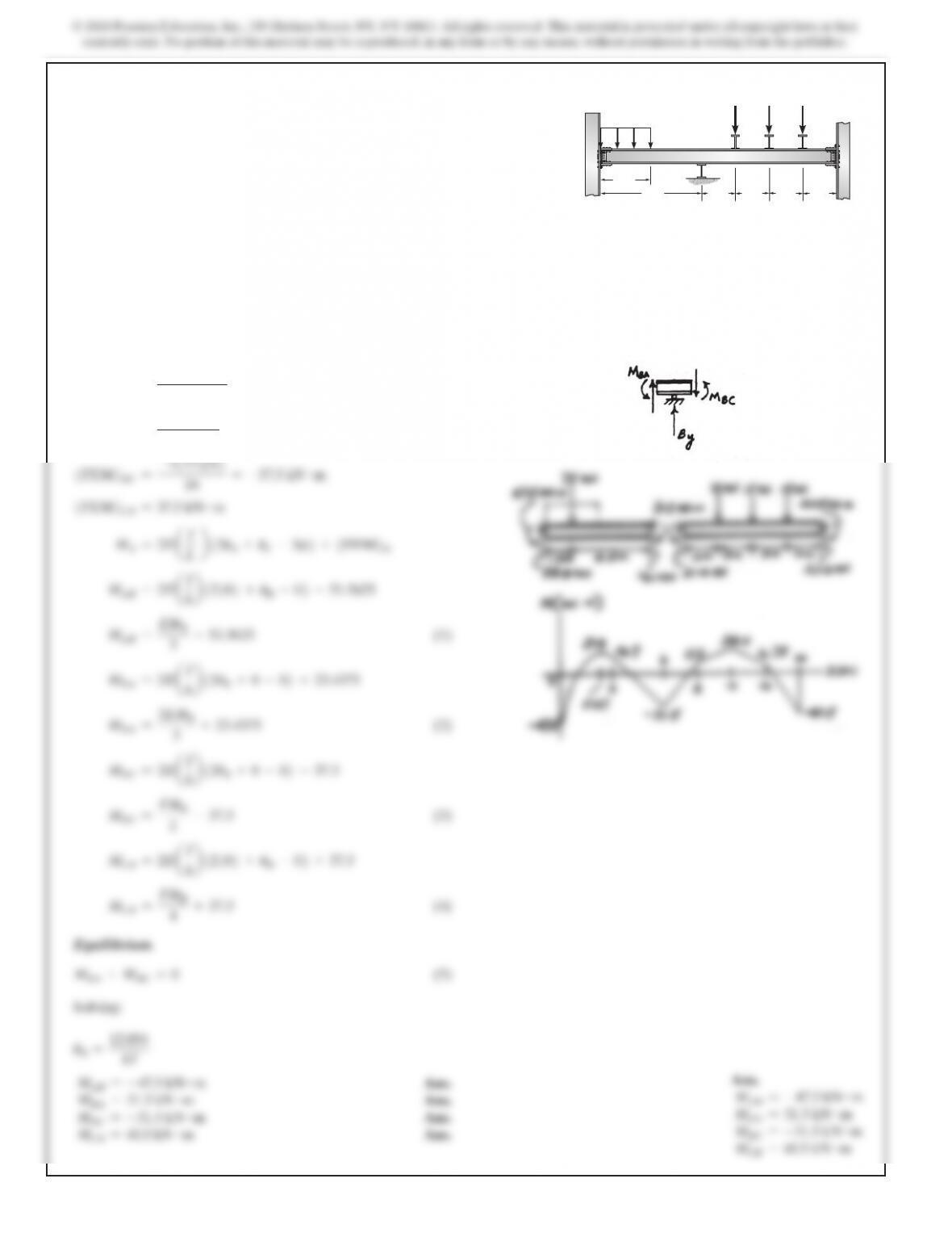
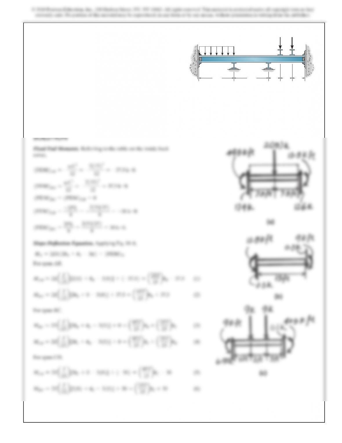
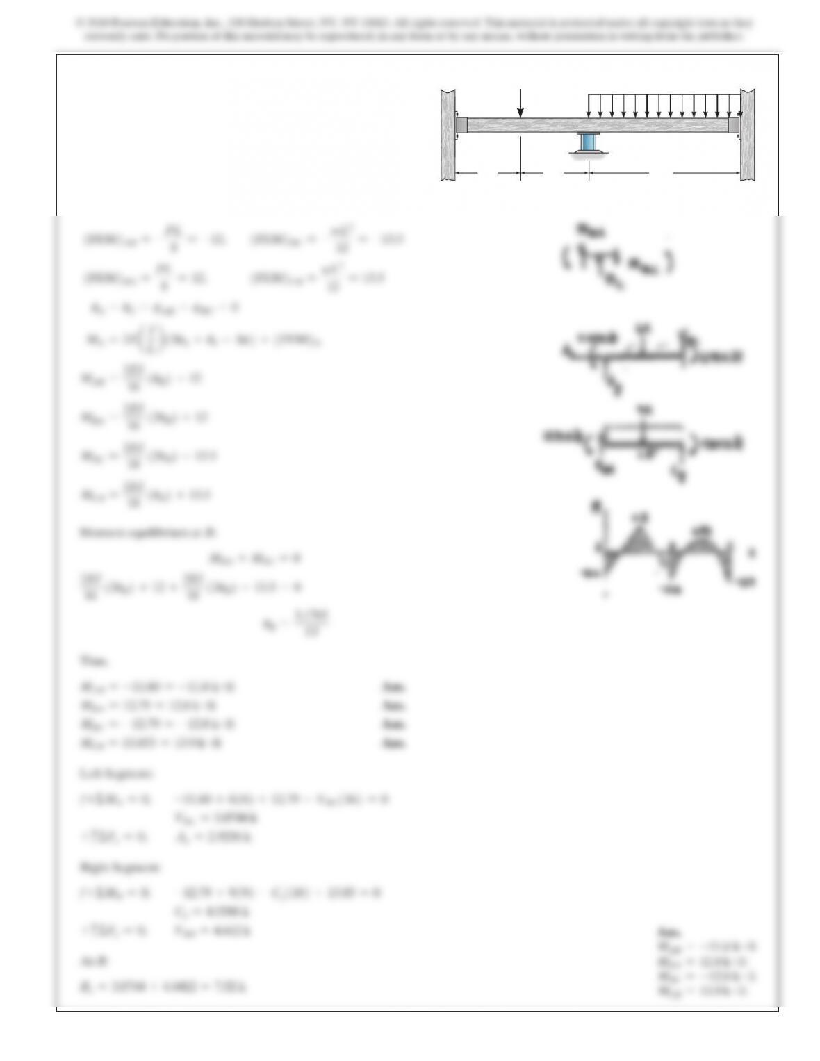
10–1. Determine the moments at the supports, then draw the
moment diagram. Assume B is a roller and A and C are fixed.
EI is constant.
3 m
6 m
A
25 kN>m
2 m 2 m 2 m 2 m
15 kN 15 kN 15 kN
BC
483
15 b
15 b
484
10–2. (Continued)
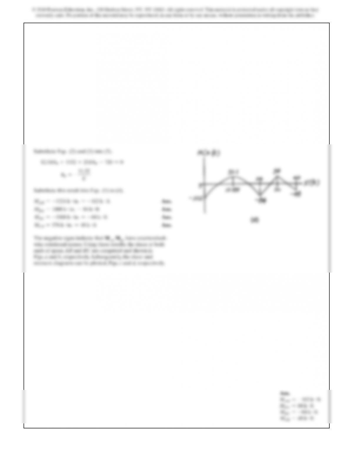
MAB =–49.5 k #ft
MBA =13.5 k #ft
MBC =–13.5
k#ft
MCB =9 k #ft
MCD =–9 k #ft
MDC =40.5 k #ft
Equilibrium. At support B,
MBA +MBC =0
a4EI
15 b
uB+37.5 +
a4EI
15 b
uB+
a2EI
15 b
uC=
0
a8EI
15 b
uB+
a2EI
15 b
uC=–37.
5
At support C,
MCB +MCD =0
a4EI
15 b
uC+
a2EI
15 b
uB+
a4EI
15 b
uC–30 =
0
a8EI
15 b
uC+
a2EI
15 b
uB=3
0
Solving Eqs. (7) and (8),
u
C=
78.75
EI
uB=–
90
EI
Substitute these results into Eqs. (1) to (6).
MAB =–49.5 k #ft
Ans.
MBA =13.5 k #ft
Ans.
MBC =–13.5 k #ft
Ans.
MCB =9 k #ft
Ans.
MCD =–9 k #ft
Ans.
MDC =40.5 k #ft
Ans.
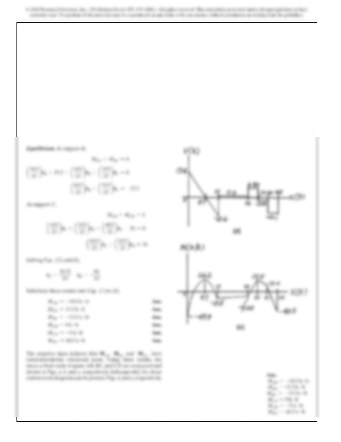
The negative signs indicate that MAB, MBC, and MCD have
counterclockwise rotational sense. Using these results, the
shear at both ends of spans AB, BC, and CD are computed and
shown in Figs. a, b, and c, respectively. Subsequently, the shear
485
SOLUTION
Fixed End Moments. Referring to the table on the inside back
cover,
1FEM2AB =0
1FEM2BA =0
1FEM2CD =0
1FEM2DC =0
1
FEM
2
BC =–wL
2
12
=–
201322
12
=–15 kN #
m
1
FEM
2
CB =
wL
2
12
=
201322
12
=15 kN #
m
15 b
3b
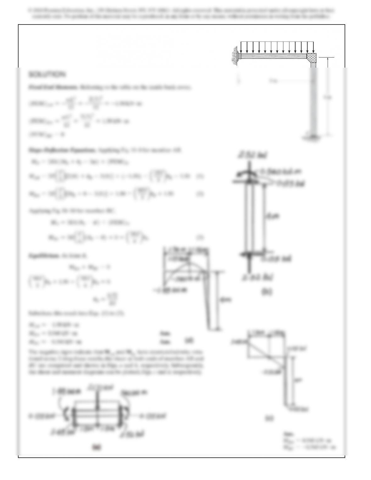
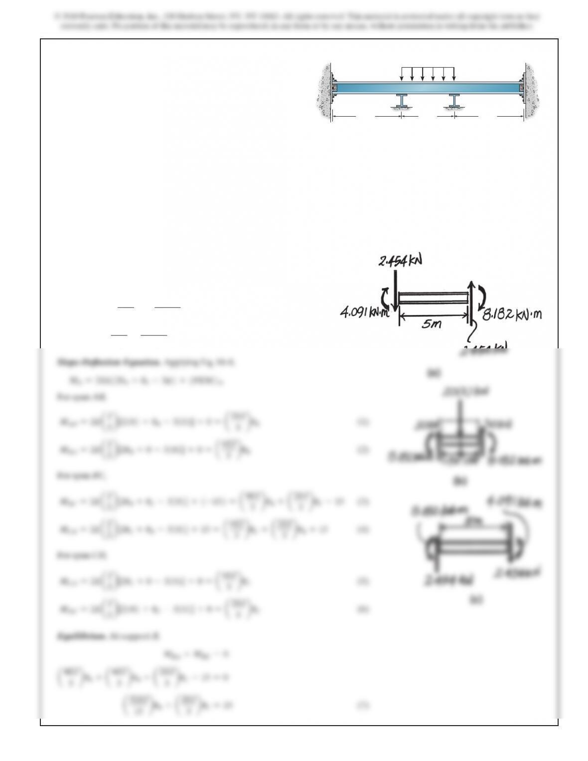
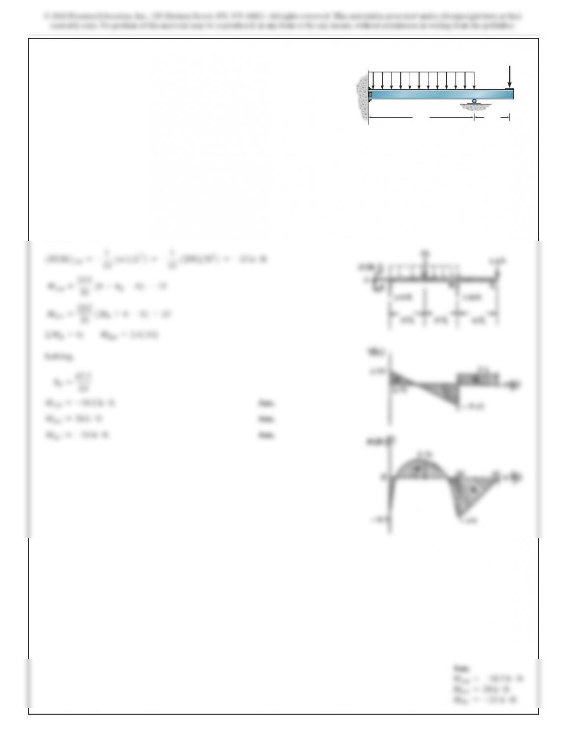
10–3. Determine the moments at A, B, C, and D, then draw
the moment diagram for the beam. Assume the supports at A
and D are fixed and B and C are rollers. EI is constant.
AB
5 m
CD
3 m 5 m
20 kN>m
488
SOLUTION
M
AB =
2EI
8
1
0+uB–0
2
+0=
EI
4
u
B
M
BA =
2EI
8
1
2uB+0–0
2
+0=
EI
2
u
B
M
BC =
2EI
8
1
2uB+0–0
2
–20 =
EI
2
uB–2
0
M
CB =
2EI
8
1
0+uB–0
2
+20 =
EI
4
uB+2
0
MBA +MBC =0
Solving,
u
B=
20
EI
MAB =5 kN #m
Ans.
MBA =10 kN #m
Ans.
MBC =–10 kN #m
Ans.
MCB =25 kN #m
Ans.
Ans.
u
B=
20
EI
MAB =5 kN #m
MBA =10 kN #m
MBC =–10 kN #m
MCB =25 kN #m
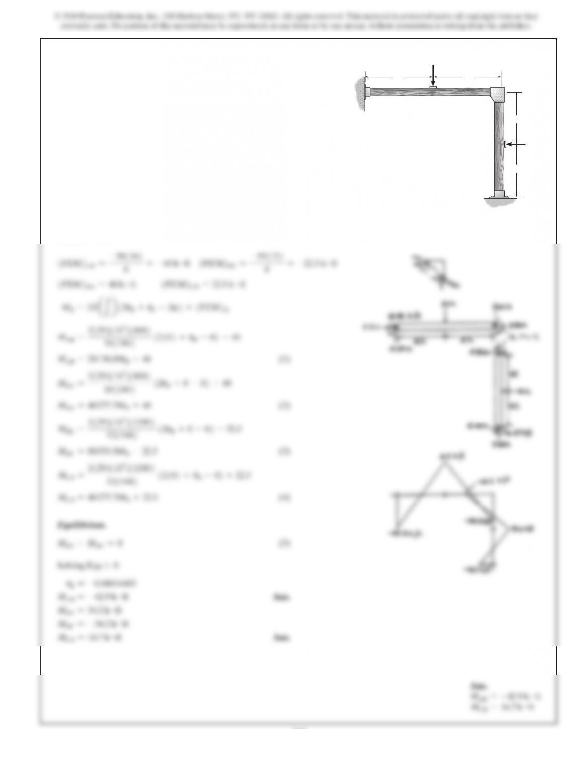
10–5. Determine the moments at A, B, and C, then draw the
moment diagram for the beam. Assume the supports at A and
C are fixed. EI is constant.
20 kN15 kN
8 m4 m4 m
A
BC
490
SOLUTION
MN=2E
aI
Lb1
2uN+uF–3c
2
+
1
FEM
2N
MAB =
2EI
20
1
2
1
0
2
+uB–0
2
–
412022
12
MBA =
2EI
20
1
2uB+0–0
2
+
412022
12
MBC =
2EI
15
1
2uB+uC–0
2
+
0
MCB =
2EI
15
1
2uC+uB–0
2
+
0
MN=3E
aI
Lb1
uN–c
2
+
1
FEM
2N
MCD =
3EI
16
1
uC–0
2
–
3112216
16
Equilibrium.
MBA +MBC =0
MCB +MCD =0
Solving,
u
C=
178.08
EI
u
B=–
336.60
EI
MAB =–167 k #ft
Ans.
MBA =66.0 k #ft
Ans.
MBC =–66.0 k #ft
Ans.
MCB =2.61 k #ft
Ans.
MCD =–2.61 k #ft
Ans.
Ans.
MAB =–167 k #ft
MBA =66.0 k #ft
MBC =–66.0 k #ft
MCB =2.61 k #ft
MCD =–2.61 k #ft
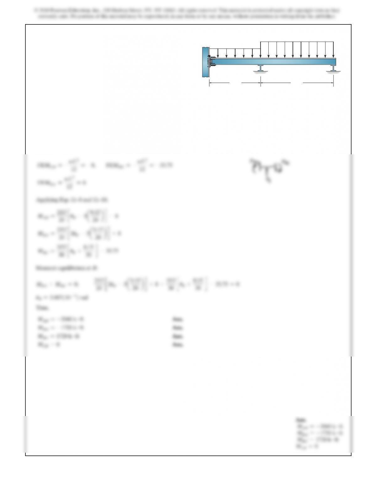
10–7. Determine the moments at each support, then draw
the moment diagram. Assume A is fixed. EI is constant.
A
4 k>ft
20 ft 15 ft 8 ft 8 ft
BCD
12 k
492
SOLUTION
1
FEM
2
AB =–
1
12
1
w
21
L2
2
=–
1
12
1
200
21
302
2
=–15 k
#
ft
MAB =
2EI
30
1
0+uB–0
2
–1
5
MBA =
2EI
30
1
2uB+0–0
2
+1
5
ΣMB=0;
MBA =2.41102
Solving,
uB=
67.5
EI
MAB =–10.5 k #ft
Ans.
MBA =24 k #ft
Ans.
MBC =–24 k #ft
Ans.
Ans.
MAB =–10.5 k #ft
MBA =24 k #ft
MBC =–24 k #ft
10–9. Determine the moments at A and B, then draw the
moment diagram for the beam. EI is constant. 200 lb>ft
2400 lb
30 ft 10 ft
A
BC
494
SOLUTION
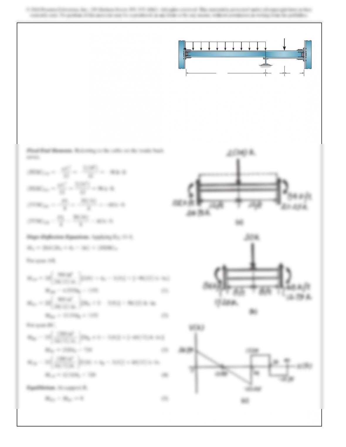
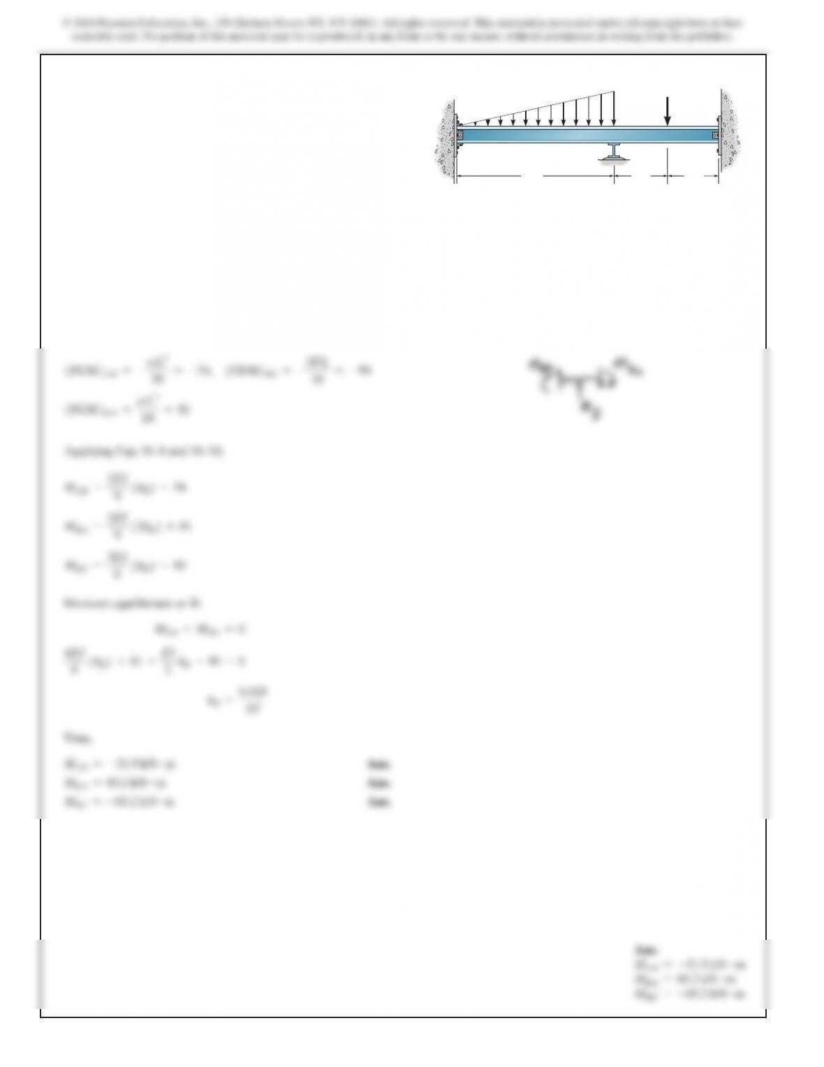
10–11. Determine the moments at A, B, and C, then draw
the moment diagram for the beam. The moment of inertia of
each span is indicated in the figure. Assume the support at B is
a roller and A and C are fixed.
E=29(103)
ksi.
A
24 ft 8 ft 8 ft
B
C
2 k>ft
30 k
IAB 5 900 in4
IBC 5 1200 in4
495
Ans.
MAB =–102 k #ft
MBA =84 k #ft
MBC =–84 k #ft
MCB =48 k #ft
MAB =–1224 k #in. =–102 k #ft
MBA =1008 k #in. =84 k #ft
496
SOLUTION
1
FEM
2
AB =–
wL2
30
=–54,
1
FEM
2
BC =–
3PL
16
=–9
0
1
FEM
2
BA =
wL2
20
=8
1
Applying Eqs. 10–8 and 10–10,
M
AB =
2EI
9
1
uB
2
–5
4
M
BA =
2EI
9
1
2uB
2
+8
1
MBC =
3EI
6
1
uB
2
–9
0
Moment equilibrium at B:
MBA +MBC =0
4EI
9
1
uB
2
+81 +
EI
2
uB–90 =
0
u
B=
9.529
EI
Thus,
MAB =–51.9 kN #m
Ans.
MBA =85.2 kN #m
Ans.
MBC =–85.2 kN #m
Ans.
Ans.
MAB =–51.9 kN #m
MBA =85.2 kN #m
MBC =–85.2 kN #m
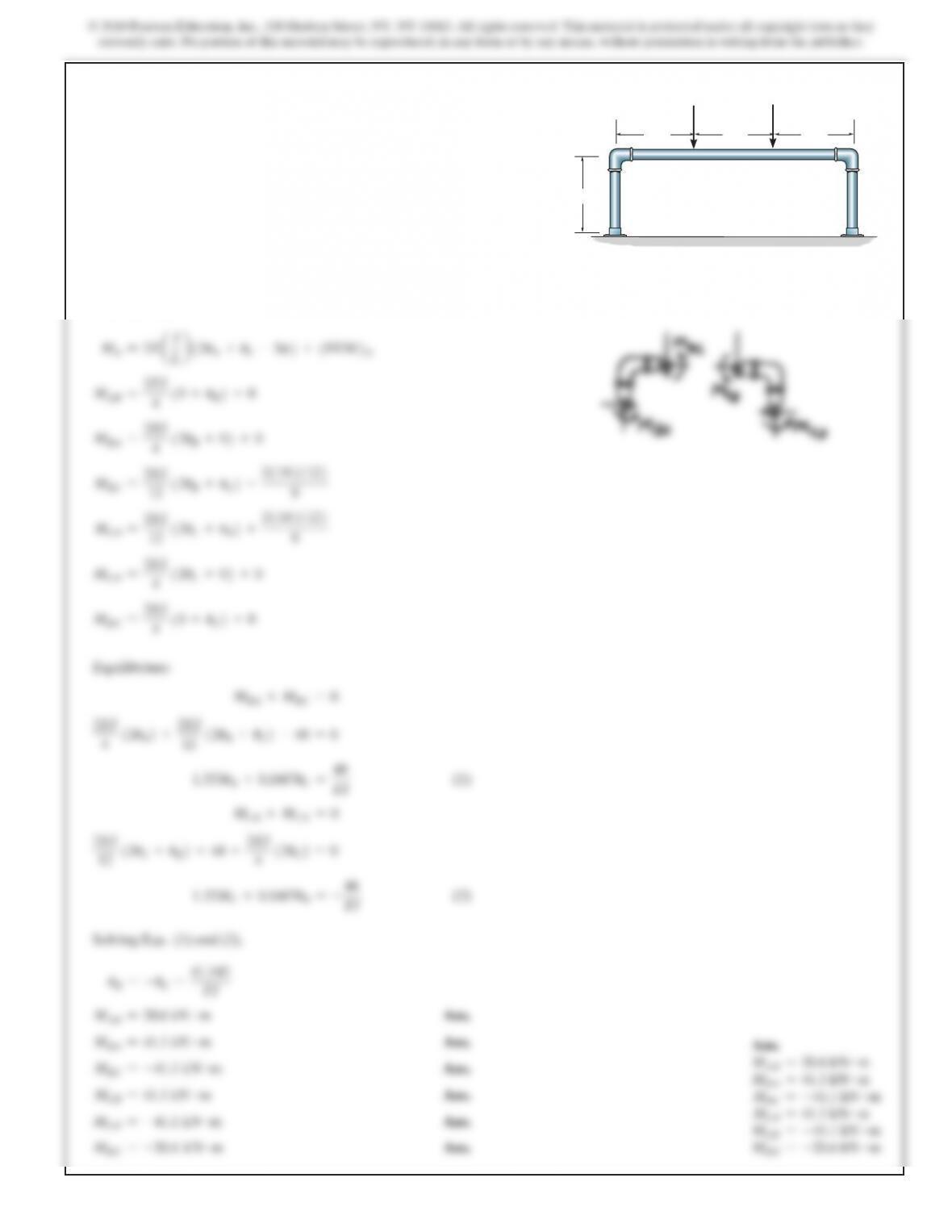
*10–12. Determine the moments acting at A and B. Assume
A is fixed supported, B is a roller, and C is a pin. EI is
constant.
B
AC
3 m
9 m 3 m
80 kN
20 kN>m