
672
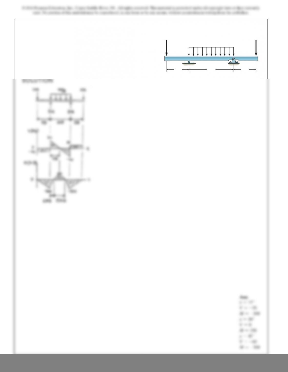
7–58.
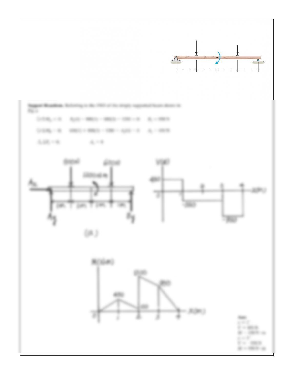
Draw the shear and bending-moment diagrams for each of the
two segments of the compound beam.
A
CD
150 lb/ft
B
10 ft 4ft
2ft2ft
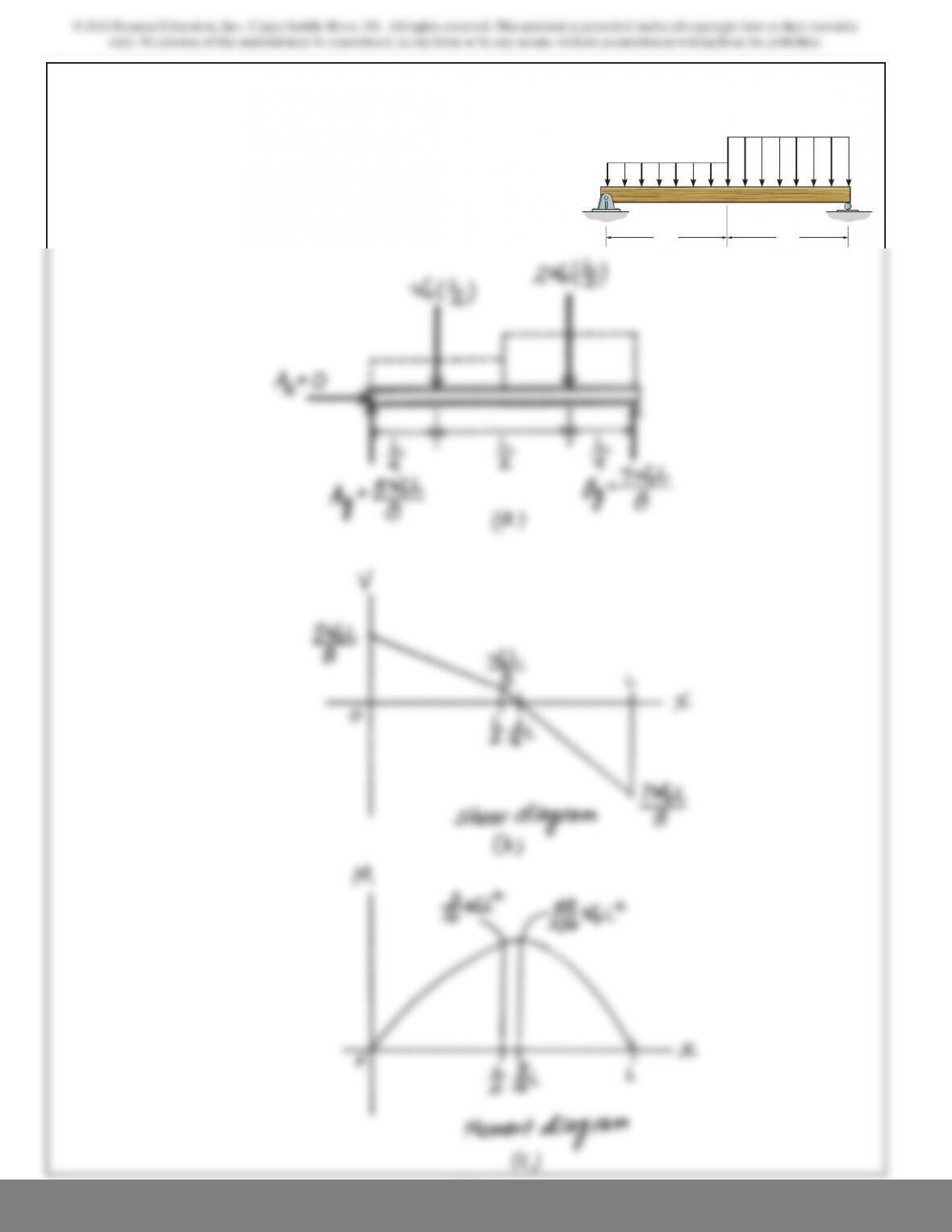
SOLUTION
From FBD (b),
a
Shear and Moment Functions: Member AB.
For [FBD (c)],
Ans.
a
Ans.
M=5875x–75.0x
2
6lb
#
ft
M+150xax
2b–875x=0+©M=0;
V=5875 –150x6lb
875 –150x–V=0+c©F
y
=0;
0◊x<12 ft
D
y
+918.75 –1225 =0D
y
=306.25 lb+c©F
y
=0;
1225162–C
y
182=0C
y
=918.75 lb+©M
D
=0;
A
y
+1225 –2100 =0A
y
=875 lb+c©F
y
=0;
7–59.
Draw t
h
e s
h
ear an
d
moment
di
agrams for t
h
e
b
eam.
A
BC
9ft 4.5ft
30 lb/ft
180lbft

675
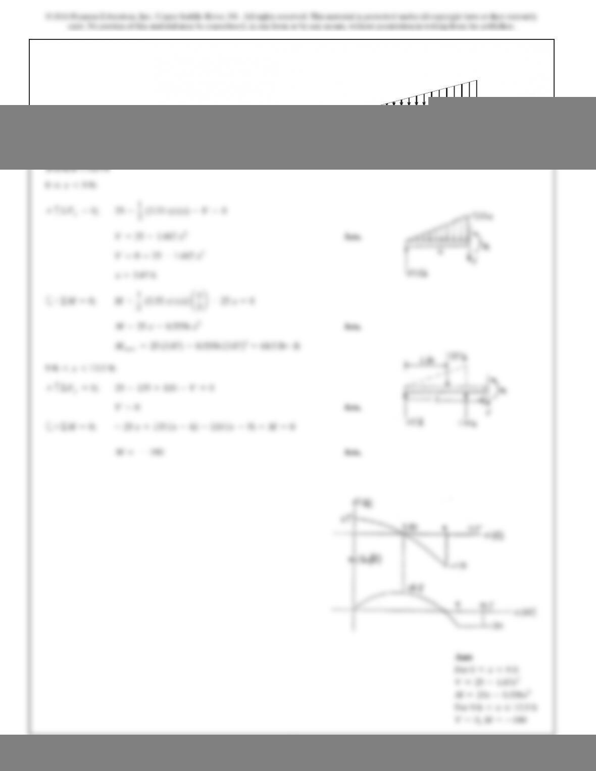
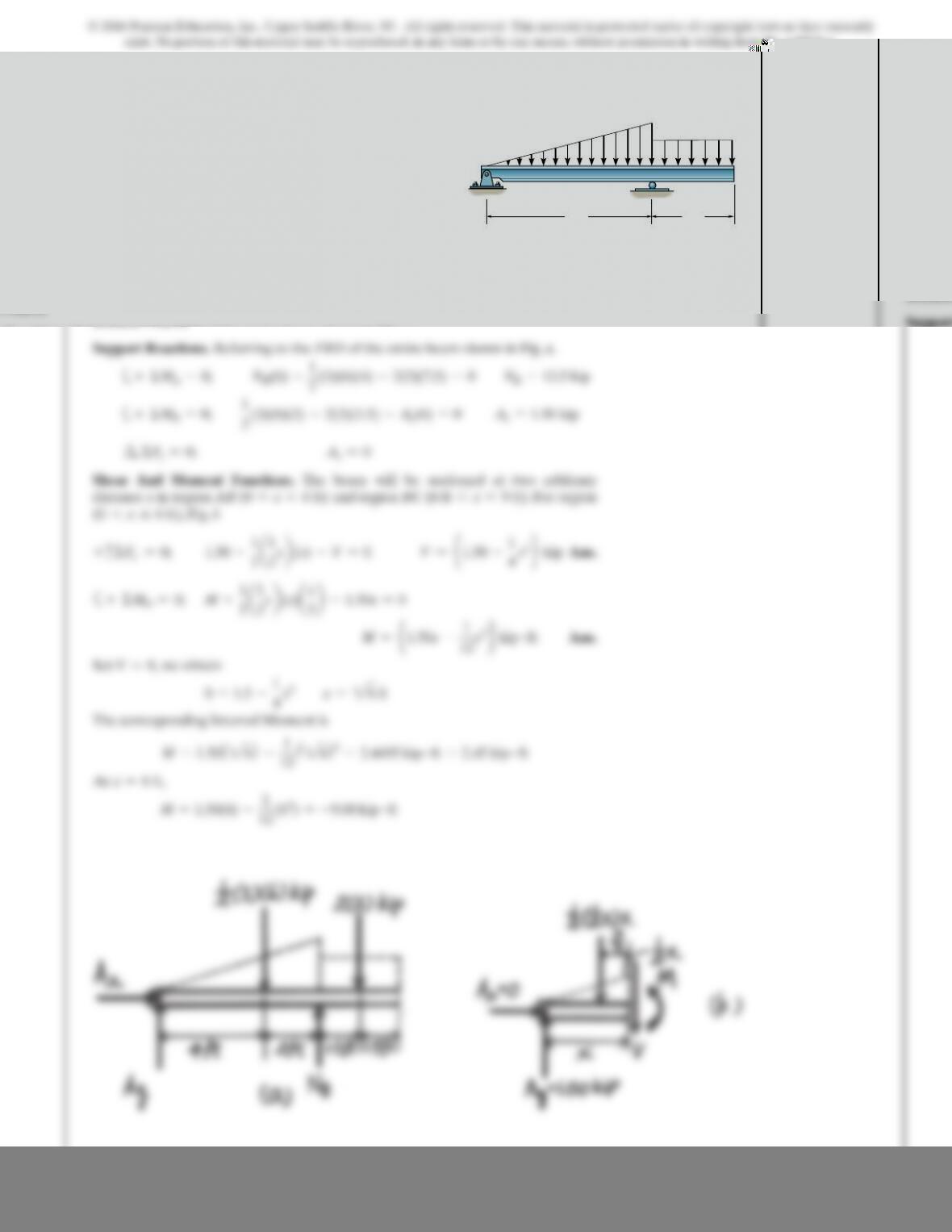
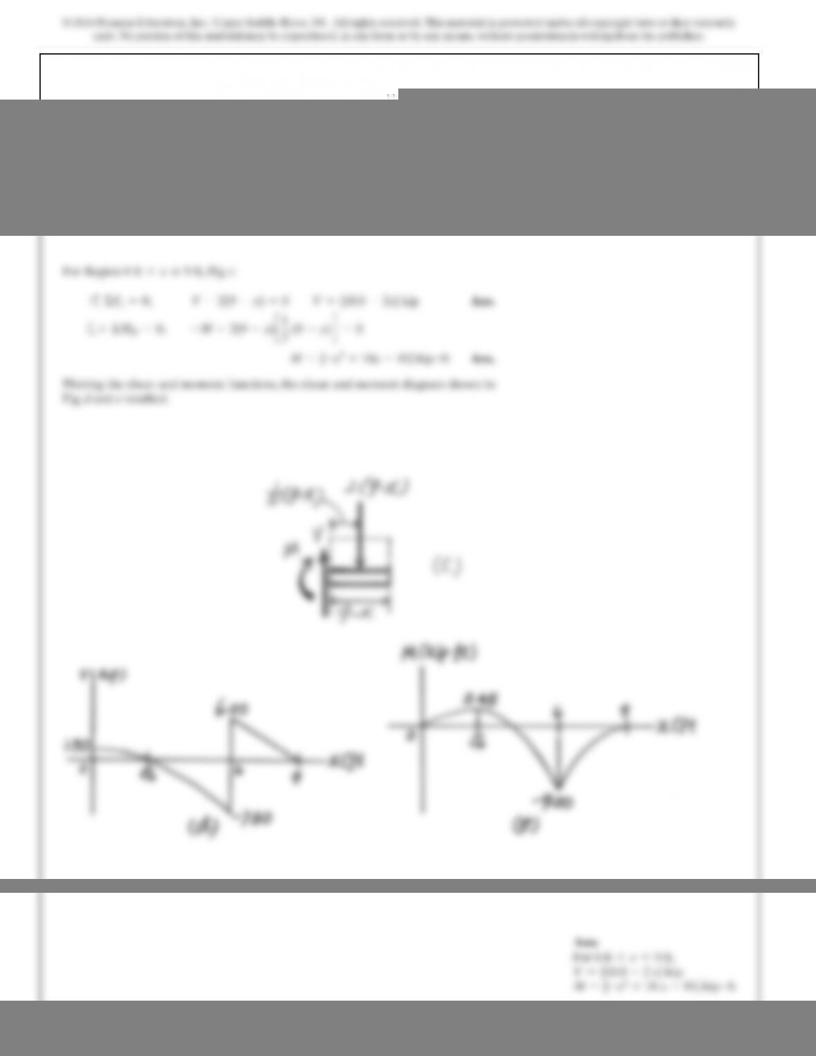
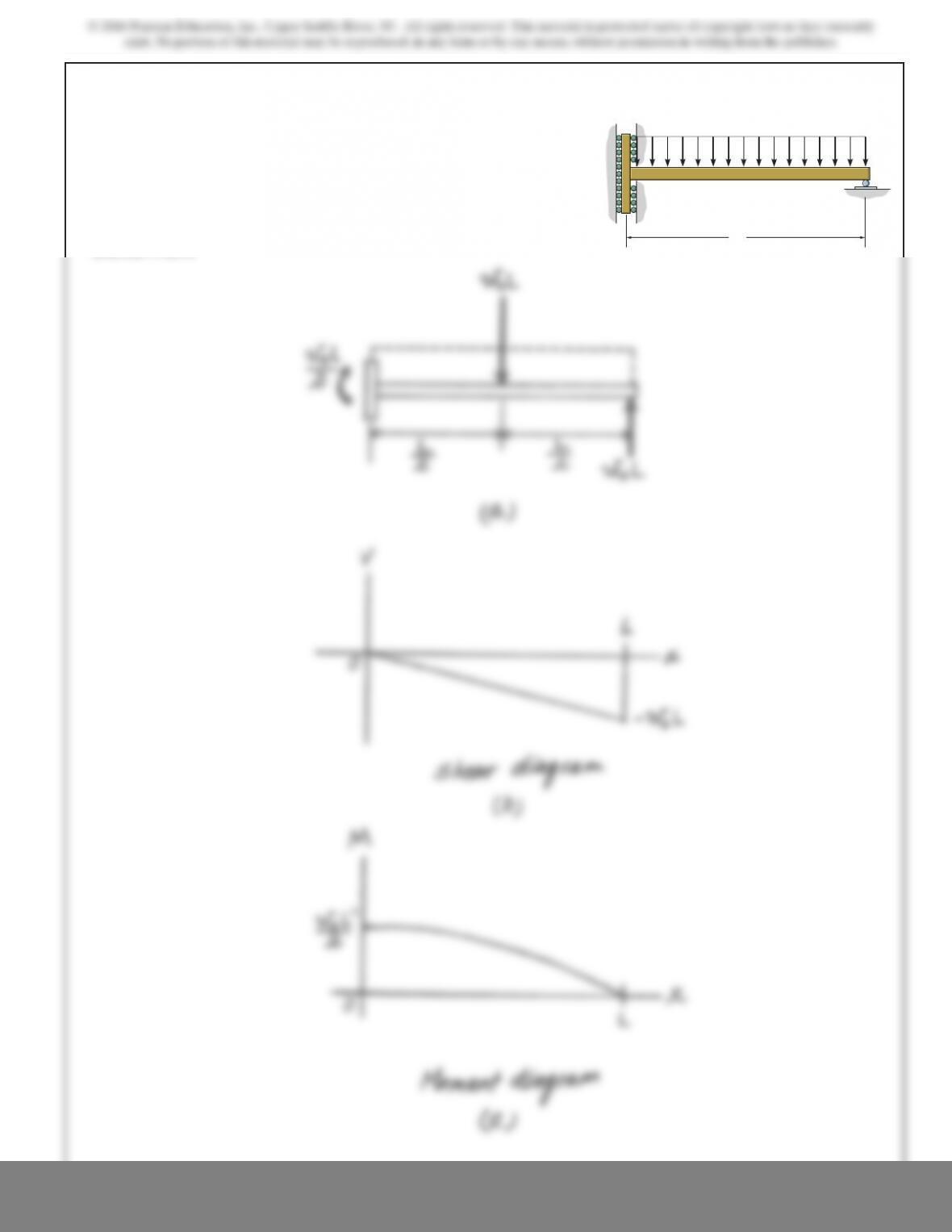
*7–60.
The shaft is supported by a smooth thrust bearing at Aand a
smooth journal bearing at B. Draw the shear and moment
diagrams for the shaft.
SOLUTION
free-body diagram of the beam’s segment sectioned through the arbitrary points
within these two regions are shown in Figs. band c.
Region ,Fig. b
(1)
a
(2)
Region ,Fig. c
(3)
a(4)
The shear diagram shown in Fig. dis plotted using Eqs. (1) and (3). The location at
which the shear is equal to zero is obtained by setting in Eq. (1).
The moment diagram shown in Fig. eis plotted using Eqs. (2) and (4). The value of
the moment at is evaluated using Eq. (2).
The value of the moment at ft is evaluated using either Eq. (2) or Eq. (4).
Mƒx=6 ft =300(12 –6) =1800 lb #ft
x=6
Mƒx=4.90 ft =600(4.90) –8.333(4.903)=1960 lb #ft
x=4.90 ft (V=0)
x=4.90 ft0 =600 –25x2
V=0
M={300(12 –x)} lb #ft300(12 –x)–M=0+©M=0;
V=-300 lbV+300 =0+c©F
y=0;
6 ft 6x…12 ft
M={600x–8.333x3} lb #ft
M+1
2(50x)(x)
¢
x
3
≤
–600(x)=0+©M=0;
V={600 –25x2} lb600 –1
2(50x)(x)–V=0+c©F
y=0;
0…x66 ft
B
300 lb/ft
6 ft
A
6 ft
7–61.
Draw the shear and moment diagrams for the beam.
4 kip/ft
20 kip 20 kip
15 ft
AB
30 ft 15 ft

7–62.
SOLUTION
F
or ,
F
or ,
Note that
when
Ans.
T
hus,
Ans.P=4Mmax
L
Mmax =P
LaL
2baL–L
2b=P
2aL
2b
x=L
2
dMmax
dx =P
L(L–2x)=0
Mmax =M1=M2=Px
L(L–x)
x=jM1=M2
M2=-
Px
L(L–j)
j7x
M1=Pj(L–x)
L
j6x
The beam will fail when the maximum internal moment is
Determine the position xof the concentrated force P
and its smallest magnitude that will cause failure
.
Mmax.
L
x
P
678
7–63.
Draw the shear and moment diagrams for the beam.
SOLUTION
12 ft
A
12 ft
4 kip/ft
18
679
SOLUTION
12
*7–64.
Draw the shear and moment diagrams for the beam.
A
BC
6 ft 3 ft
3 kip/ft
2 kip/ft
680
Ans:
For
6 ft 6x…9 ft,
V={18.0 –2 x} kip
M
=
{
–
x
2+
18 x
–
81} kip
#
ft

681
exist. No portion of this material may be reproduced, in any form or by any means, without permission in writing from the publisher.
SOLUTION
3
7–65.
Draw the shear and moment diagrams for the beam.
3 m
6 m
12 kN
/
m
AB
C

682
exist. No portion of this material may be reproduced, in any form or by any means, without permission in writing from the publisher.
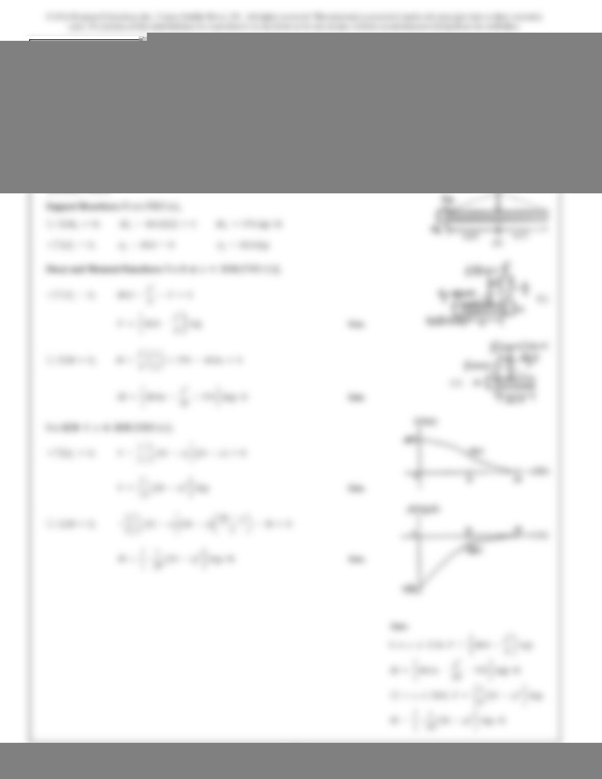
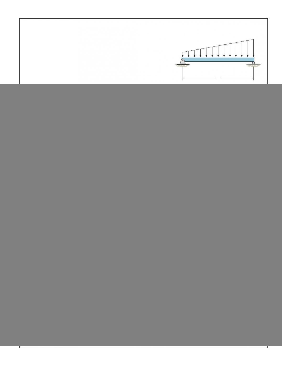
7–66.
Draw the shear and moment diagrams for the beam.
SOLUTION
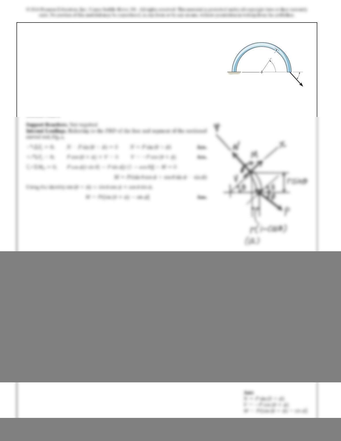
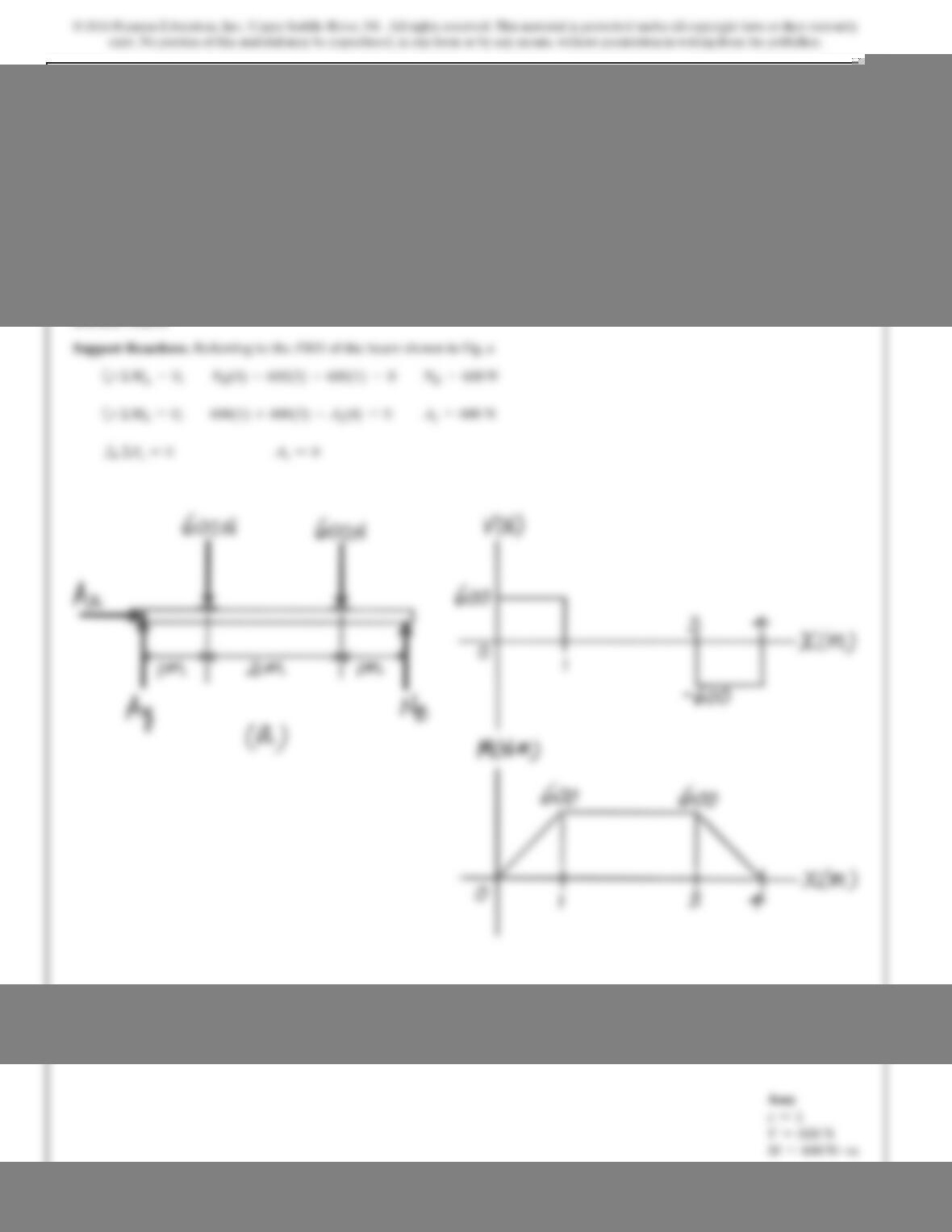
Support Reactions:
From FBD (a),
a
Shear and Moment Functions:
For [FBD (b)],
Ans.
The maximum moment occurs when then
a
Ans.
Thus,
Ans.=0.0940wL
2
M
max
=w
12L34L
2
10.5275L2–3L10.5275L2
2
–10.5275L2
3
4
M=w
12L14L
2
x–3Lx
2
–x
3
2
M+1
2aw
2Lxbxax
3b+wx
2ax
2b–wL
31x2=0+©M=0;
0=4L
2
–6Lx –3x
2
x=0.5275L
V=0,
V=w
12L14L
2
–6Lx –3x
2
2
wL
3–w
2x–1
2aw
2Lxbx–V=0+c©F
y
=0;
0…x…L
wL
4aL
3b+wL
2aL
2b–A
y
1L2=0A
y
=wL
3
+©M
B
=0;
w
L
w
––
2
AB
© 2016 Pearson Education, Inc., Upper Saddle River, NJ. All rights reserved. This material is protected under all copyright laws as they currently
exist. No portion of this material may be reproduced, in any form or by any means, without permission in writing from the publisher.
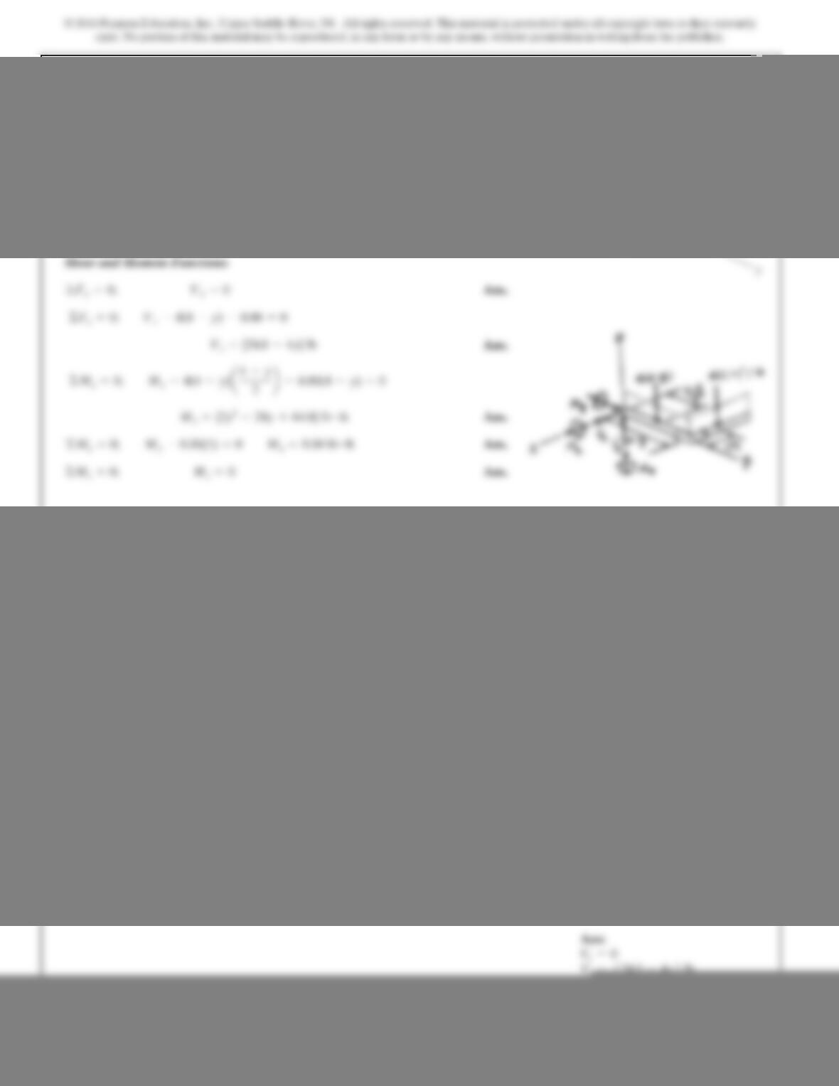
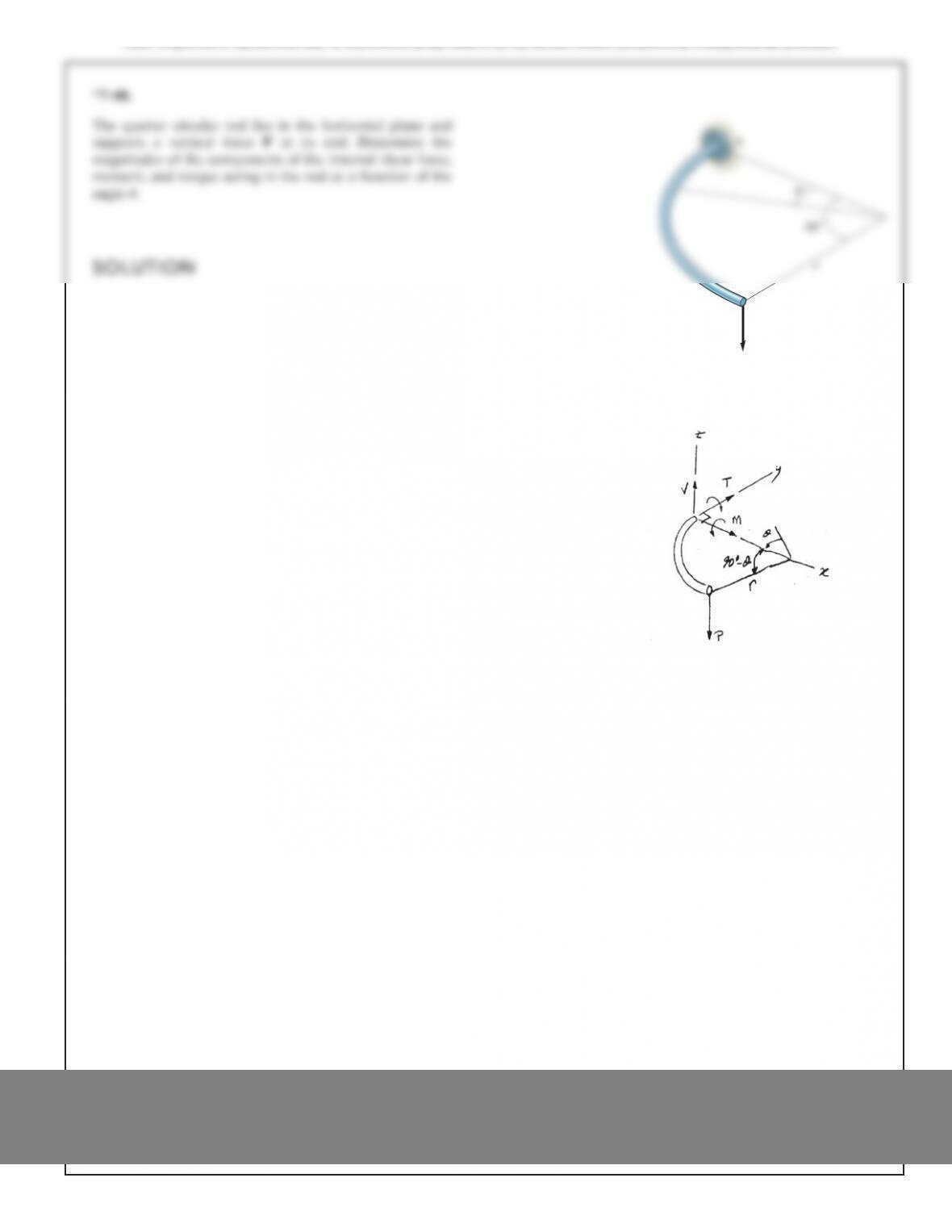
7–69.
Express t
h
e
i
nterna
l
s
h
ear an
d
moment components act
i
ng
in the rod as a function of y, where 0 …y…4 ft.
y
z
x
4ft2ft
4lb/ft
SOLUTION
SOLUTION
7–70.
Draw the shear and moment diagrams for the beam.
1 m1 m1
m1
m
800 N
600 N
A B
1200 N m
SOLUTION
7–71.
Draw the shear and moment diagrams for the beam.
1 m 2 m 1 m
600 N 600 N
AB
689
*7–72.
Draw the shear and moment diagrams for the beam. The
support at Aoffers no resistance to vertical load.
SOLUTION
L
A B
w
0
690
7–73.
Draw the shear and moment diagrams for the simply-
supported beam.
SOLUTION
w
0
2w
0
L/2L/2
AB