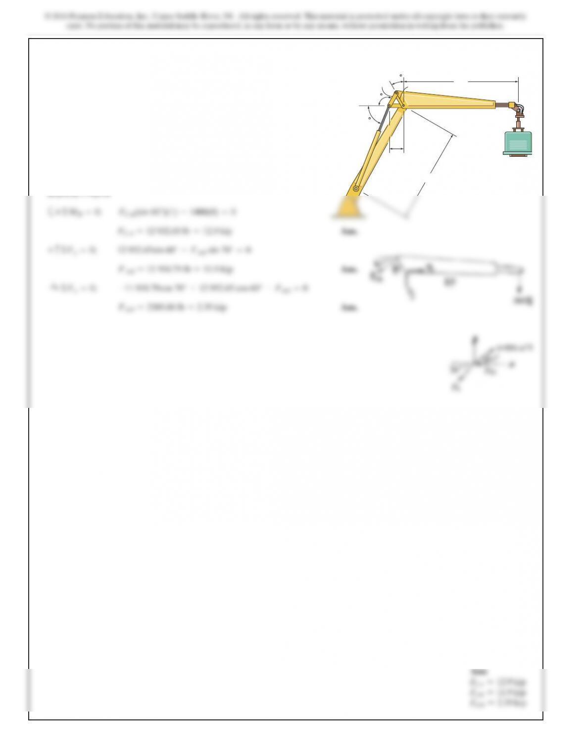
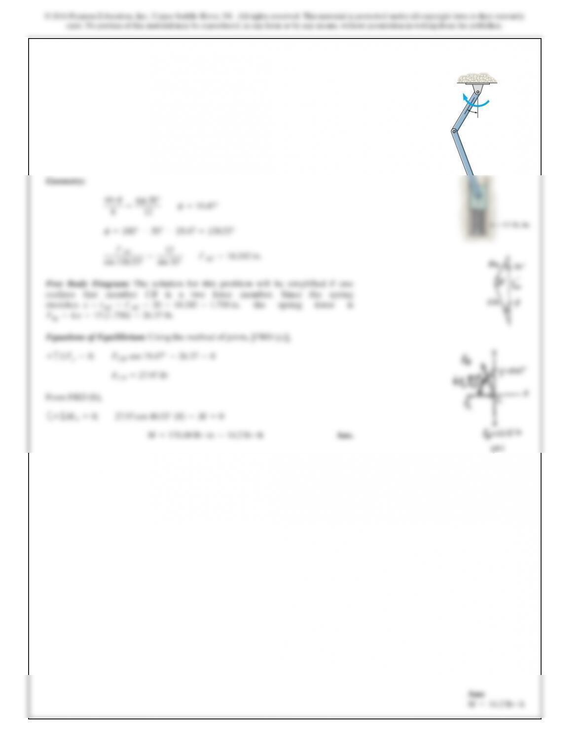
*6–104.
The hydraulic crane is used to lift the 1400-lb load.
Determine the force in the hydraulic cylinder AB and the
force in links AC and AD when the load is held in the
position shown.
8 ft
30
120
70
1 ft
1 ft
1 ft
B
AD
C
7 ft
SOLUTION
SOLUTION
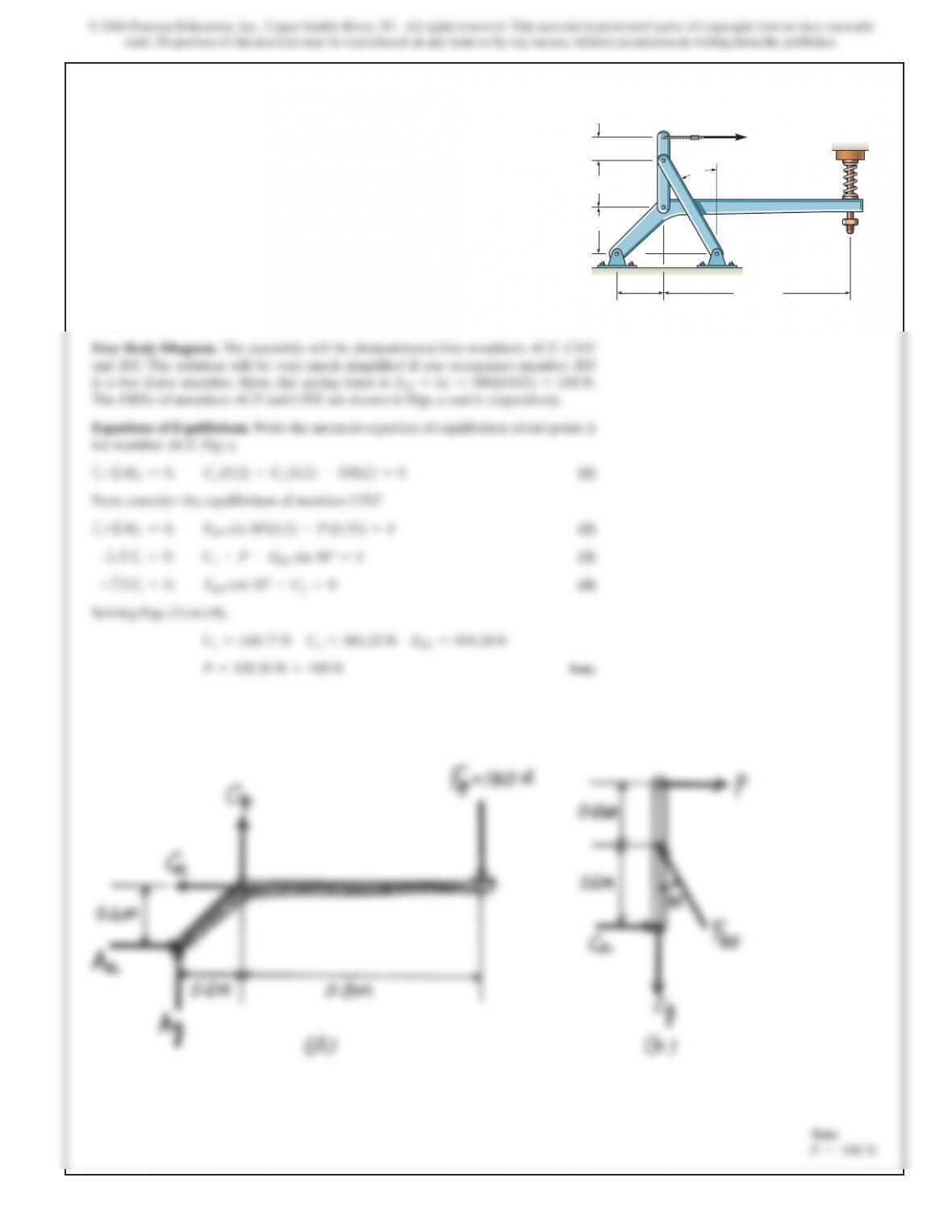
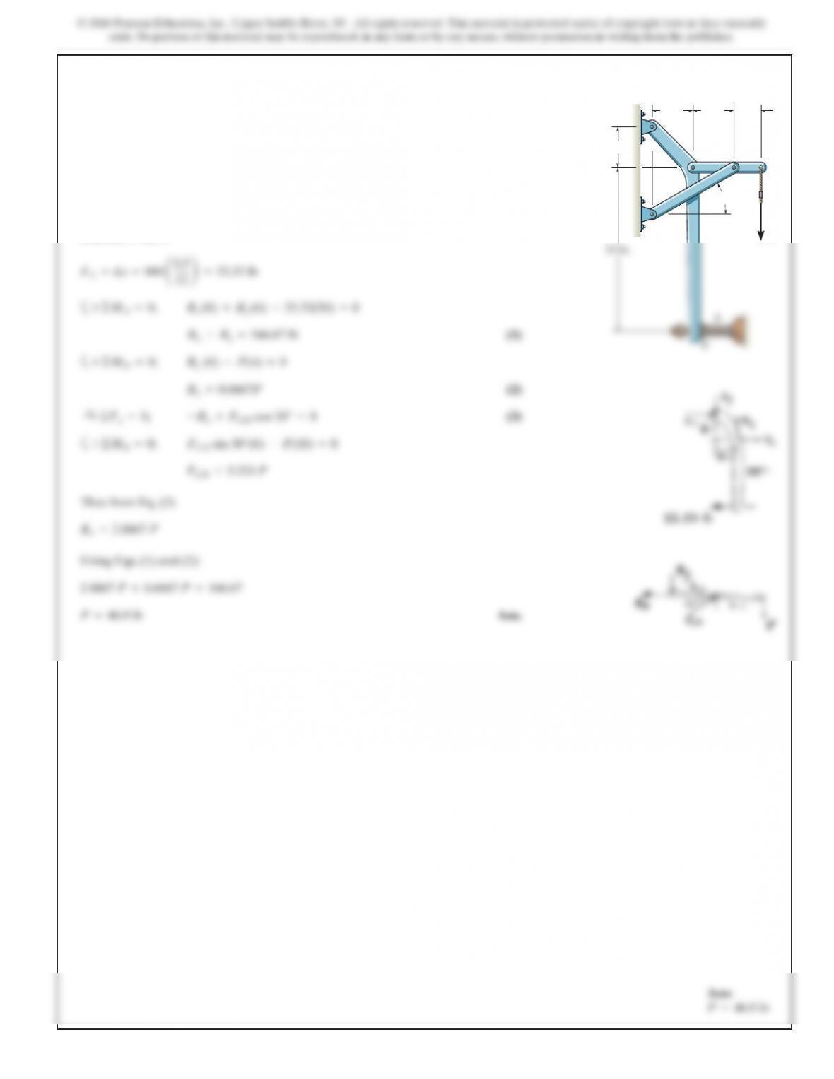
6–105.
Determine force P on the cable if the spring is compressed
0.025 m when the mechanism is in the position shown. The
spring has a stiffness of k = 6 kN
>
m.
P
150 mm
200 mm
200 mm
200 mm 800 mm
A
C
D
E
B
F
30
k
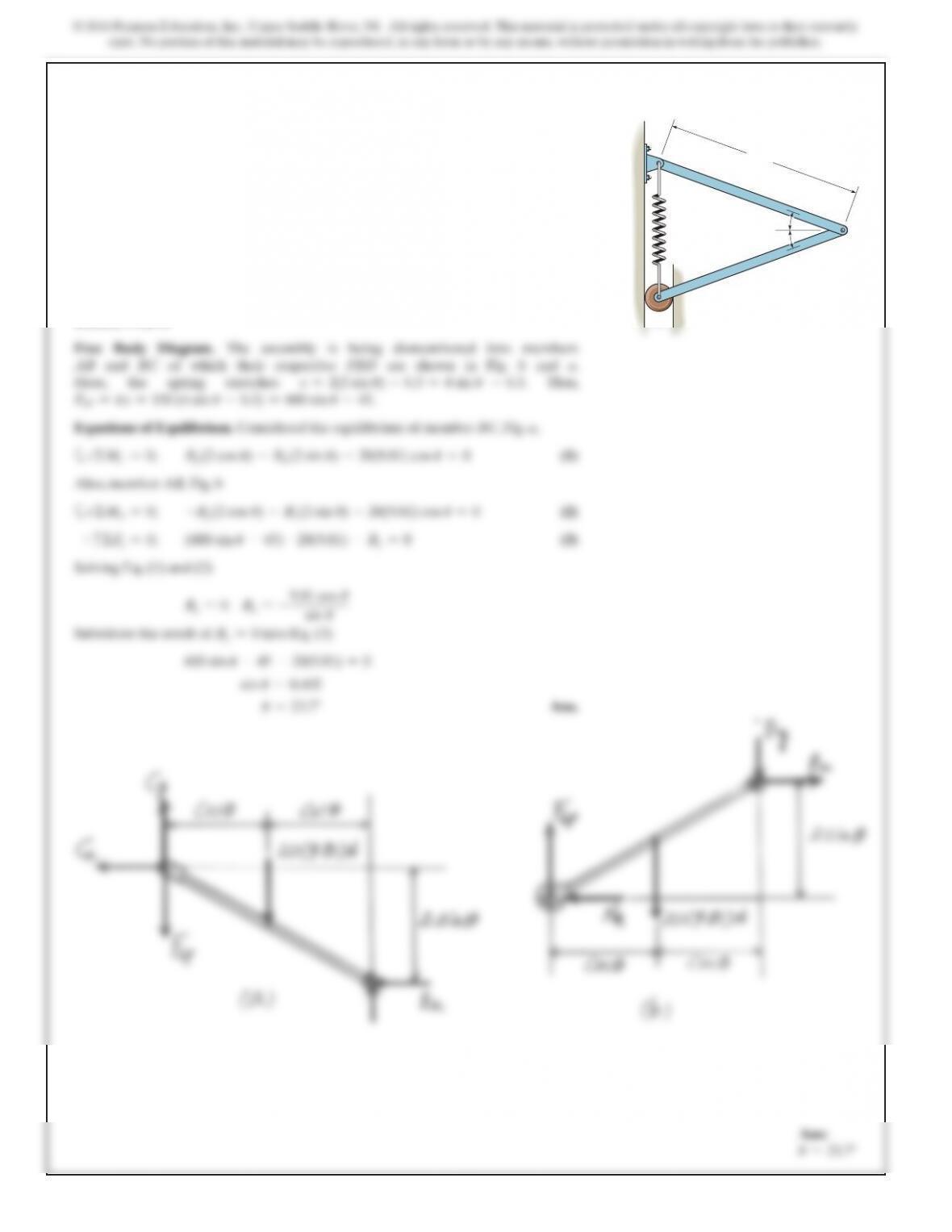
6–106.
If and the spring has an unstretched length of 1 ft,
determine the force Frequired for equilibrium.
SOLUTION
Equations of Equilibrium: First, we will analyze the equilibrium of joint B. From the
free-body diagram in Fig. a,
From the free-body diagram in Fig. b, using the result , and
analyzing the equilibrium of joint C, we have
Ans.F =66.14 lb =66.1 lb
2(50 cos 48.59°) –F=0©F
x=0;
:
+
F
CD sin 48.59° –50 sin 48.59° =0
F
CD =50 lb+c©F
y=0;
F
BC =F¿ = 50 lb
F¿ =50 lb
2F¿ sin 48.59° –75 =0+c©F
y=0;
F
AB =F
BC =F¿
F
AB cos 48.59° –F
BC cos 48.59° =0©F
x=0;
:
+
d
=0.75 ft
d
d
AC
B
1 ft
1 ft
1 ft
1 ft
k 150 lb/ft
FF
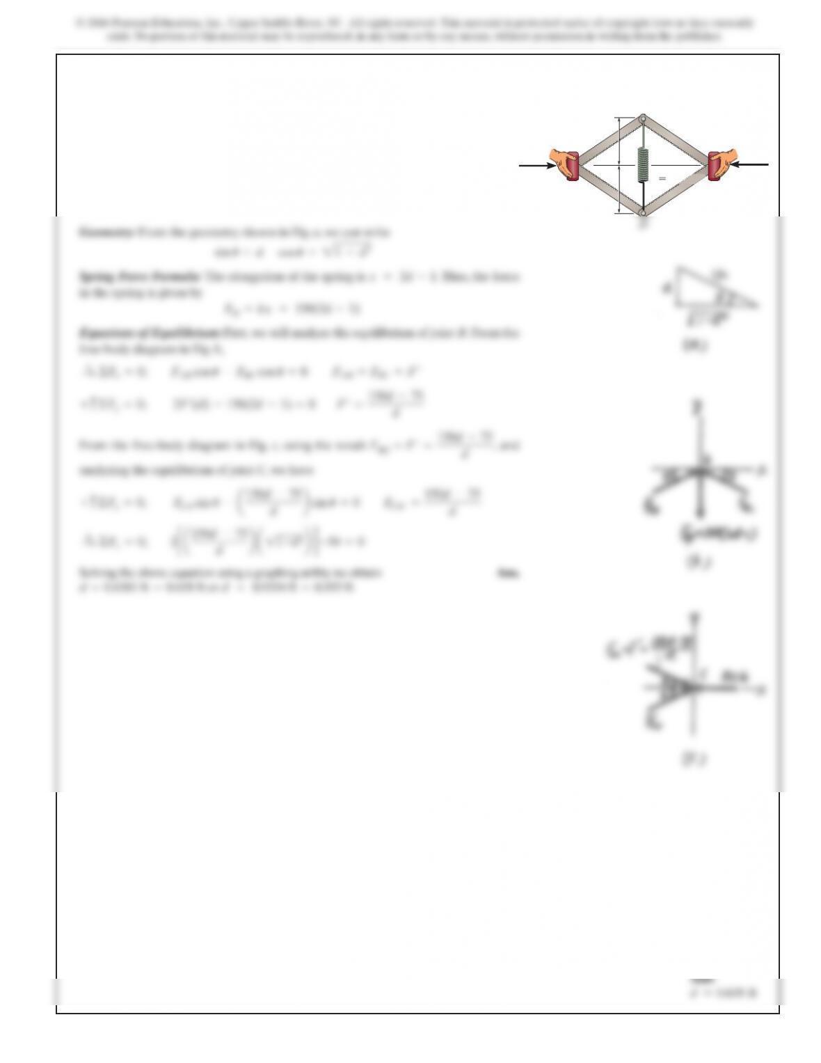
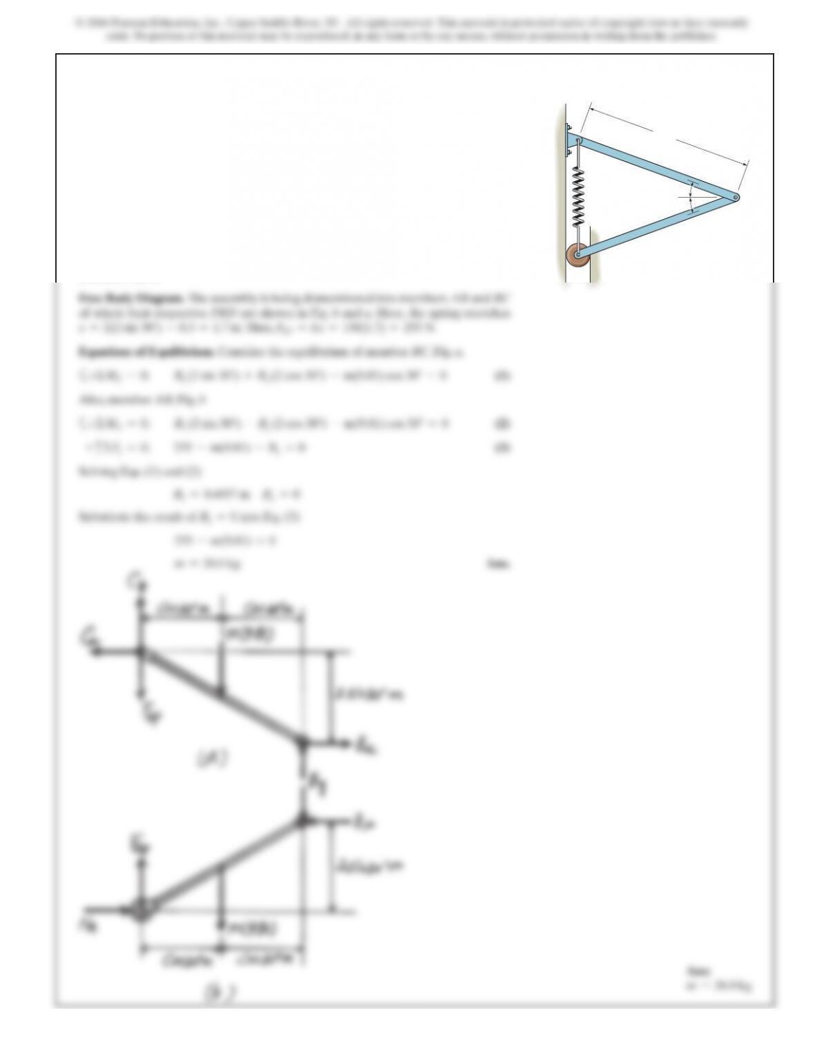
6–107.
If a force of is applied to the pads at Aand C,
determine the smallest dimension drequired for equilibrium if
the spring has an unstretched length of 1 ft.
SOLUTION
Spring Force Formula: The elongation of the spring is . Thus, the force
in the spring is given by
Equations of Equilibrium:First, we will analyze the equilibrium of joint B. From the
free-body diagram in Fig. b,
From the free-body diagram in Fig. c, using the result FBC =, and
analyzing the equilibrium of joint C, we have
Solving the above equation using a graphing utility, we obtain Ans.
or d = 0.9334 ft =0.933 ft0.6381 ft =0.638 ftd=
2ca150d–75
dba11–d2bd–50 =0©F
x=0;
:
+
F
CD =150d–75
d
F
CD sin u–a150d–75
db sin u=0+c©F
y=0;
F¿ = 150d–75
d
F¿ = 150d–75
d
2F¿(d)–150(2d–1) =0+c©F
y=0;
F
AB cos u–F
BC cos u=0
F
AB =F
BC =F¿©F
x=0;
:
+
F
sp =kx = 150(2d–1)
x = 2d–1
F
=50 lb
d
d
AC
B
1 ft
1 ft
1 ft
1 ft
k 150 lb/ft
FF
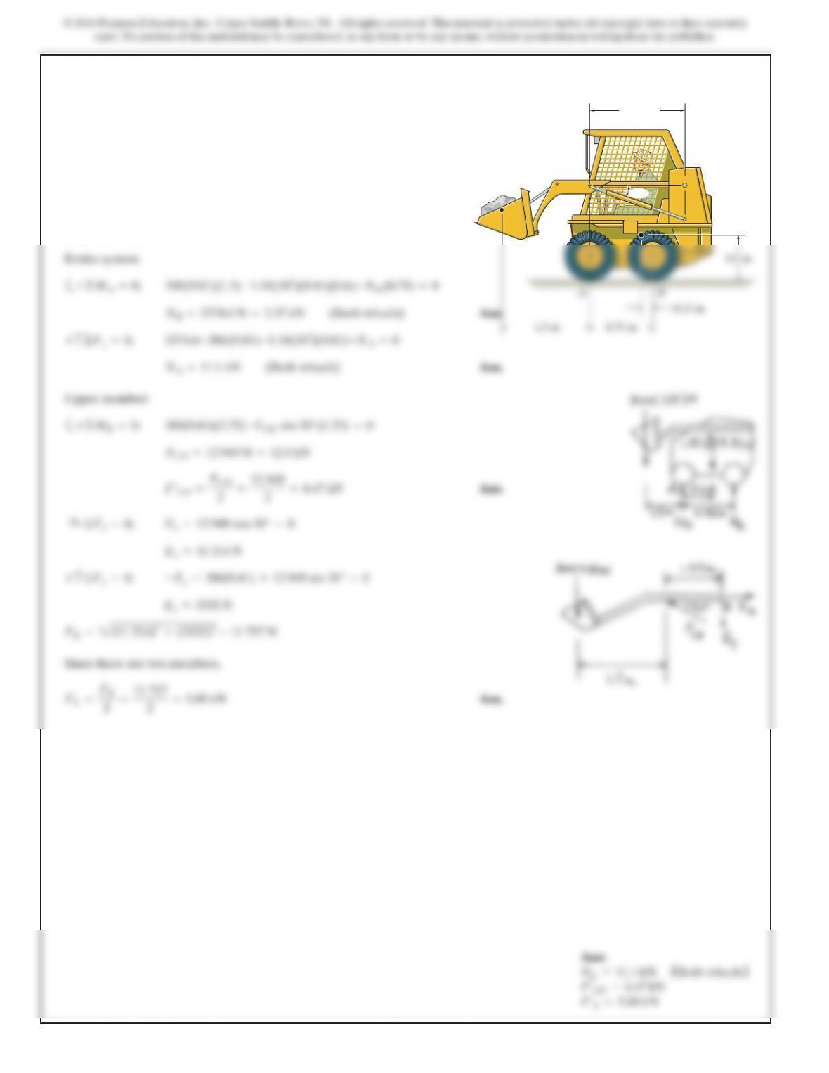
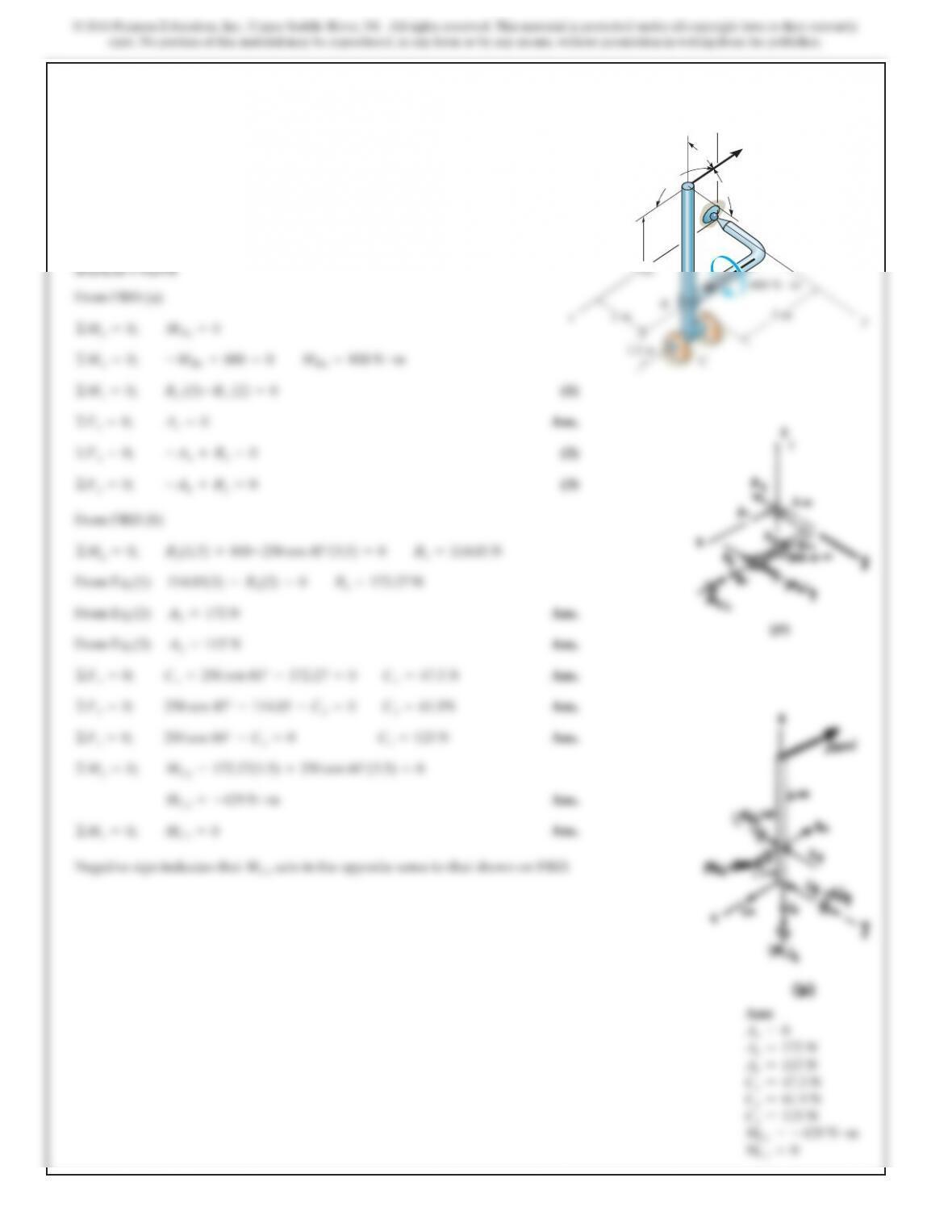
*6–108.
Theskid steer loader hasamass of 1.18 Mg,and in the
position shown the center of mass is at If there is a300-kg
stone in the bucket, with center of mass at determine the
reactions of each pair of wheels Aand Bon the ground and
the force in the hydraulic cylinder CD and at the pin E.There
isasimilar linkage on each side of the loader.
G2,
G1.
1.25 m
C
D
G
1
G
2
E
30
SOLUTION
6–109.
Determine the force Pon the cable if the spring is
compressed 0.5 in. when the mechanism is in the position
shown. The spring has a stiffness of k=800 lb>ft.
SOLUTION
a
(1)
a
(2)
(3)
a
Thus from Eq. (3)
Using Eqs. (1) and (2):
Ans.P=46.9 lb
2.8867 P+0.6667 P=166.67
Bx=2.8867 P
FCD =3.333 P
+©MB=0; FCD sin 30°(6) –P(10) =0
:
+©Fx=0; –Bx+FCD cos 30° =0
By=0.6667P
+©MD=0; By(6) –P(4) =0
Bx+By=166.67 lb
+©MA=0;
Bx(6) +By(6) –33.33(30) =0
FE=ks =800 a0.5
12 b=33.33 lb
P
6 in.
24 in.
6 in. 6in. 4 in.
A
C
D
E
B
30
k
SOLUTION
6–110.
The spring has an unstretched length of 0.3 m. Determine
the angle
u
for equilibrium if the uniform bars each have a
mass of 20 kg.
2 m
k 150 N/m
A
B
C
u
u
SOLUTION
6–111.
The spring has an unstretched length of 0.3 m. Determine
the mass m of each uniform bar if each angle
u=30°
for
equilibrium. 2 m
k 150 N/m
A
B
C
u
u
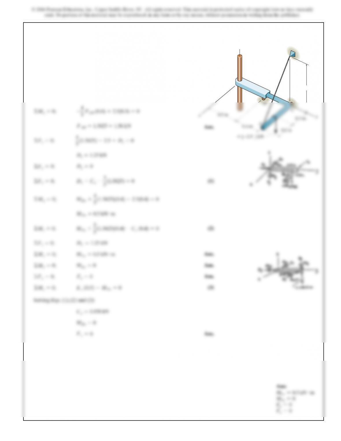
*6–112.
The piston Cmoves vertically between the two smooth
walls. If the spring has a stiffness of and is
unstretched when determine the couple Mthat
must be applied to AB to hold the mechanism in
equilibrium when u=30°.
u=0°,
k=15 lb
>
in.,
SOLUTION
A
M
u
B
8 in.
12 in.
6–113.
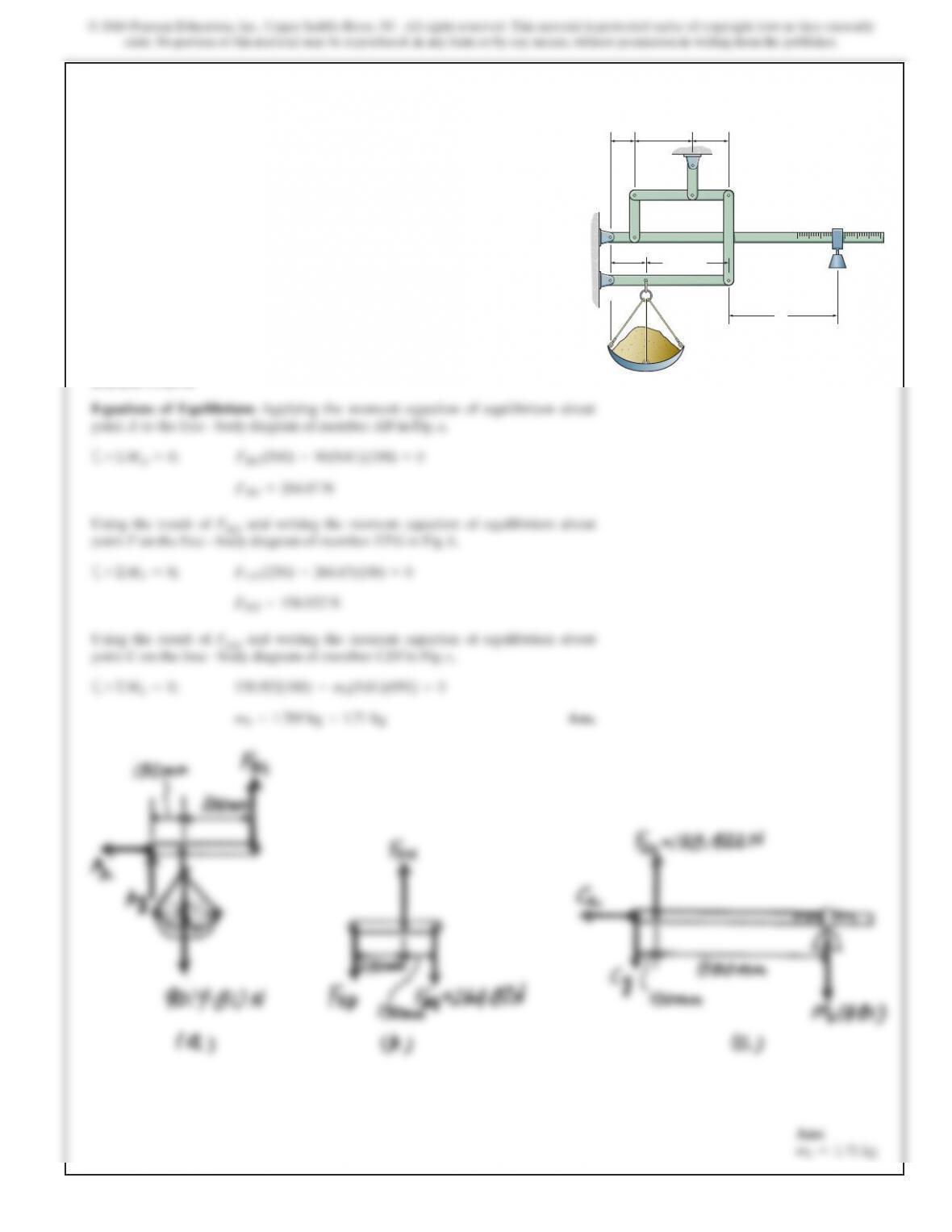
The platform scale consists of a combination of third and first
class levers so that the load on one lever becomes the effort
that moves the next lever.Through this arrangement, a small
weight can balance a massive object. If ,
determine the required mass of the counterweight Srequired
to balance a 90-kg load, L.
x=450 mm
SOLUTION
Using the result of FBG and writing the moment equation of equilibrium about
point Fon the free – body diagram of member EFG in Fig. b,
a
Using the result of FED and writing the moment equation of equilibrium about
point Con the free – body diagram of member CDI in Fig. c,
a
Ans.mS=1.705 kg =1.71 kg
+©MC=0; 158.922(100) –mS(9.81)(950) =0
FED =158.922 N
+©MF=0; FED (250) –264.87(150) =0
FBG =264.87 N
350mm
150 mm
150 mm100 mm
250 mm
B
A
CD
EF
H
G
x
L
S
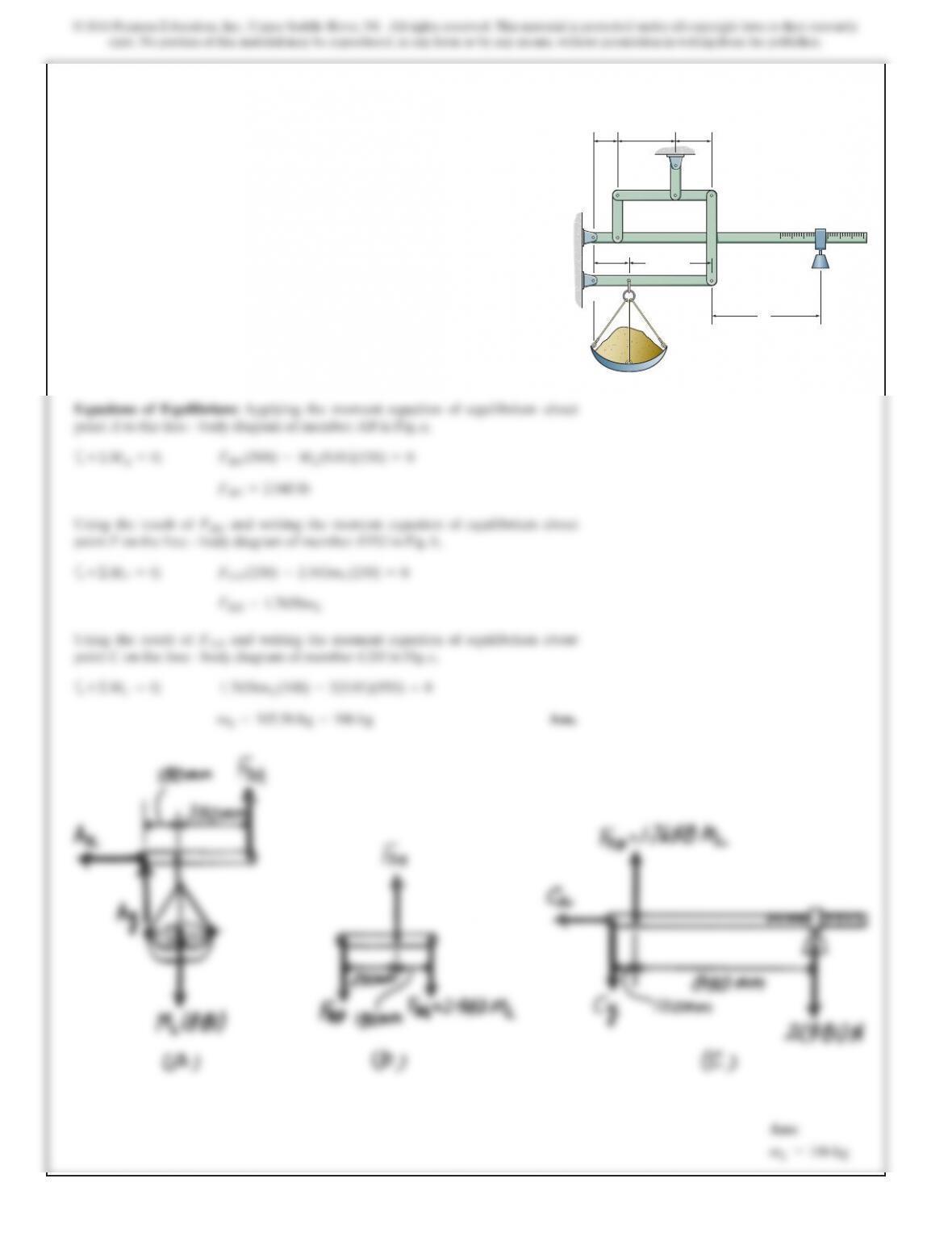
6–114.
SOLUTION
Using the result of and writing the moment equation of equilibrium about
point Fon the free – body diagram of member EFG in Fig. b,
a
Using the result of and writing the moment equation of equilibrium about
point Con the free – body diagram of member CDI in Fig. c,
a
Ans.mL=105.56 kg =106 kg
+©MC=0; 1.7658mL(100) –2(9.81)(950) =0
FED
FED =1.7658mL
+©MF=0; FED (250) –2.943mL(150) =0
FBG
FBG =2.943 lb
The platform scale consists of a combination of third and
first class levers so that the load on one lever becomes the
effort that moves the next lever.Through this arrangement,
a small weight can balance a massive object. If
and, the mass of the counterweight Sis 2 kg, determine the
mass of the load Lrequired to maintain the balance.
x=450 mm
350mm
150 mm
150 mm100 mm
250 mm
B
A
CD
EF
H
G
x
L
S
6–115.
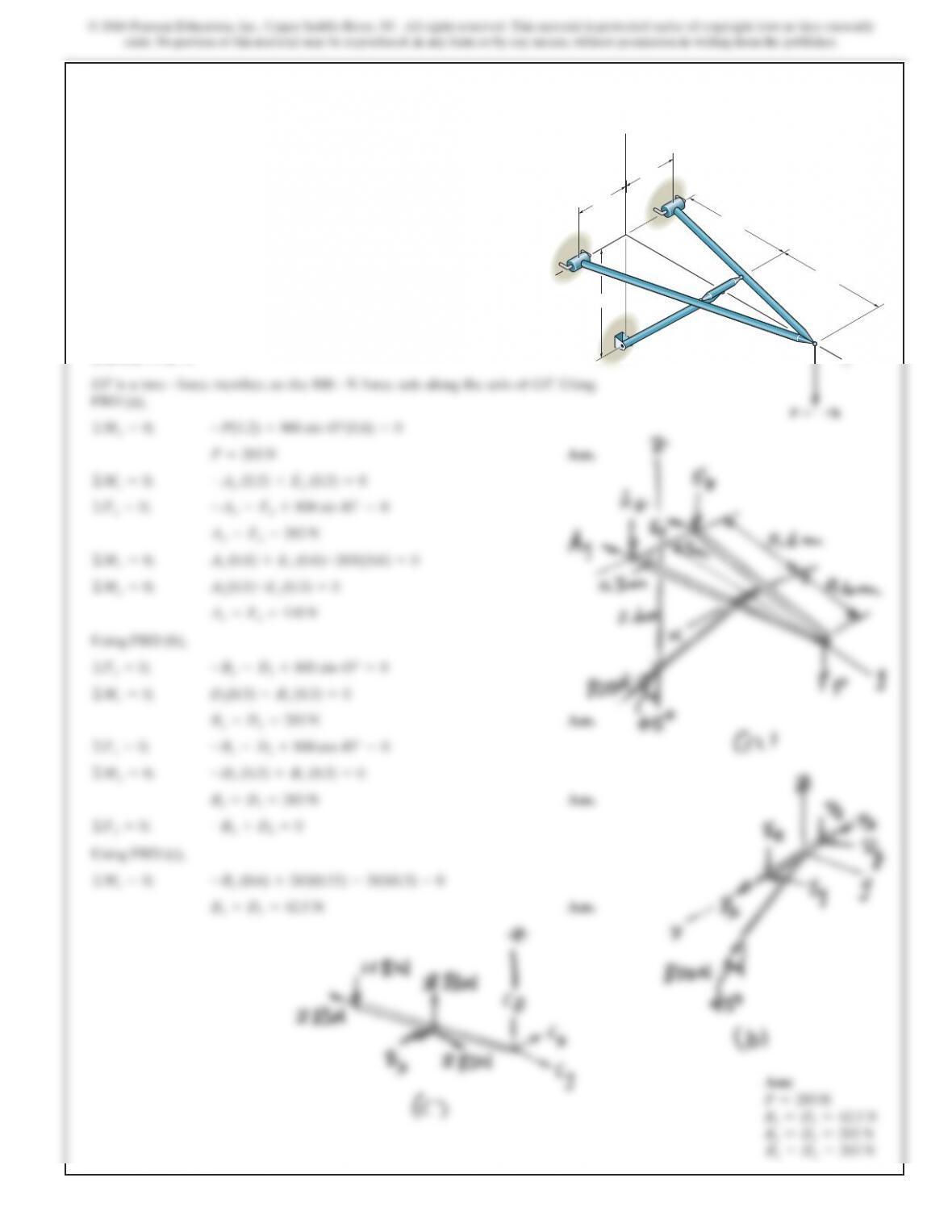
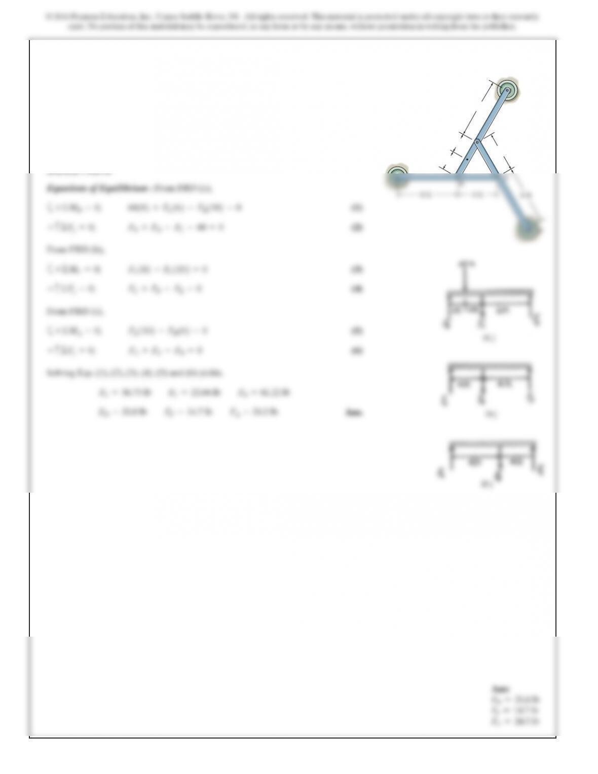
The four-member “A” frame is supported at Aand Eby
smooth collars and at Gby a pin. All the other joints are
ball-and-sockets. If the pin at Gwill fail when the resultant
force there is 800 N, determine the largest vertical force P
that can be supported by the frame. Also, what are the x, y, z
force components which member BD exerts on members
EDC and ABC?The collars at Aand Eand the pin at G
only exert force components on the frame.
x
y
C
D
BF
G
E
A
z
300 mm
300 mm
600 mm
600 mm
600 mm
SOLUTION
*6–116.
(1)
Ans.
(2)
(3)
From FBD (b)
From Eq.(1)
From Eq.(2) Ans.
From Eq.(3) Ans.
Ans.
Ans.
Ans.
Ans.
Ans.
Negative sign indicates that acts in the opposite sense to that shown on FBD.MCy
©Mz=0; MCz =0
MCy =-429 N #m
©My=0; MCy –172.27(1.5) +250 cos 60°(5.5) =0
©Fz=0; 250 cos 60° –Cz=0Cz=125 N
©Fy=0; 250 cos 45° –114.85 –Cy=0Cy=61.9N
©Fx=0; Cx+250 cos 60° –172.27 =0Cx=47.3 N
Ay=115 N
Ax=172 N
114.85(3) –Bx(2) =0Bx=172.27 N
©Mg=0; By(1.5) +800–250 cos 45°(5.5) =0By=114.85 N
©Fy=0; –Ay+By=0
©Fx=0; –Ax+Bx=0
©Fz=0; Az=0
©Mz=0; By(3)–Bx(2) =0
©Mx=0; –MBx +800 =0MBx =800 N #m
The structure is subjected to the loadings shown. Member
AB is supported by a ball-and-socket at Aand smooth
collar at B. Member CD is supported by a pin at C.
Determine the x, y, zcomponents of reaction at Aand C.
1.5 m
A
250 N
D
45
60
60
z
C
Ans:
A
z
=0
Ax=172 N
A
y
=115 N
Cx=47.3 N
C
y
=61.9 N
C
z
=125 N
M
Cy
=–429 N #m
MC
z
=0
6–117.
SOLUTION
©M
y
=0; –4
5 F
AB
(0.6) +2.5(0.3) =0
The structure is subjected to the loading shown. Member AD
is supported by a cable AB and roller at C and fits through
a smooth circular hole at D. Member ED is supported by a
roller at Dand a pole that fits in a smooth snug circular hole
at E. Determine the x, y, z components of reaction at E and
the tension in cable AB.
z
C
A
D
B
E
0.3 m y
0.5 m
x
0.8 m
6–118.
(2)
From FBD (b),
a(3)
(4)
From FBD (c),
a(5)
(6)
Solving Eqs. (1), (2), (3), (4), (5) and (6) yields,
Ans.F
D
=20.8 lb
F
F
=14.7 lb
F
A
=24.5 lb
F
E
=36.73 lb
F
C
=22.04 lb
F
B
=61.22 lb
F
A
+F
E
–F
B
=0+c©F
y
=0;
F
E
1102–F
B
162=0+ ©M
A
=0;
F
C
+F
F
–F
E
=0+c©F
y
=0;
F
E
162–F
C
1102=0+ ©M
F
=0;
F
+F
–F
–60 =0+c©F
=0;
The three pin-connected members shown in the top view
support a downward force of 60 lb at G.If only vertical forces
are supported at the connections B, C, E and pad supports A,
D, F, determine the reactions at each pad.
D
G
C
6 ft
2 ft
2 ft
4 ft