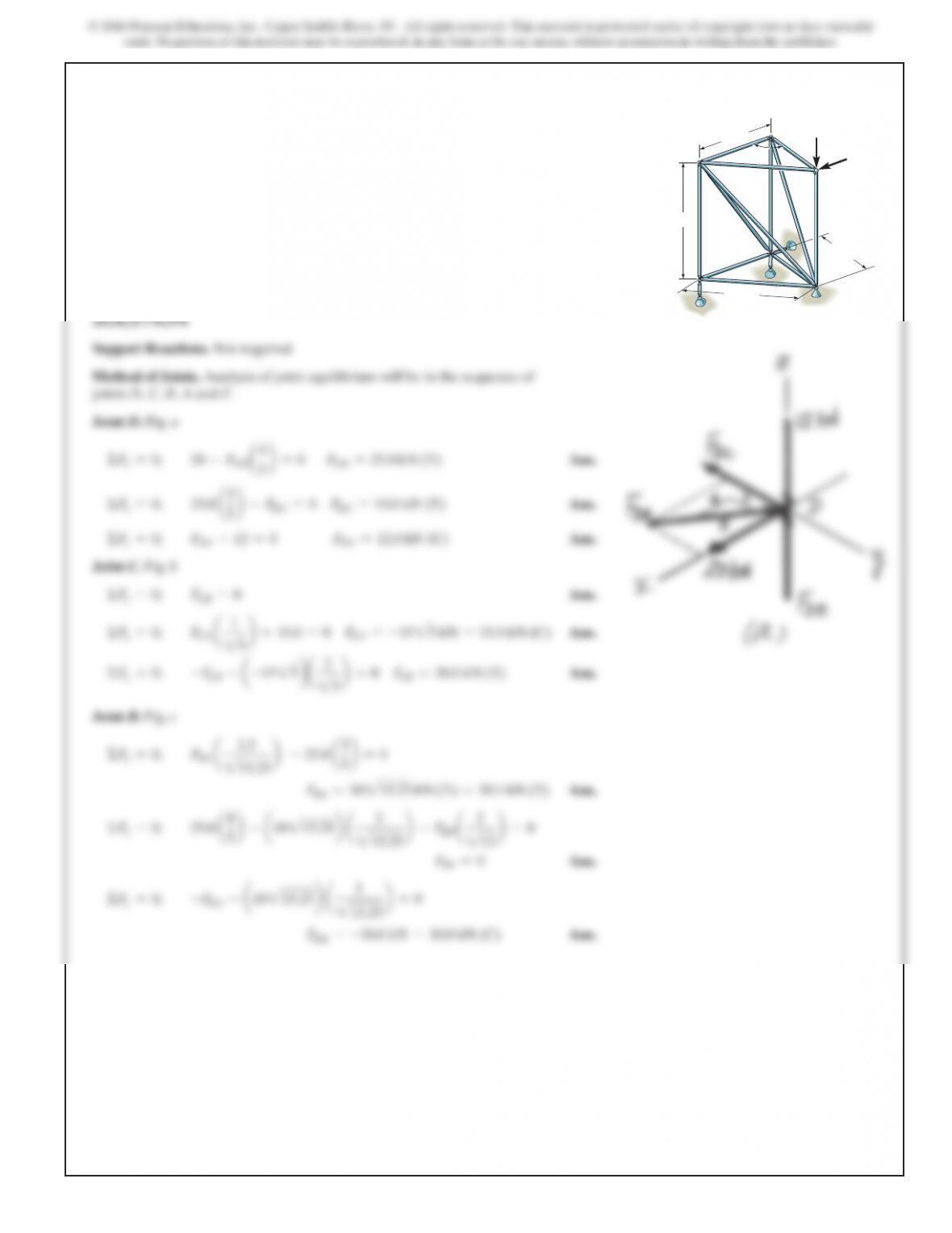
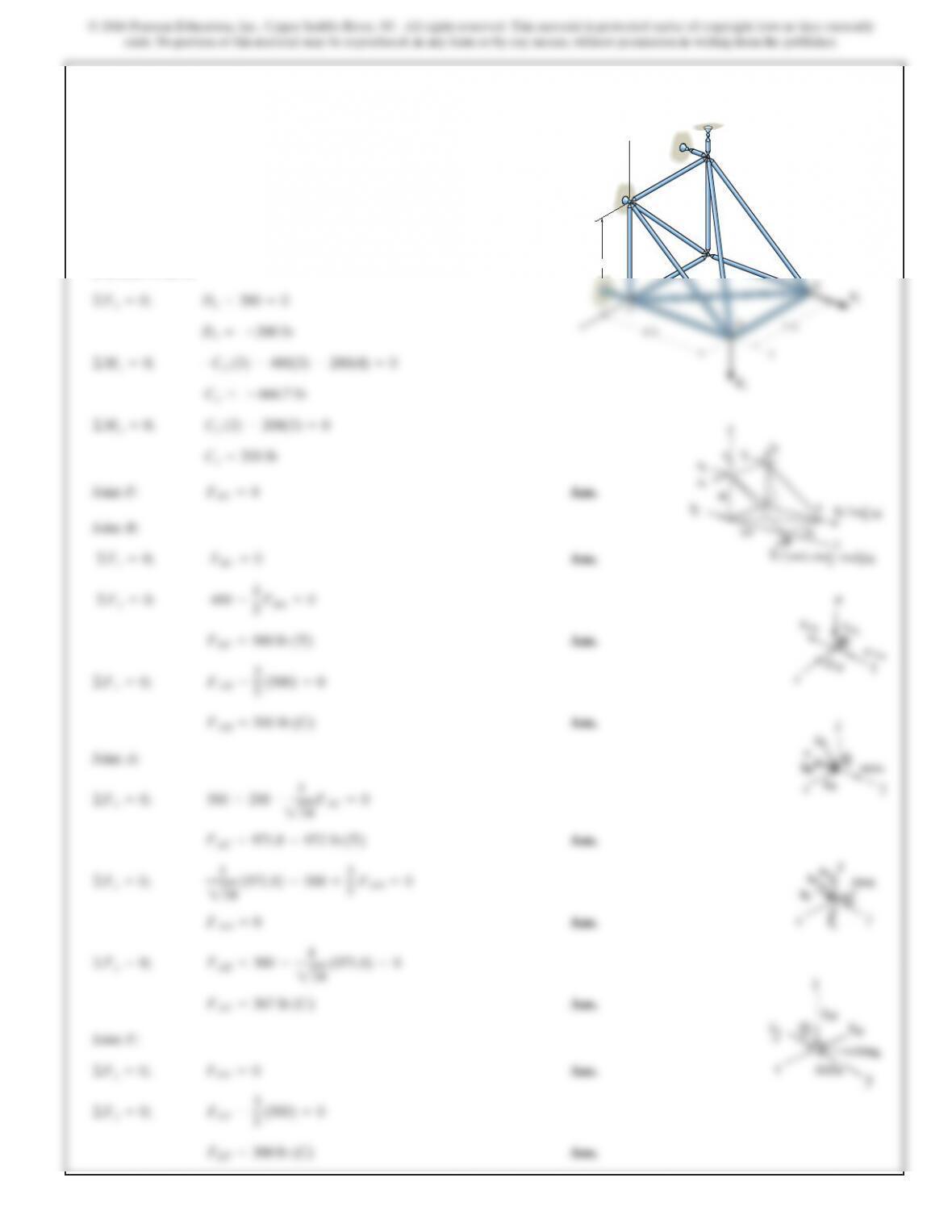
6–53.
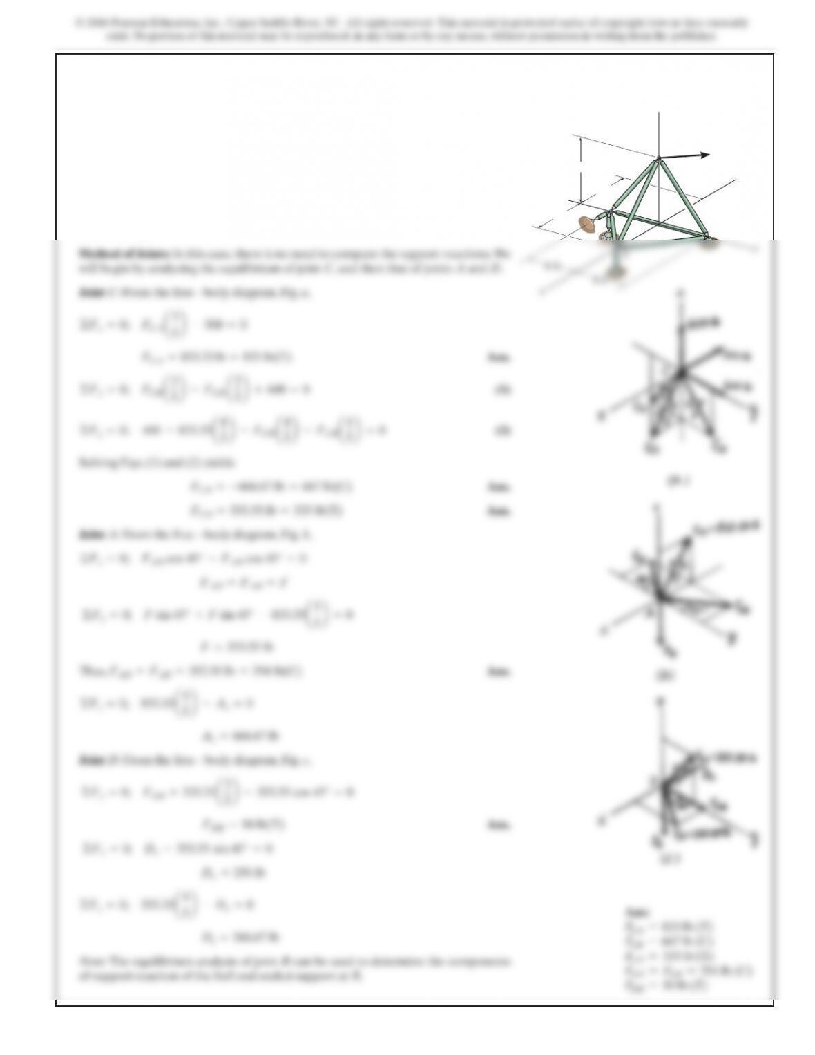
The space truss supports a force
. Determine the force in each member, and state if
the members are in tension or compression.
400k
6
lb
F=5–500i+600j+
B
C
D
y
z
F
8ft
6ft
6ft
SOLUTION
6–54.
SOLUTION
Ans.
(1)
(2)
Solving Eqs. (1) and (2) yields
Ans.
Ans.
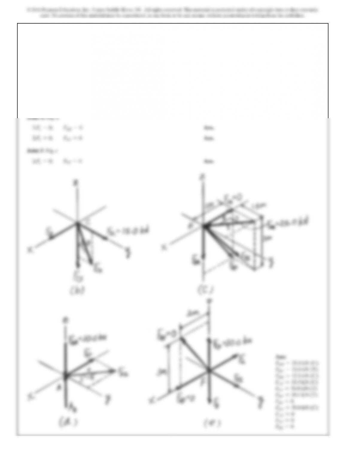
Joint A:From the free – body diagram, Fig. b,
Thus, Ans.
Joint D:From the free – body diagram, Fig. c,
Ans.
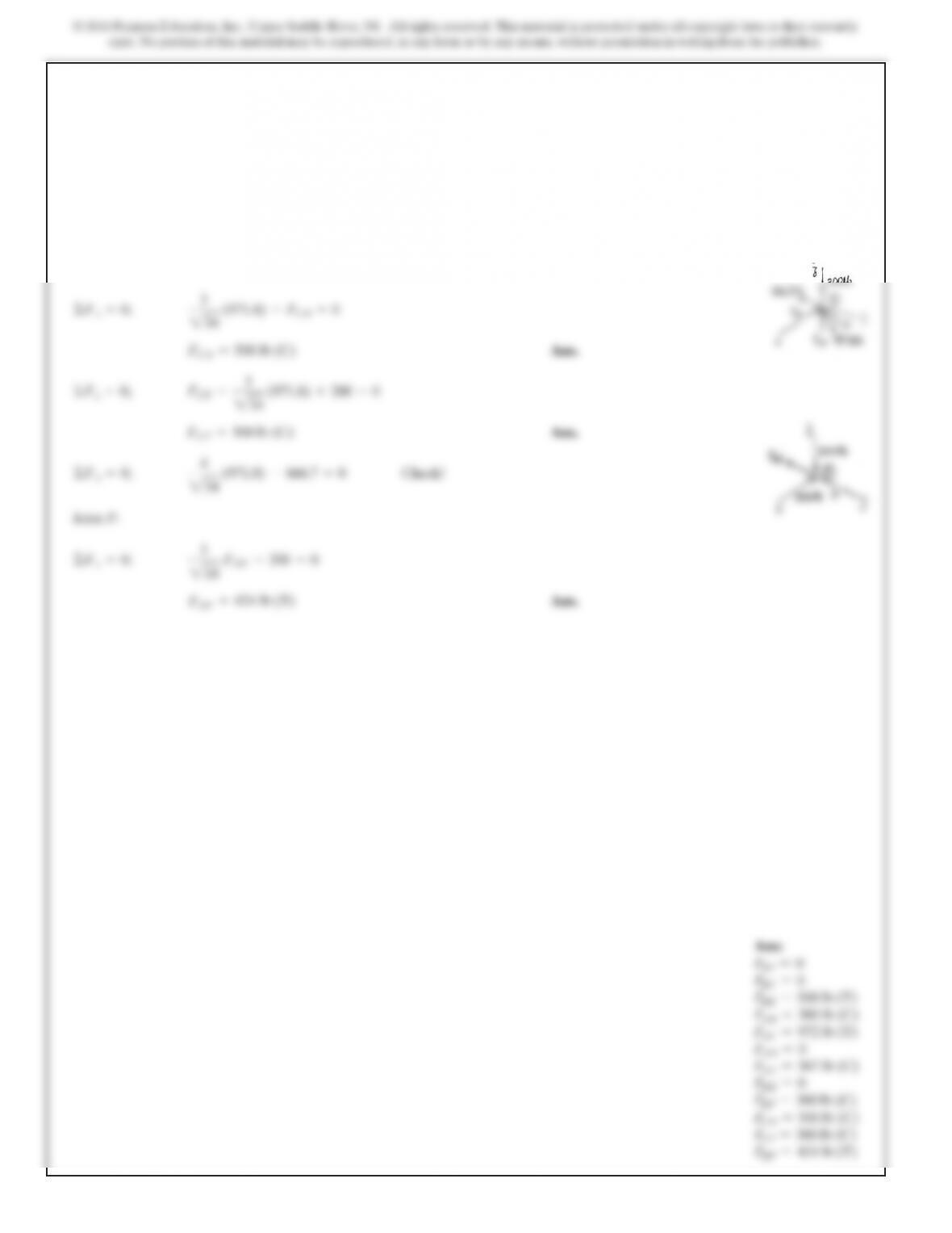
Dx =300 lb
©Fx=0; 424.26 sin 45° –Dx=0
FDB =543.75 lb =544 lb(C)
©Fy=0; 406.25a3
5b+406.25 cos 45° –FDB =0
Az=800 lb
©Fz=0; Az–1000a4
5b=0
FAB =FAD =424.26 lb =424 lb (T)
F=424.26 lb
©Fx=0; 1000a3
5b–Fsin 45° –Fsin 45° =0
FAB =FAD =F
©Fy=0; FAB cos 45° –FAD cos 45° =0
FCB =-343.75 lb =344 lb(C)
FCD =406.25 lb =406 lb(T)
©Fz=0; –FCB a4
5b–FCD a4
5b–(–1000)a4
5b–750 =0
©Fy=0; FCB a3
5b–FCD a3
5b+450 =0
FCA =-1000 lb =1000 lb(C)
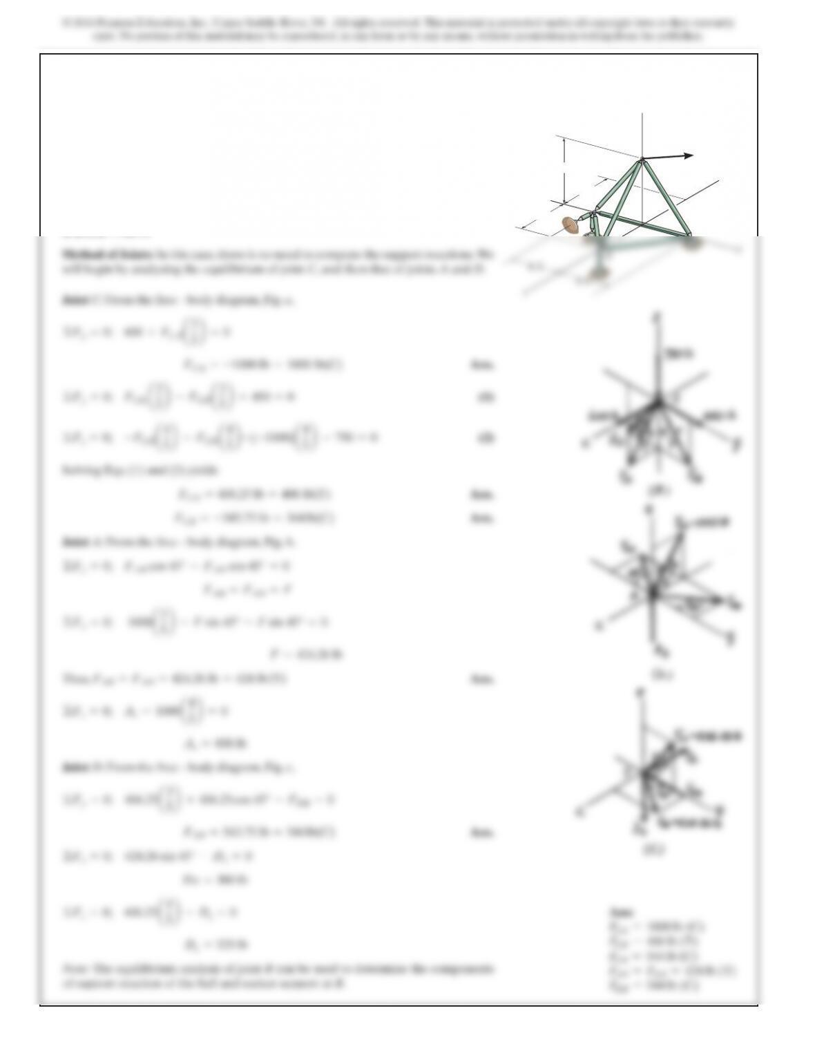
The space truss supports a force
. Determine the force in each member, and state if
the members are in tension or compression.
750k
6
lb
F=5600i+450j–
B
C
D
y
z
F
8ft
6ft
6ft
543
SOLUTION
6–55.
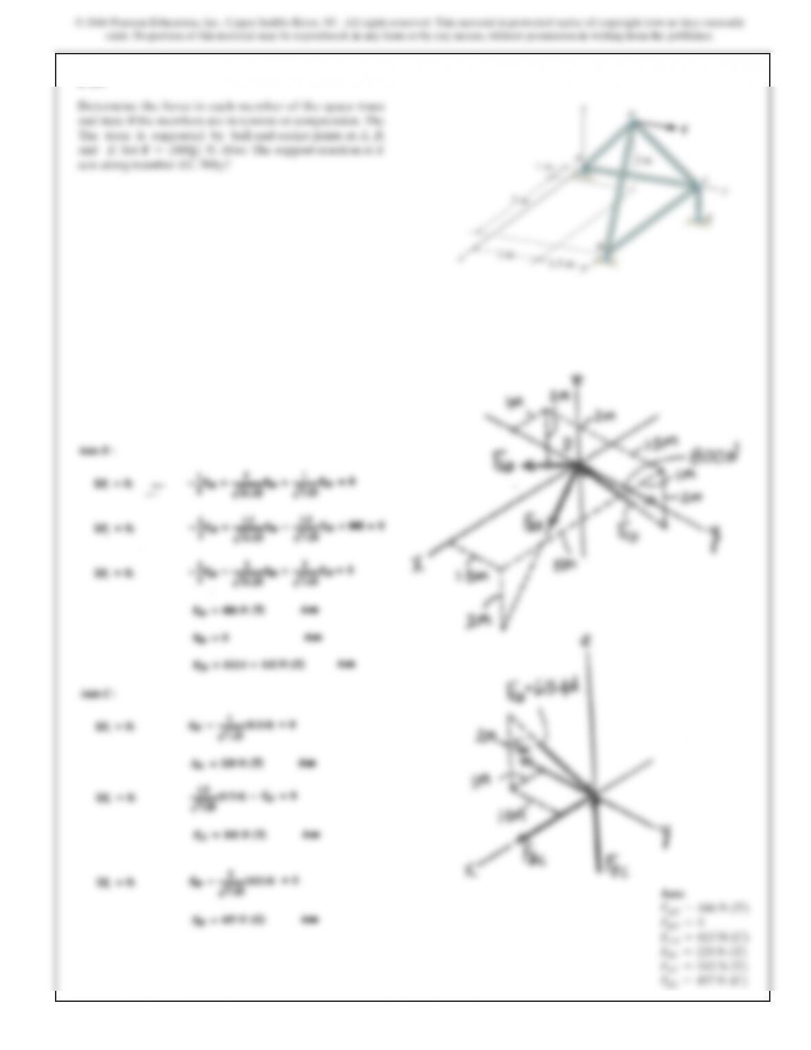
Determine the force in members EF, AF, and DF of the
space truss and state if the members are in tension or
compression. The truss is supported by short links at A, B,
D, and E.
z
3 m
3 m
4 kN
2 kN
3 kN
3 m
F
E
D
B
C
545
547
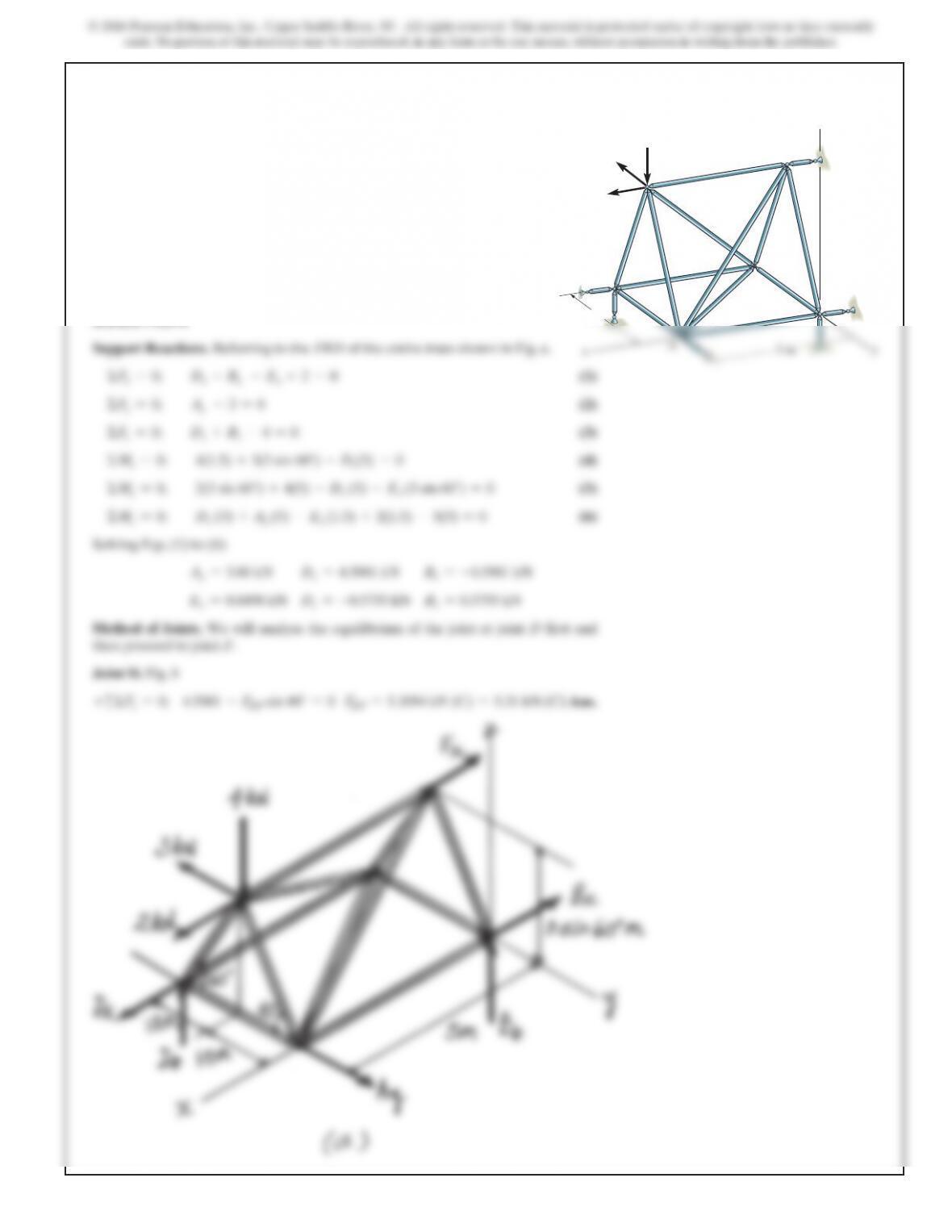
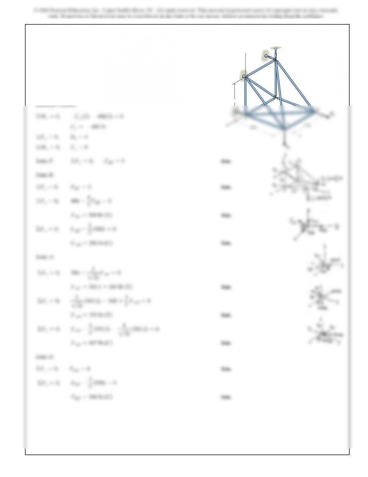
6–57.
The space truss is supported by a ball-and-socket joint at D
and
short links at Cand E. Determine the force in each
member
and state if the members are in tension or
compression.
Take and F
2
=5400j6lb.F
1
=5–500k6lb
J
oint F:Ans.
J
oint B:
Ans.
Ans.
Ans.
J
oint A:
Ans.
Ans.
Ans.
J
oint E:
Ans.
Ans.F
EF
=300 lb (C)
©F
x
=0; F
EF
–3
5(500) =0
©F
z
=0; F
DE
=0
F
AE
=667 lb (C)
©F
y
=0; F
AE
–4
5(333.3) –4
234 (583.1) =0
F
AD
=333 lb (T)
©F
z
=0; 3
234 (583.1) –500 +3
5F
AD
=0
F
AC
=583.1 =583 lb (T)
©F
x
=0; 300 –3
234 F
AC
=0
F
AB
=300 lb (C)
©F
x
=0; F
AB
–3
5(500) =0
F
BE
=500 lb (T)
©F
y
=0; 400 –4
5F
BE
=0
©F
z
=0; F
BC
=0
©F
y
=0;
F
BF
=0
3ft
z
C
D
F
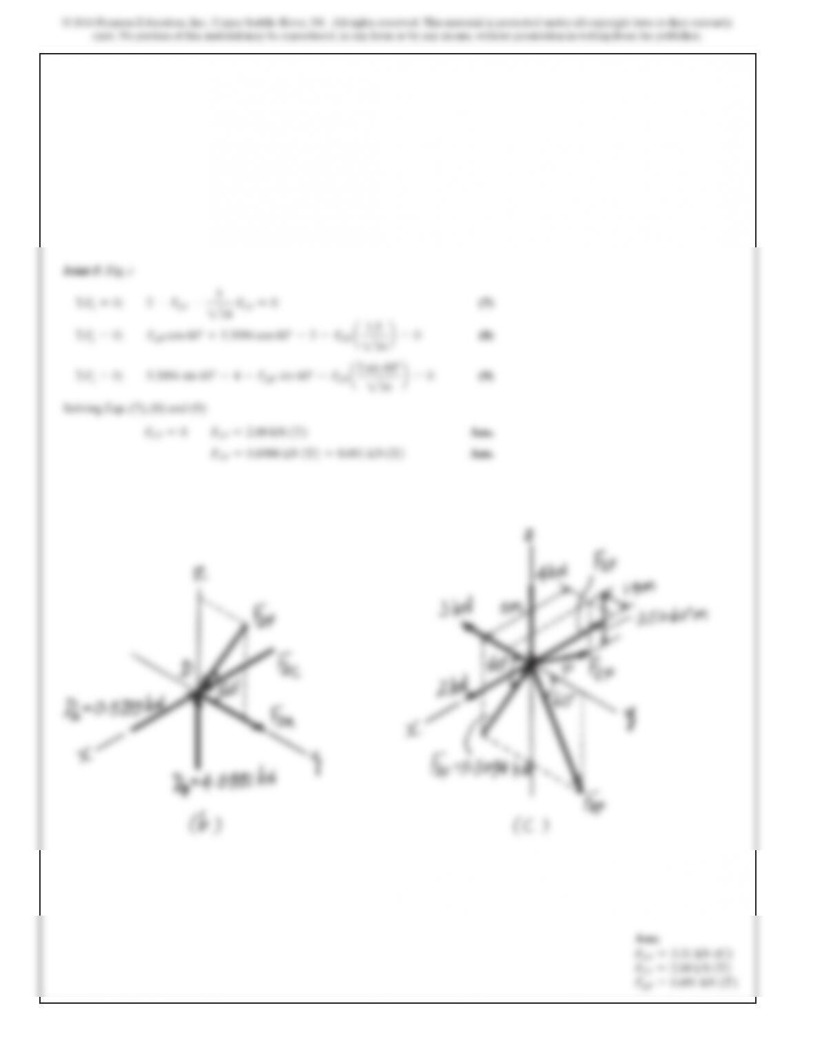
6–57. Continued
549
6–58.
SOLUTION
Joint F:Ans.
Joint B:
Ans.
Ans.
Ans.
Joint A:
Ans.
Ans.
Ans.
Joint E:
Ans.
Ans.F
EF
=300 lb (C)
©F
x
=0;F
EF
–3
5(500) =0
©F
z
=0;F
DE
=0
F
AE
=367 lb (C)
©F
y
=0;F
AE
+300 –4
234 (971.8) =0
F
AD
=0
©F
z
=0;3
234 (971.8) –500 +3
5F
AD
=0
F
AC
=971.8 =972 lb (T)
©F
x
=0;300 +200 –3
234 F
AC
=0
F
AB
=300 lb (C)
©F
x
=0;F
AB
–3
5(500) =0
F
BE
=500 lb (T)
©F
y
=0;400 –4
5F
BE
=0
©F
z
=0;F
BC
=0
F
BF
=0
C
z
=200 lb
D
x
=-200 lb
©F
x
=0;D
x
+200 =0
The space truss is supported by a ball-and-socket joint at D
a
nd short links at Cand E. Determine the force in each
m
ember and state if the members are in tension or
c
ompression. Take and
F
2
=5400j6lb.
F
1
=5200i+300j–500k6lb
3ft
4ft
3ft
x
y
z
C
D
E
A
B
F
F
2
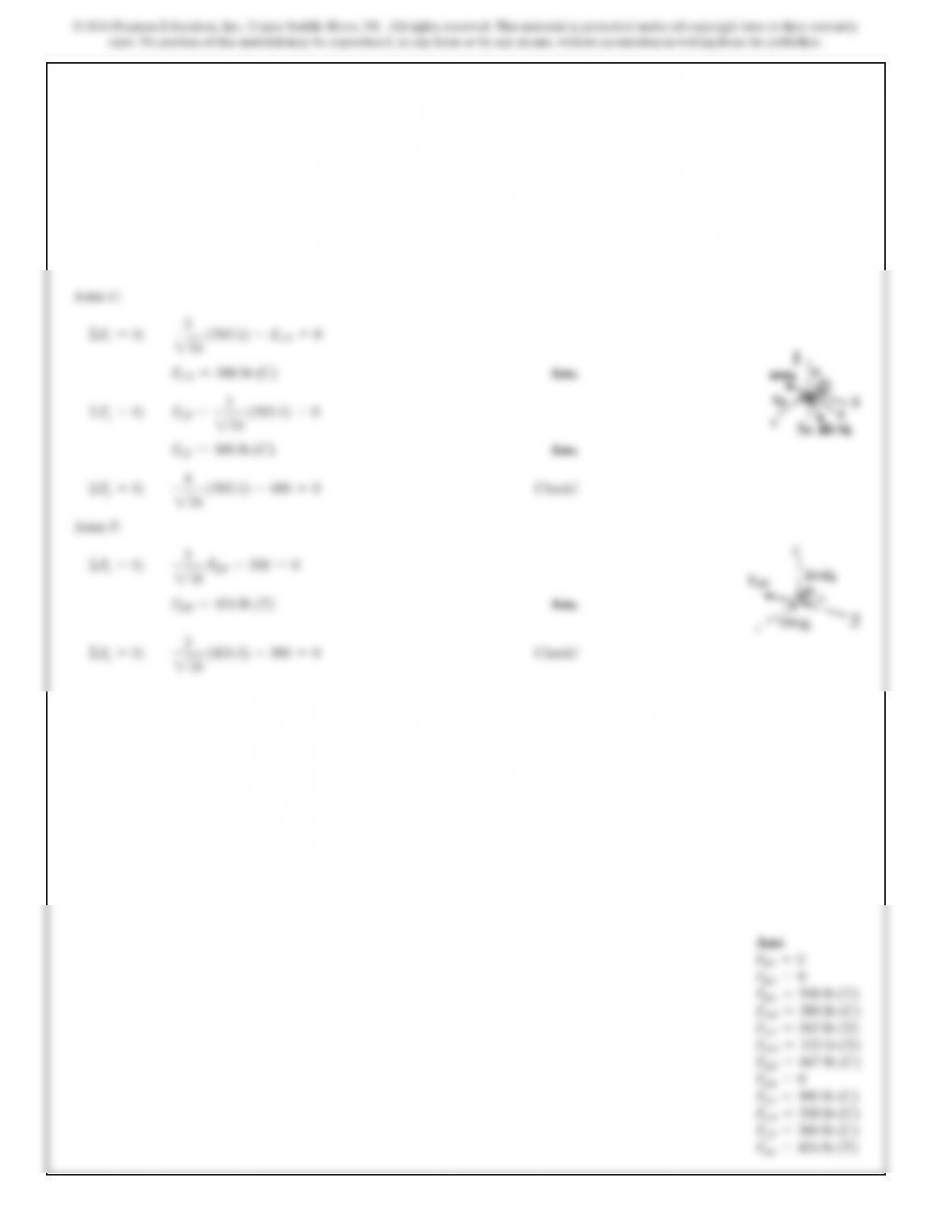
J
o
i
nt C:
Ans.
Ans.
J
oint F:
Ans.F
DF
=424 lb (T)
©F
x
=0;3
218 F
DF
–300 =0
©F
y
=0;4
234 (971.8) –666.7 =0Check!
F
CF
=300 lb (C)
©F
z
=0;F
CF
–3
234 (971.8) +200 =0
F
CD
=500 lb (C)
©F
x
=0;3
234 (971.8) –F
CD
=0
6–58. Continued
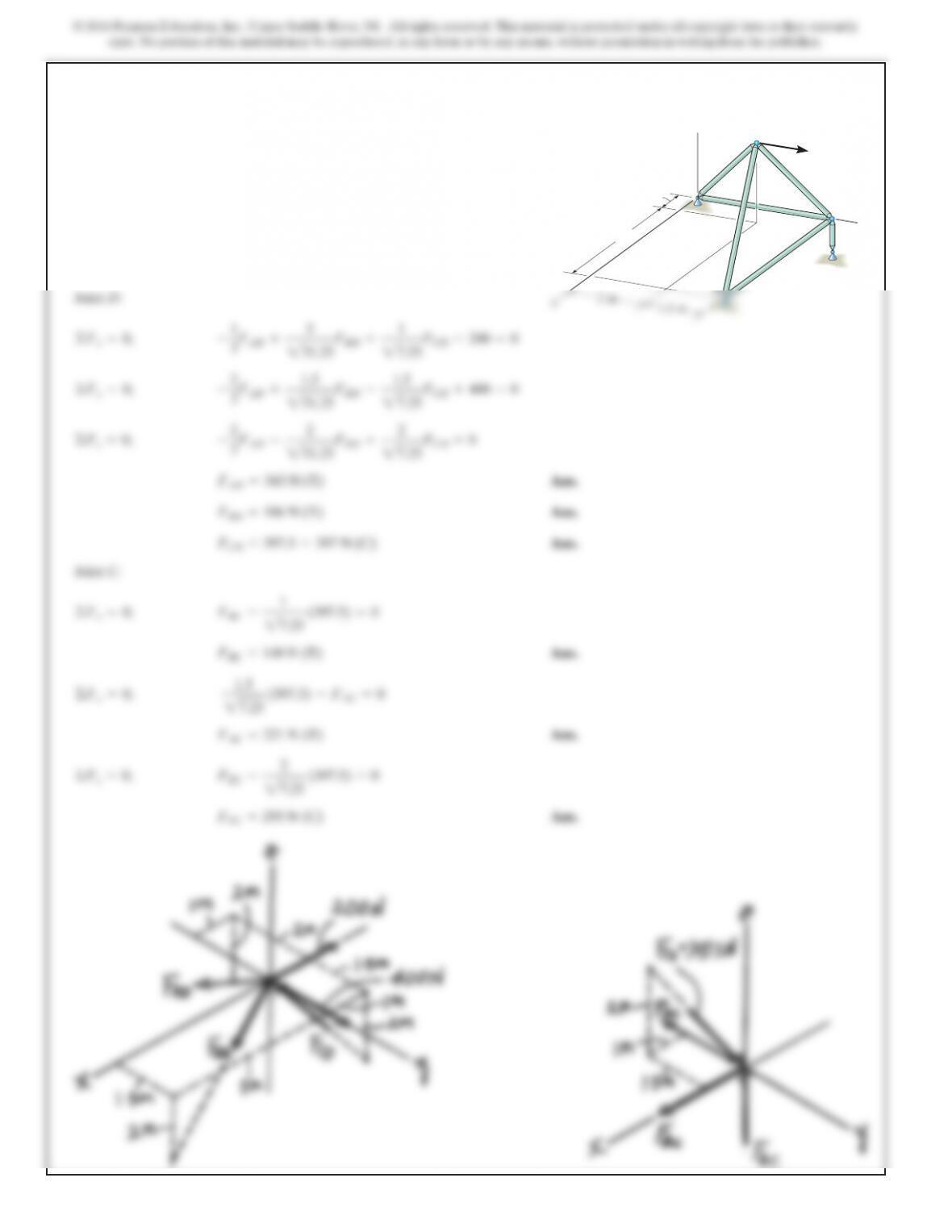
6–59.
Determine the force in each member of the space truss
and state if the members are in tension or compression. The
The truss is supported by ball-and-socket joints at A, B,
and E. Set . Hint: The support reaction at E
acts along member EC. Why?
F=5800j6 N
F
D
A
z
2 m
y
C
E
5 m
1 m
552
*6–60.
Determine the force in each member of the space truss and
state if the members are in tension or compression. The
truss is supported by ball-and-socket joints at A,B, and E.
Set . Hint: The support reaction at E
acts along member EC.Why?
F=5–200i+400j6N
F
D
A
z
2m
y
C
E
5m
1m
SOLUTION
Ans.
Ans.
Ans.
Joint C:
Ans.
Ans.
Ans.FEC =295 N (C)
©Fz=0; FEC –2
27.25 (397.5) =0
FAC =221 N (T)
©Fy=0; 1.5
27.25 (397.5) –FAC =0
FBC =148 N (T)
©Fx=0; FBC –1
27.25 (397.5) =0
FCD =397.5 =397 N (C)
FBD =186 N (T)
FAD =343 N (T)
©Fz=0; –2
3FAD –2
231.25FBD +2
27.25FCD =0
©Fy=0; –2
3FAD +1.5
231.25FBD –1.5
27.25FCD +400 =0
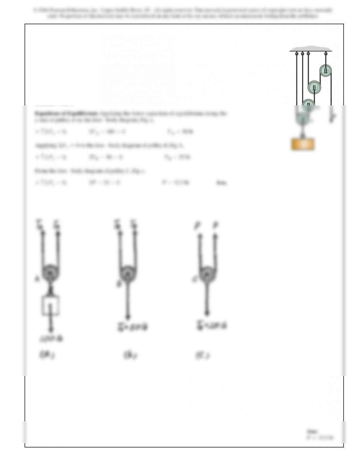
6–61.
Determine the force required to hold the
100-lb weight in equilibrium.
P
SOLUTION
Equations of Equilibrium: Applying the force equation of equilibrium along the
yaxis of pulley Aon the free – body diagram, Fig. a,
Applying to the free – body diagram of pulley B,Fig. b,
From the free – body diagram of pulley C,Fig. c,
Ans.+c©Fy=0; 2P–25 =0P=12.5 lb
+c©Fy=0; 2TB–50 =0TB=25 lb
©Fy=0
+c©Fy=0; 2TA–100 =0TA=50 lb
P
A
B
C
D
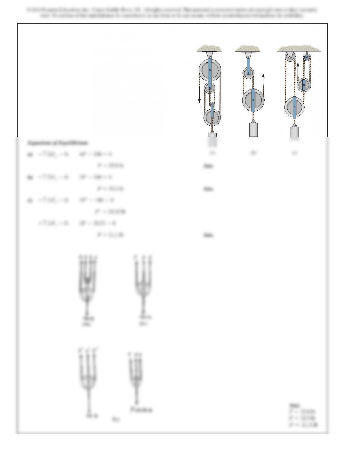
6–62.
SOLUTION
Equations of Equilibrium:
a)
Ans.
Ans.
c)
Ans.P=11.1 lb
3P–33.33 =0+c©F
y
=0;
P¿=33.33 lb
3P¿-100 =0+c©F
y
=0;
P=25.0 lb
4P–100 =0+c©F
y
=0;
In each case, determine the force Prequired to maintain
equilibrium. The block weighs 100 lb.
P
P
P
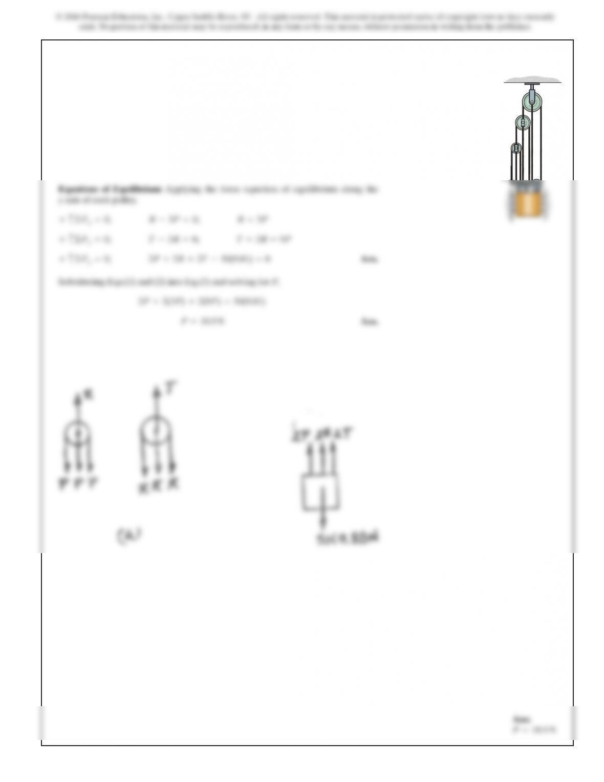
6–63.
Determine the force required to hold the 50-kg mass in
equilibrium.
P
SOLUTION
Ans.
Substituting Eqs.(1) and (2) into Eq.(3) and solving for P,
Ans.P=18.9 N
2P+2(3P)+2(9P)=50(9.81)
+c©Fy=0; 2P+2R+2T–50(9.81) =0
+c©Fy=0; T–3R=0; T=3R=9P
P
A
B
C
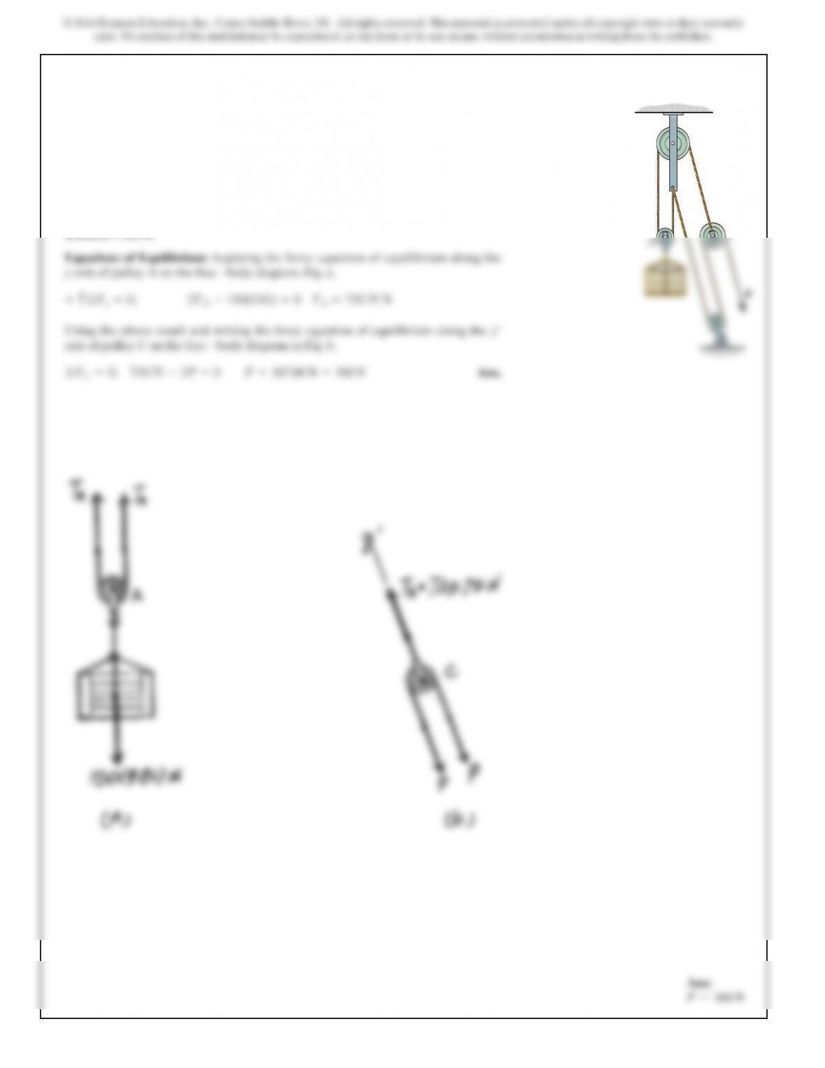
*6–64.
SOLUTION
Using the above result and writing the force equation of equilibrium along the
axis of pulley Con the free – body diagram in Fig. b,
Ans.©Fy¿=0; 735.75 –2P=0P=367.88 N =368 N
y¿
Determine the force required to hold the 150-kg crate
in equilibrium.
P
A
B
C
SOLUTION
5
6–65.
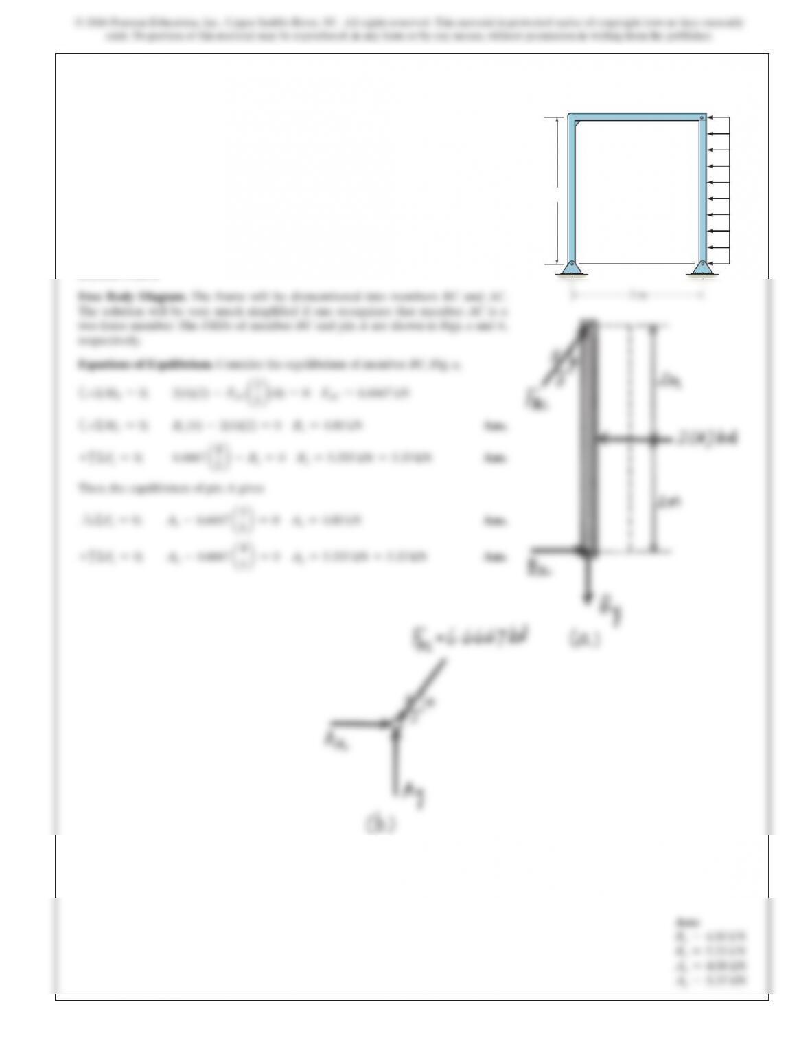
Determine the horizontal and vertical components of force
that pins A and B exert on the frame.
4 m
2 kN/m
A
C
B
SOLUTION
5
5
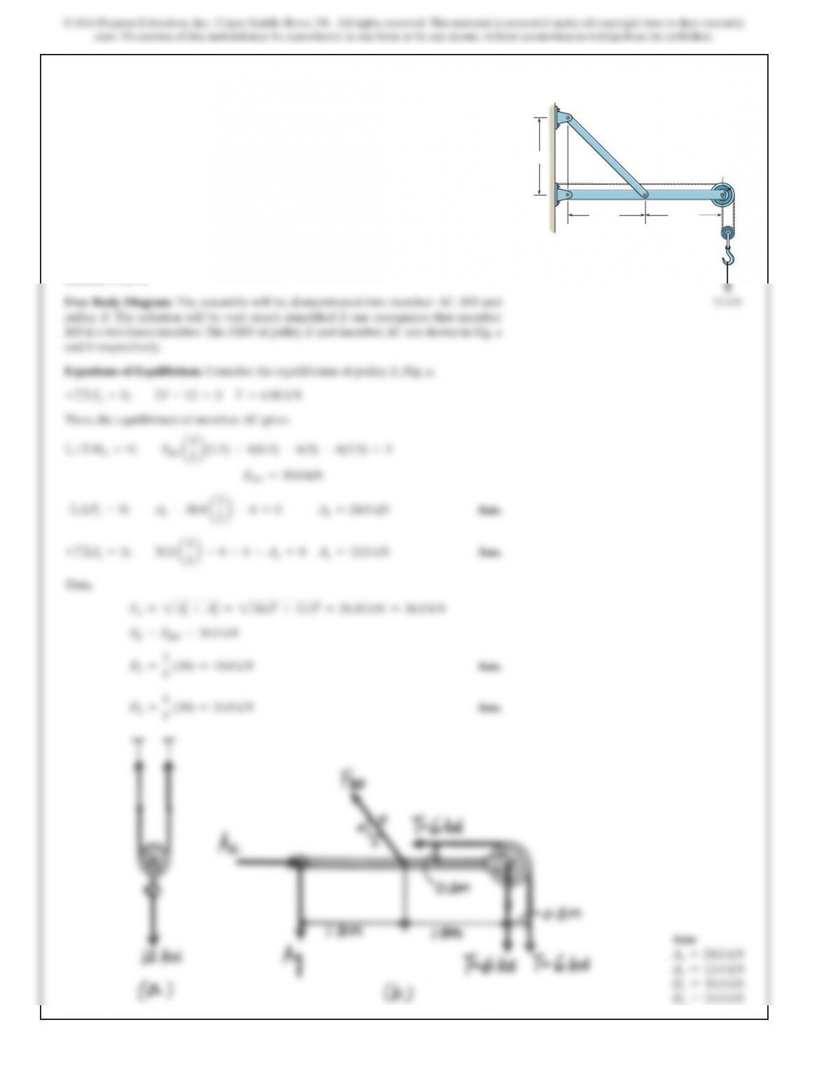
6–66.
Determine the horizontal and vertical components of force
at pins A and D.
1.5 m
D
AB
C
E
1.5 m
0.3 m
2 m
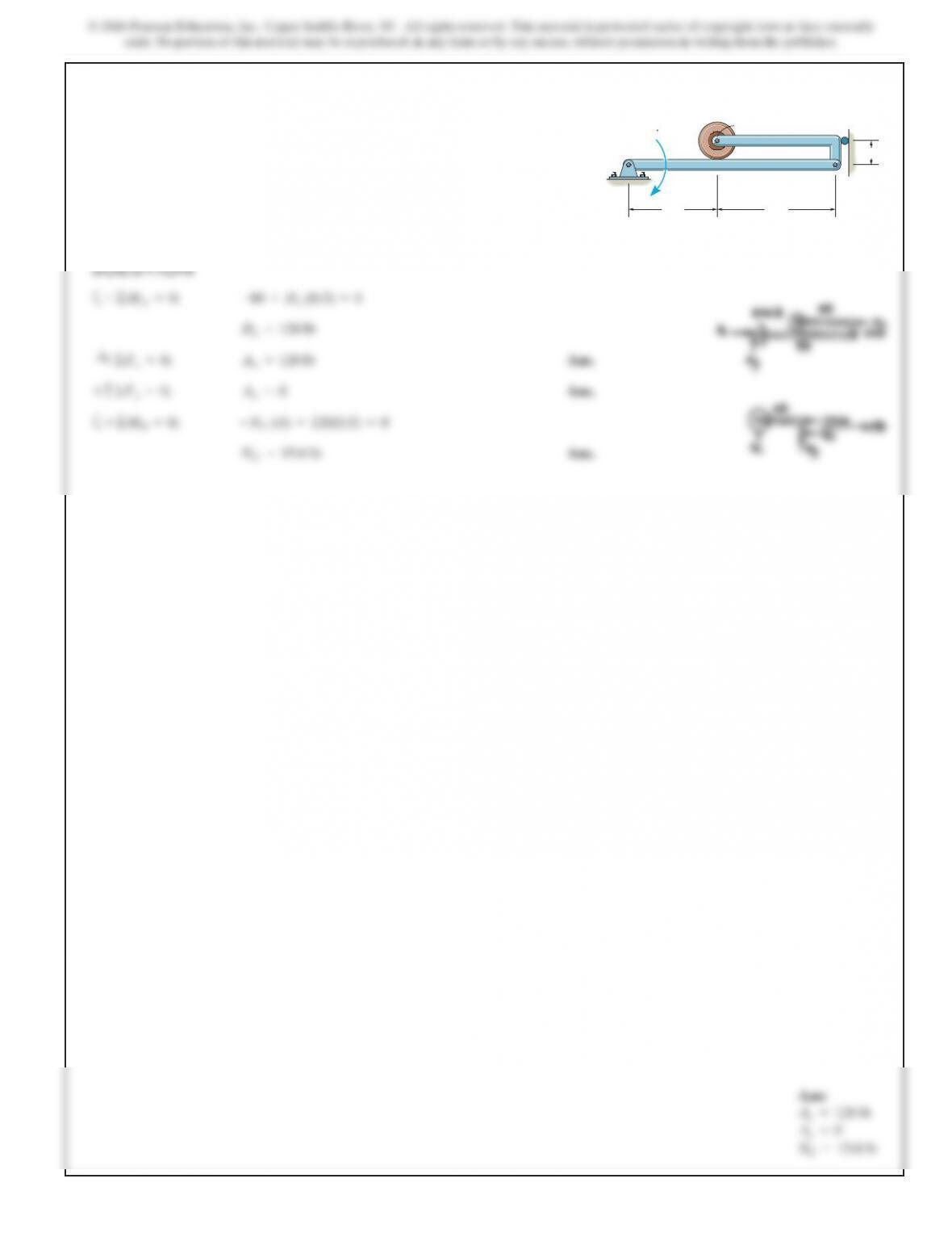
6–67.
SOLUTION
a
Ans.
Ans.
a
Ans.N
C
=15.0 lb
+©M
B
=0; –N
C
(4) +120(0.5) =0
+c©F
y
=0; A
y
=0
:
+©F
x
=0; A
x
=120 lb
D
x
=120 lb
+©M
A
=0;
–60 +D
x
(0.5) =0
Determine the force that the smooth roller Cexerts on
member AB. Also, what are the horizontal and vertical
components of reaction at pin A? Neglect the weight of the
frame and roller.
C
0.5 ft
3ft
A
60 lb ft
4ft
B
D
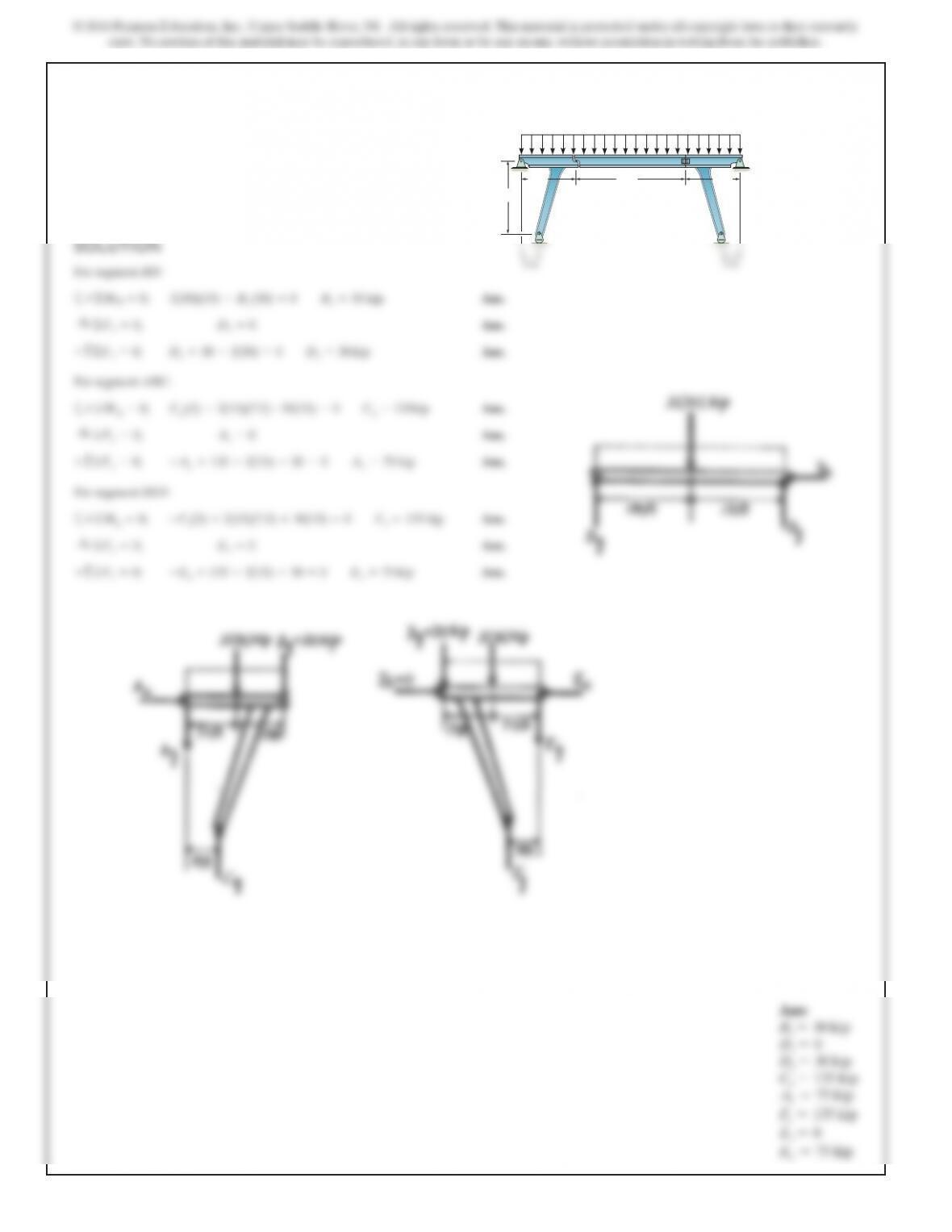
*6–68.
Ans.
Ans.
For segment ABC:
aAns.
Ans.
Ans.
For segment DEF:
aAns.
Ans.
Ans.+c©Fy=0; –Ey+135 –2(15) –30 =0Ey=75 kip
:
+©Fx=0; Ex=0
+©Mg=0; –Fy(5) +2(15)(7.5) +30(15) =0Fy=135 kip
+c©Fy=0; –Ay+135 –2(15) –30 =0Ay=75 kip
:
+©Fx=0; Ax=0
+©MA=0; Cy(5) –2(15)(7.5) –30(15) =0Cy=135kip
+c©Fy=0; Dy+30 –2(30) =0Dy=30 kip
:
+©Fx=0; Dx=0
The bridge frame consists of three segments which can be
considered pinned at A,D, and E, rocker supported at C
and F, and roller supported at B. Determine the horizontal
and vertical components of reaction at all these supports
due to the loading shown.
15 ft
20 ft
15 ft
2kip/ft
30 ft
A
B
CF
D
E