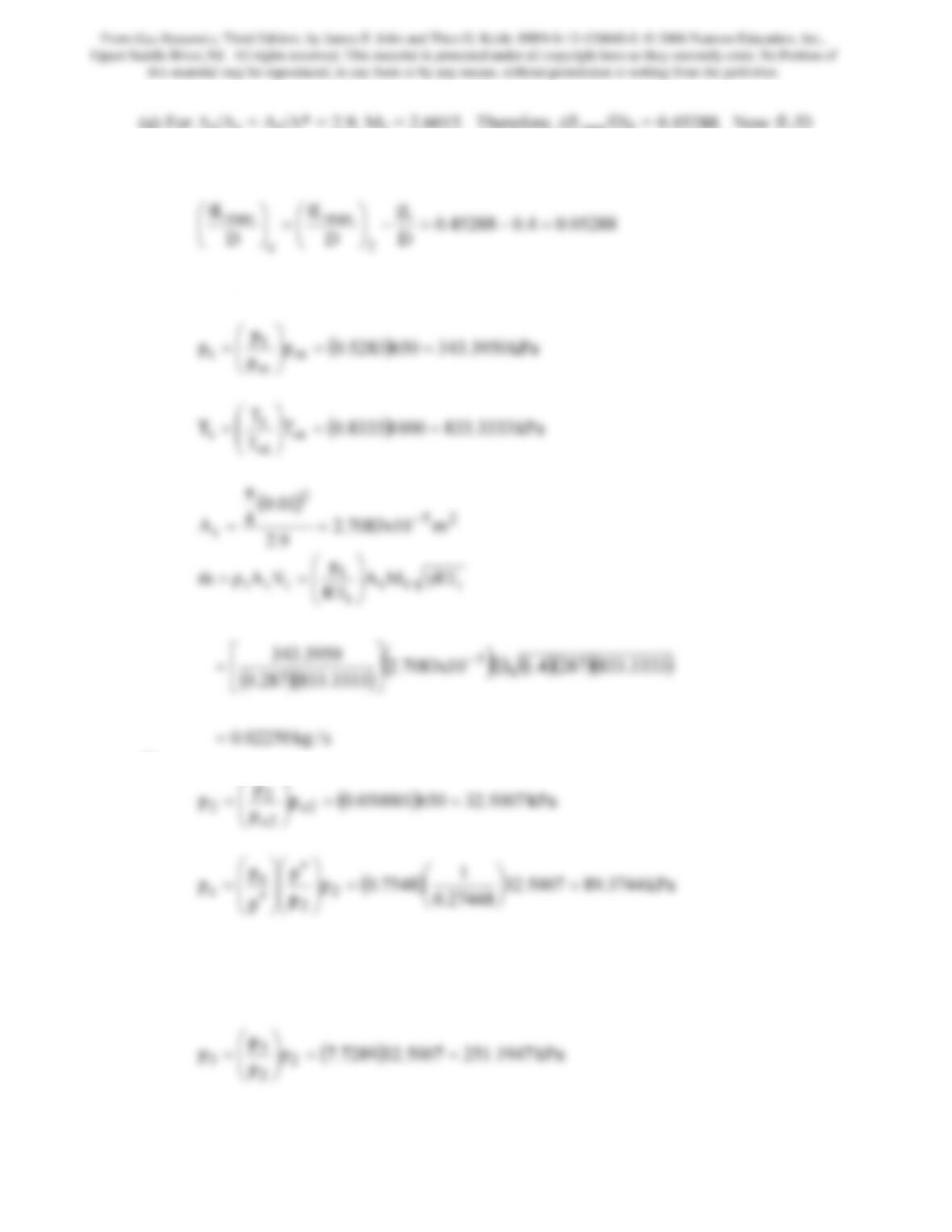
= (0.02)(20)/(1) = 0.4. Hence, L < Lmax so the flow cannot reach Me = 1. To compute the
exit Mach number we have
05288.04.045288.0
D
fL
D
fL
D
fL
2
max
e
max =−=−
⎟
⎠
⎞
⎜
⎝
⎛
=
⎟
⎠
⎞
⎜
⎝
⎛
From which we find Me = 1.2636. Now at the nozzle throat, M = 1 so
p
t
⎞
⎛
()( )
s/kg02250.0
3333.833287.0
=
⎥
⎦
⎢
⎣
(b)
p
2
⎞
⎛
27448.0
p
p
2
⎠
⎝
⎠
⎝
⎠
⎝
(c) In this case a shock stands at the nozzle exit – station 2. We will call the duct inlet,
(on the downstream side of the shock), station 3. Now at M2 = 2.60147, from the
normal shock relations M3 = 0.50374 and p3/p2 = 7.7289. Therefore,
From Gas Dynamics, Third Edition, by James E. John and Theo G. Keith. ISBN 0-13-120668-0. © 2006 Pearson Education, Inc.,
Upper Saddle River, NJ. All rights reserved. This material is protected under all copyright laws as they currently exist. No Portion of
this material may be reproduced, in any form or by any means, without permission in writing from the publisher.
189
Also from the Fanno relations at M3, (fLmax/D)3 = 1.03895. Since fL/D = 0.4 it
follows that
63895.04.003895.1
D
D
D
3
e
⎟
⎠
⎜
⎝
=
⎟
⎠
⎜
⎝
From which we find Me = 0.5668.
12146.2
p
p
3
⎠
⎝
⎠
⎝
⎠
⎝
(d) In this case a shock appears just downstream of the nozzle throat. Consequently,
subsonic flow exits the nozzle. For A2/A1 = A2/A* = 2.9, M2 = 0.2046. Therefore,
(fLmax/D)2 = 13.7780. Since, fL/D = 0.4, then (fLmax/D)e = 13.7780 – 0.4 = 13.3780
from which we find Me = 0.2072
1
p
p
p
p
2o
2
e
⎞
⎛
⎞
⎛
⎞
⎛
⎟
⎞
⎜
⎛
⎟
⎞
⎜
⎛
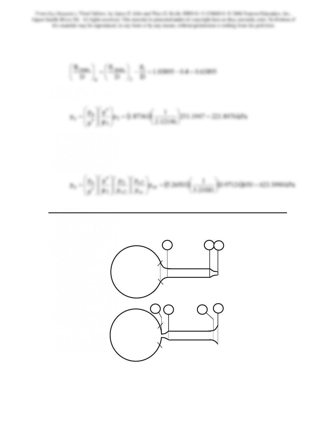
Problem 12. – In which configuration of Figure P9.12, (a) or (b), will the high-pressure
tank empty faster? Explain.
(a)
(b)
Figure P9.12
High
Pressure
Tank
2 3
4
High
Pressure
Tank
2 1
3
4
From Gas Dynamics, Third Edition, by James E. John and Theo G. Keith. ISBN 0-13-120668-0. © 2006 Pearson Education, Inc.,
Upper Saddle River, NJ. All rights reserved. This material is protected under all copyright laws as they currently exist. No Portion of
this material may be reproduced, in any form or by any means, without permission in writing from the publisher.
190
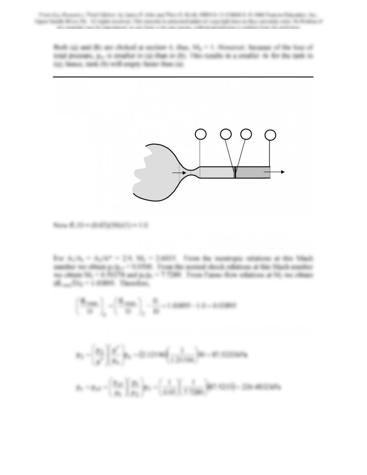
Problem 13. – Air (γ = 1.4 and R = 0.287 kJ/kg · K) flows through a converging-
diverging nozzle with area ratio of 2.9 (Figure P9.13), which exhausts into a constant-
area insulated duct with a length of 50 cm and diameter of 1 cm. If the system back
pressure is 50 kPa, determine the range of reservoir pressures over which a normal shock
will appear in the duct. Let f = 0.02 in the duct.
Figure P9.13
Shock at Duct Inlet
From which we find Me = 0.8455. Consequently,
7289.7
05.0
p
p
2
1
1or =
⎠
⎝
⎠
⎝
⎟
⎠
⎜
⎝
⎟
⎠
⎜
⎝
Shock at Duct Exit
pr
pb = 50 kPa
1 2 e
i
From Gas Dynamics, Third Edition, by James E. John and Theo G. Keith. ISBN 0-13-120668-0. © 2006 Pearson Education, Inc.,
Upper Saddle River, NJ. All rights reserved. This material is protected under all copyright laws as they currently exist. No Portion of
this material may be reproduced, in any form or by any means, without permission in writing from the publisher.
191
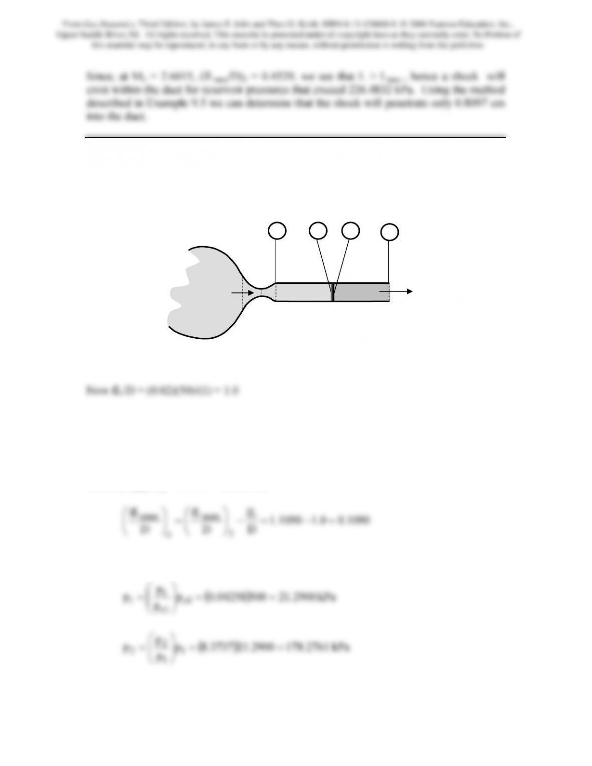
Problem 14. – A converging-diverging nozzle with area ratio of 3.2 (Figure P9.14)
exhausts air (γ = 1.4 and R = 0.287 kJ/kg · K) into a constant-area insulated duct with a
length of 50 cm and diameter of 1 cm. If the reservoir pressure is 500 kPa, determine the
range of back pressures over which a normal shock will appear in the duct (f = 0.02).
Figure P9.14
Shock at Duct Inlet
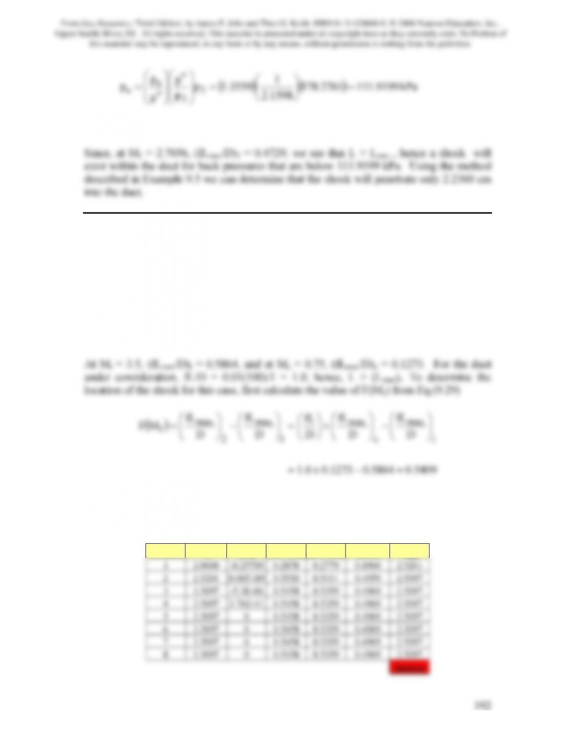
For A1/At = A1/A* = 3.2, M1 = 2.7056. From the isentropic relations at this Mach
number we obtain p1/po1 = 0.04258. From the normal shock relations at this Mach
number we obtain M2 = 0.4952 and p2/p1 = 8.3737. From Fanno flow relations at M2 we
obtain (fLmax/D)2 = 1.1090. Therefore,
From which we find Me = 0.7645. Consequently,
p
1
⎞
⎛
1 2
pr = 500 kPa
pb
e
i
From Gas Dynamics, Third Edition, by James E. John and Theo G. Keith. ISBN 0-13-120668-0. © 2006 Pearson Education, Inc.,
Upper Saddle River, NJ. All rights reserved. This material is protected under all copyright laws as they currently exist. No Portion of
this material may be reproduced, in any form or by any means, without permission in writing from the publisher.
() ()
kPa9199.1112761.178
1598.2
1
3559.1p
p
p
p
p
p2
2
e
e=
⎟
⎠
⎞
⎜
⎝
⎛
=
⎟
⎟
⎠
⎞
⎜
⎜
⎝
⎛
⎟
⎟
⎠
⎞
⎜
⎜
⎝
⎛
=∗
∗
Shock at Duct Exit
Problem 15. – A converging-diverging nozzle is connected to a reservoir containing gas
(γ = 1.4). The area ratio of the nozzle is such that the Mach number is 3.5 exiting the
nozzle and entering a constant-area duct of length-to-diameter ratio, L/D, of 100 to 1 and
friction coefficient of 0.01. (a) Determine the normal shock location, if the Mach number
at the exit is 0.75. (b) With the shock at this location, how much longer can the duct be
made before choking occurs at the exit with no change of Mi? Refer to Figure 9.19 for
the nomenclature.
(a) Determining shock location:
5409.05864.01273.00.1
=−+=
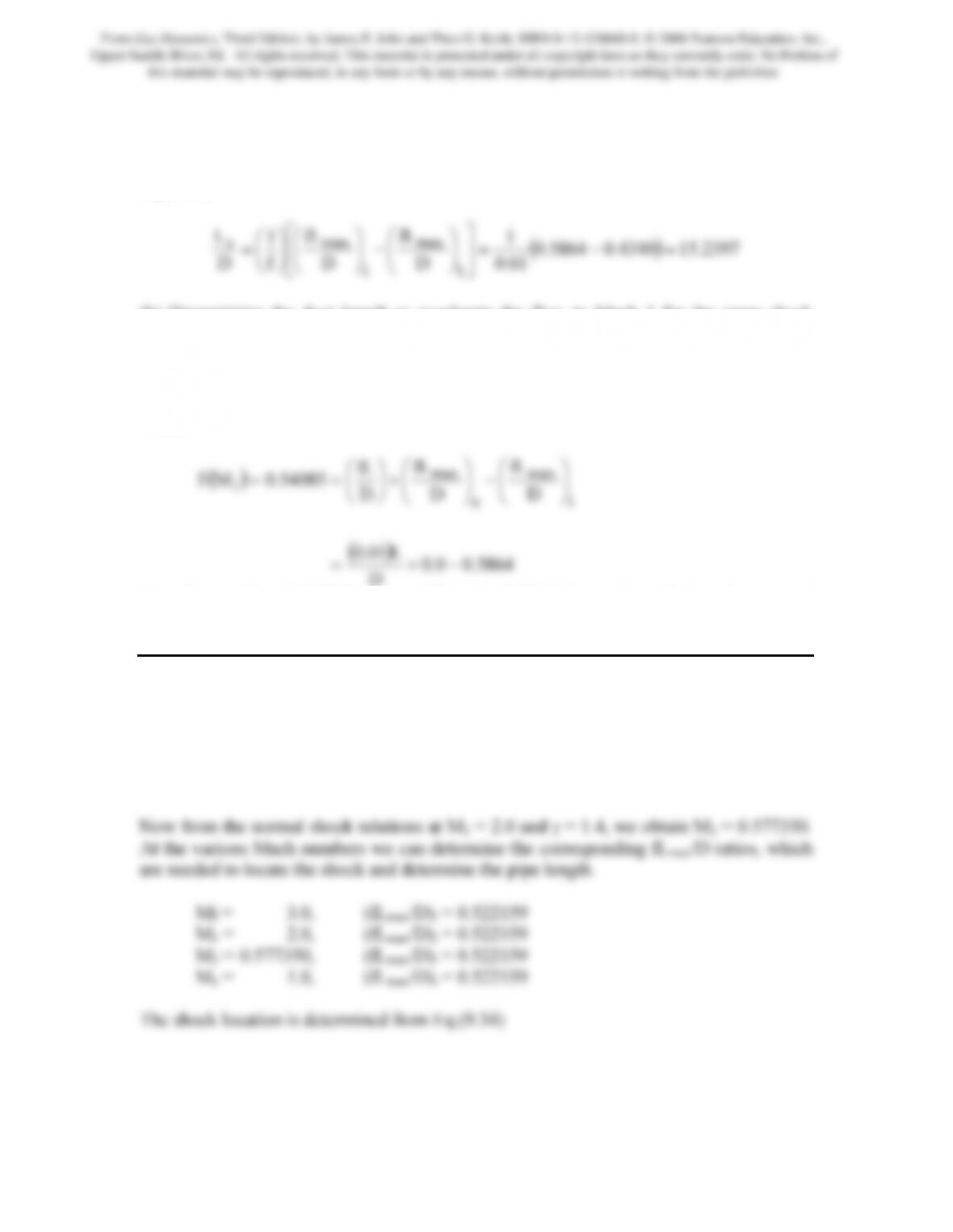
The value of M1 can be obtained by numerically solving Eq.(9.33) using a spreadsheet
program that implements the Newton-Raphson method. The following table contains the
history of the iteration process:
Iteration M f(M) f(M+∆M) f(M-∆M) ∆f/∆M Mnew
From Gas Dynamics, Third Edition, by James E. John and Theo G. Keith. ISBN 0-13-120668-0. © 2006 Pearson Education, Inc.,
Upper Saddle River, NJ. All rights reserved. This material is protected under all copyright laws as they currently exist. No Portion of
this material may be reproduced, in any form or by any means, without permission in writing from the publisher.
193
At M1 = 2.5097, M2 is found from Eq.(9.31) to be 0.5121. At these Mach numbers,
(fLmax/D)1 = 0.4340 and (fLmax/D)2 = 0.9749. The shock location is determined from
Eq.(9.34)
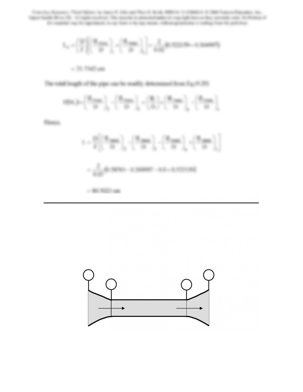
(b) Determining the duct length to accelerate the flow to Mach 1 for the same shock
location determined above.
Because Me = 1.0, (fLmax/D)e = 0.0. Also, because the shock location is fixed
F(M1) = 0.54085 and for the same inlet Mach number, i.e, Mi = 3.5, (fLmax/D)i = 0.5864;
hence,
()
5864.00.0
D
L01.0
−+=
Therefore, L/D = 112.7280 or an additional 12.7280D must be added to the original
length to produce sonic conditions for the same Mi and shock location as in part (a).
Problem 16. – Air (γ = 1.4) enters a pipe of diameter 2 cm at a Mach number of Mi = 3.0.
A normal shock wave stands in the pipe at a location where the Mach number on the
upstream side of the shock is M1 = 2.0. The Mach number exiting the pipe is Me = 1.0.
For steady, adiabatic, one-dimensional flow in the pipe, i.e., Fanno flow, determine the
location of the shock and the total length of the pipe. Assume f = 0.02.
From Gas Dynamics, Third Edition, by James E. John and Theo G. Keith. ISBN 0-13-120668-0. © 2006 Pearson Education, Inc.,
Upper Saddle River, NJ. All rights reserved. This material is protected under all copyright laws as they currently exist. No Portion of
this material may be reproduced, in any form or by any means, without permission in writing from the publisher.
194
2
fL
fL
D
max
max
⎤
⎡⎟
⎞
⎛
⎞
⎛
⎞
⎛
cm5023.80
02.0
=
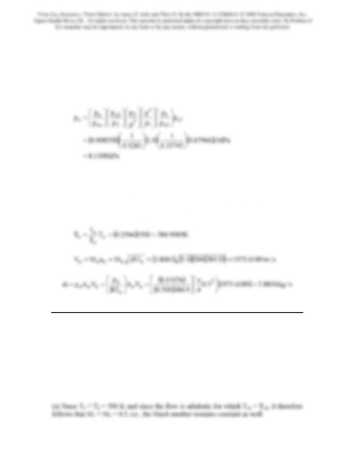
Problem 17. – A rocket nozzle is operating with a stretched out throat, (L = 50 cm and
D = 10 cm) as shown in Figure P9.17. If the inlet stagnation conditions are po1 = 1 MPa
and To1 = 1500 K, determine the nozzle exit velocity and mass flow for a back pressure of
30 kPa. The diameter of the nozzle at the exit station is the same as at the inlet station:
30 cm. Treat the exhaust gases as perfect, with γ = 1.4 and R = 0.50 kJ/kg · K. Assume
isentropic flow in variable-area sections and Fanno flow in constant-area sections with
f = 0.22.
Figure P9.17
i
1 2
e
From Gas Dynamics, Third Edition, by James E. John and Theo G. Keith. ISBN 0-13-120668-0. © 2006 Pearson Education, Inc.,
Upper Saddle River, NJ. All rights reserved. This material is protected under all copyright laws as they currently exist. No Portion of
this material may be reproduced, in any form or by any means, without permission in writing from the publisher.
Assume the system is choked so that M2 = 1 and (fLmax/D)2 = 0. Also, (p/po)2 = 0.5253
and p2 = p*. Now fL/D = (0.022)(50)/(10) = 0.110 = (fLmax/D)1. The corresponding
Mach number to this value is M1 = 0.7637. At this Mach number from the isentropic
relations: (p/po)1 = 0.67966 and from the Fanno flow relations: (p/p*)1 = 1.35745.
Now for an area ratio of 9, from the isentropic relations we find that Me = 3.8061. At this
Mach number from the isentropic relations: (p/po)e = 0.0.008558. Therefore,
kPa1108.8
35745.1
5283.0
=
⎠
⎝
⎠
⎝
If there is a normal shock at the exit, the pressure ratio across the shock is: (pe2/pe1) =
16.7337. Therefore, pe2 = pb = 135.7230 kPa. Because this is well above the stated back
pressure of 30 kPa, pe = 8.1108 kPa and the flow is further compressed outside the nozzle
by oblique shocks.
At Me = 3.8061 from the isentropic relations, (T/To)e = 0.2566. Hence,
Problem 18. – Air (γ = 1.4 and R = 0.287 kJ/kg · K) flows adiabatically in a tube of
circular cross section with an initial Mach number of 0.5, initial T1 = 500 K, and
pl = 600 kPa. The tube is to be changed in cross-sectional area so that, taking friction into
account, there is no change in the temperature of the stream. Assume the distance
between inlet and exit, L, is equal to 100 Dl, with Dl = initial duct diameter; f = 0.02. Find
the following:
(a) Mach number M2
(b) D2/Dl
(c) Static pressure p2
From Gas Dynamics, Third Edition, by James E. John and Theo G. Keith. ISBN 0-13-120668-0. © 2006 Pearson Education, Inc.,
Upper Saddle River, NJ. All rights reserved. This material is protected under all copyright laws as they currently exist. No Portion of
this material may be reproduced, in any form or by any means, without permission in writing from the publisher.
196
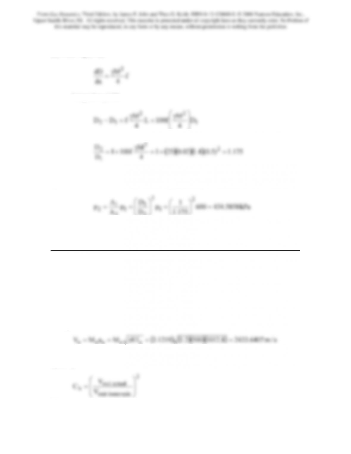
(b) From Eq.(9.42)
Integration yields
1
12 D
4
4
⎠
⎜
⎝
Hence,
4
M
D
D2
2
1
2=+=
γ
(c) Since both the static temperature and the Mach number are constant, then so are the
speed of sound and the velocity. Accordingly, p1A1 = p2A2. So that
175.1
D
A
2
2
⎠
⎝
⎠
⎝
Problem 19. – In a rocket nozzle of area ratio 8 to 1, combustion gases (γ = 1.2 and
R = 0.50 kJ/kg · K) are expanded from a chamber pressure and temperature of 5 MPa and
2000 K. For a nozzle coefficient Ch equal to 0.96, determine the rocket exhaust velocity
in space.
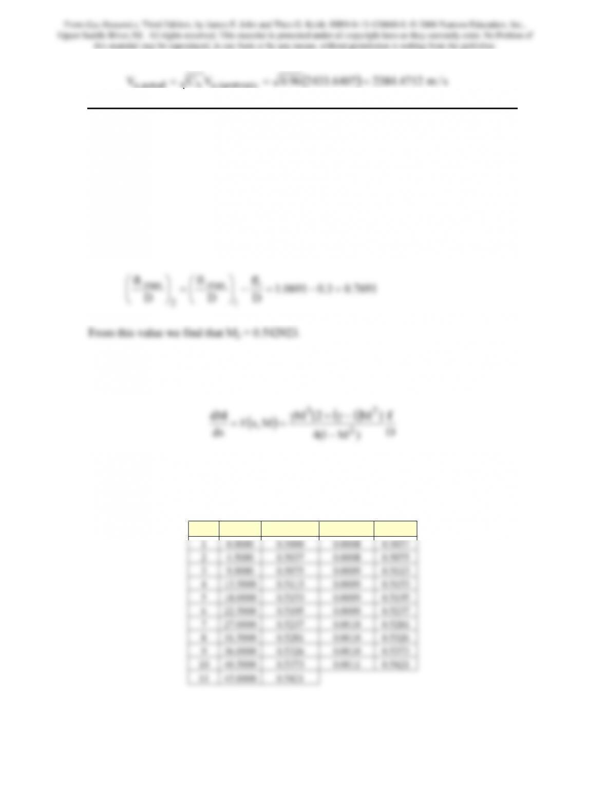
From the isentropic relations with γ = 1.2 and an area ratio, A/A* = 8, the supersonic
solution is M = 3.1219. The corresponding temperature ratio T/To = 0.5064.
Accordingly, the exit temperature is Te = (0.5064)(2000) = 1012.8 K. The exit velictiy is
readily determined as follows:
This is the exit velocity for isentropic flow. The actual exit velocity is related to this
speed by
ropicexit isent
hV
⎠
⎜
⎝
Hence,
From Gas Dynamics, Third Edition, by James E. John and Theo G. Keith. ISBN 0-13-120668-0. © 2006 Pearson Education, Inc.,
Upper Saddle River, NJ. All rights reserved. This material is protected under all copyright laws as they currently exist. No Portion of
this material may be reproduced, in any form or by any means, without permission in writing from the publisher.
(
)
s/m4712.23846407.243396.0VCV isentropic,ehactual,e ===
Problem 20. – Air (γ = 1.4) enters a constant-area, insulated duct (Figure 9.9) with a
Mach number of 0.50. The duct length is 45 cm; the duct diameter is 3 cm; and the
friction coefficient is 0.02. Use Euler’s explicit method on a coarse grid containing 11
grid points to determine the Mach number at the duct outlet. Compare the result obtained
to the value obtained using Fanno relations.
Exact Solution
From the Fanno relations at M1 = 0.5, (fLmax/D)1 = 1.0691. Also, from the given
information fL/D = 0.3. Hence,
7691.03.00691.1
D
D
D
1
2
⎟
⎠
⎜
⎝
=
⎟
⎠
⎜
⎝
Numerical Solution
Proceeding as in Example problem 9.9, we have
D
f
)M1(4
]M12[M
dx
dM
2
23
−
−γ+γ
The same grid in the example is used here in which the duct length is divided into 10
evenly spaced increments, i.e., ∆x = 4.5 cm. The computations are straightforward and
the results from a spreadsheet program are
pt x Mi F(xi,Mi) Mi+1
From Gas Dynamics, Third Edition, by James E. John and Theo G. Keith. ISBN 0-13-120668-0. © 2006 Pearson Education, Inc.,
Upper Saddle River, NJ. All rights reserved. This material is protected under all copyright laws as they currently exist. No Portion of
this material may be reproduced, in any form or by any means, without permission in writing from the publisher.
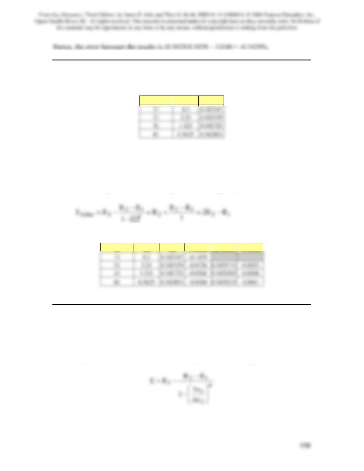
Hence, the error between the results is (0.5421/0.5429 – 1)100 = -0.1429%.
Problem 21. –If the problem described in the above is solved on finer grids using the first
order Euler explicit method, the following results for the exit Mach number are obtained
n ∆x Me
Determine the error when compared to the exact value of the exit Mach number is
0.542923. Use Richardson’s extrapolation method to obtain improved values. Also,
compute the error of these values.
Richardson’s extrapolation for Euler’s explicit method is given by
()
12
2
1
2Euler RR2
1
21
−
Using this relation, the following table is easily prepared
n ∆x Me % error Me (Extr) % error
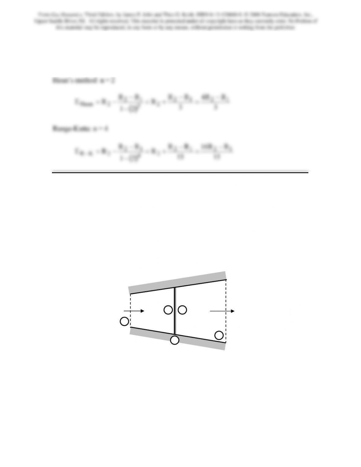
Problem 22. – Heun’s predictor-corrector method is 2nd order and the Runge-Kutta
method used in this Chapter is 4th order. Obtain an expression for each of these methods
that could be used to perform Richardson’s extrapolation of results, R2 and R1 that were
determined on two grids that differ by a factor of two, i.e., ∆x2 = ∆x1/2.
The extrapolated value, E, in Richardson’s extrapolation method, is given by
From Gas Dynamics, Third Edition, by James E. John and Theo G. Keith. ISBN 0-13-120668-0. © 2006 Pearson Education, Inc.,
Upper Saddle River, NJ. All rights reserved. This material is protected under all copyright laws as they currently exist. No Portion of
this material may be reproduced, in any form or by any means, without permission in writing from the publisher.
199
where R1 and R2 are the values that have been computed using the same method on two
grids of known width, say ∆x1 and ∆x2. Also, the accuracy of the method is of order n.
For this problem ∆x1 = 2∆x2. Thus,
Problem 23. – An airstream (γ = 1.4, R = 0.287 kJ/kg·K) at Mach 2.0 with a pressure of
100 kPa and a temperature of 270 K, enters a diverging, linear, conical channel with a
ratio of exit area to inlet area of 3.0 (see Figure P9.23). The inlet area is 0.008 m2 and the
length is 10.0 cm. The average friction factor is 0.03. Use Heun’s predictor-corrector
method on a coarse grid of 11 grid points to determine the back pressure, pb, necessary to
produce a normal shock in the channel at 5 cm from the inlet. Assume one-dimensional,
steady flow with the air behaving as a perfect gas with constant specific heats. Compare
results to the pressure value obtained by assuming isentropic flow except across the
normal shock (see Example 4.3). Does friction significantly change the isentropic flow
results?
Figure P9.23
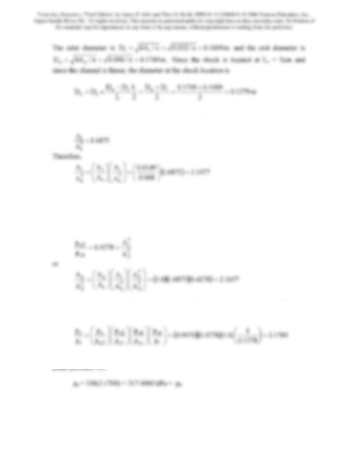
Solution Using Fanno Flow, Isentropic Flow and Normal Shock Relations
Ai
Ae
2 1
ie
is
A3A
A2A
=
=
e
i
s
From Gas Dynamics, Third Edition, by James E. John and Theo G. Keith. ISBN 0-13-120668-0. © 2006 Pearson Education, Inc.,
Upper Saddle River, NJ. All rights reserved. This material is protected under all copyright laws as they currently exist. No Portion of
this material may be reproduced, in any form or by any means, without permission in writing from the publisher.
200
2
2
2
L
is =
Therefore the area at the shock is As = A1 = πDs2/4 = 0.0149 m2. At Mi = 2.0, from the
isentropic relations with γ = 1.4,
008.0
A
A
A
*
1
i
*
1
⎠
⎝
⎟
⎠
⎜
⎝
⎟
⎠
⎜
⎝
Using the Newton-Raphson iterative procedure and taking the supersonic root because
the flow on the upstream side of the shock must be supersonic, we obtain M1 = 2.6882.
Note the Mach number on the downstream side of the shock is found to be 0.4966. With
the upstream shock Mach number determined, ratios of properties across the shock can be
found from normal shock relations, which are then combined with Eq.(4.21) to give
*
1
2o
A
4278.0
p==
Again, using the Newton-Raphson procedure, this area ratio produces the following
subsonic value at the exit: Me = 0.2800. We can now solve for the exit pressure, pe:
1278.0
p
p
p
p
p
i
oi
1o
2o
i
⎠
⎝
⎟
⎠
⎜
⎝
⎟
⎠
⎜
⎝
⎟
⎠
⎜
⎝
⎟
⎠
⎜
⎝
With subsonic flow at the channel exit, the channel back pressure is equal to the exit
Solution Obtained by Solving ODE Using Heun’s Method and Normal Shock Relations
From Gas Dynamics, Third Edition, by James E. John and Theo G. Keith. ISBN 0-13-120668-0. © 2006 Pearson Education, Inc.,
Upper Saddle River, NJ. All rights reserved. This material is protected under all copyright laws as they currently exist. No Portion of
this material may be reproduced, in any form or by any means, without permission in writing from the publisher.
201
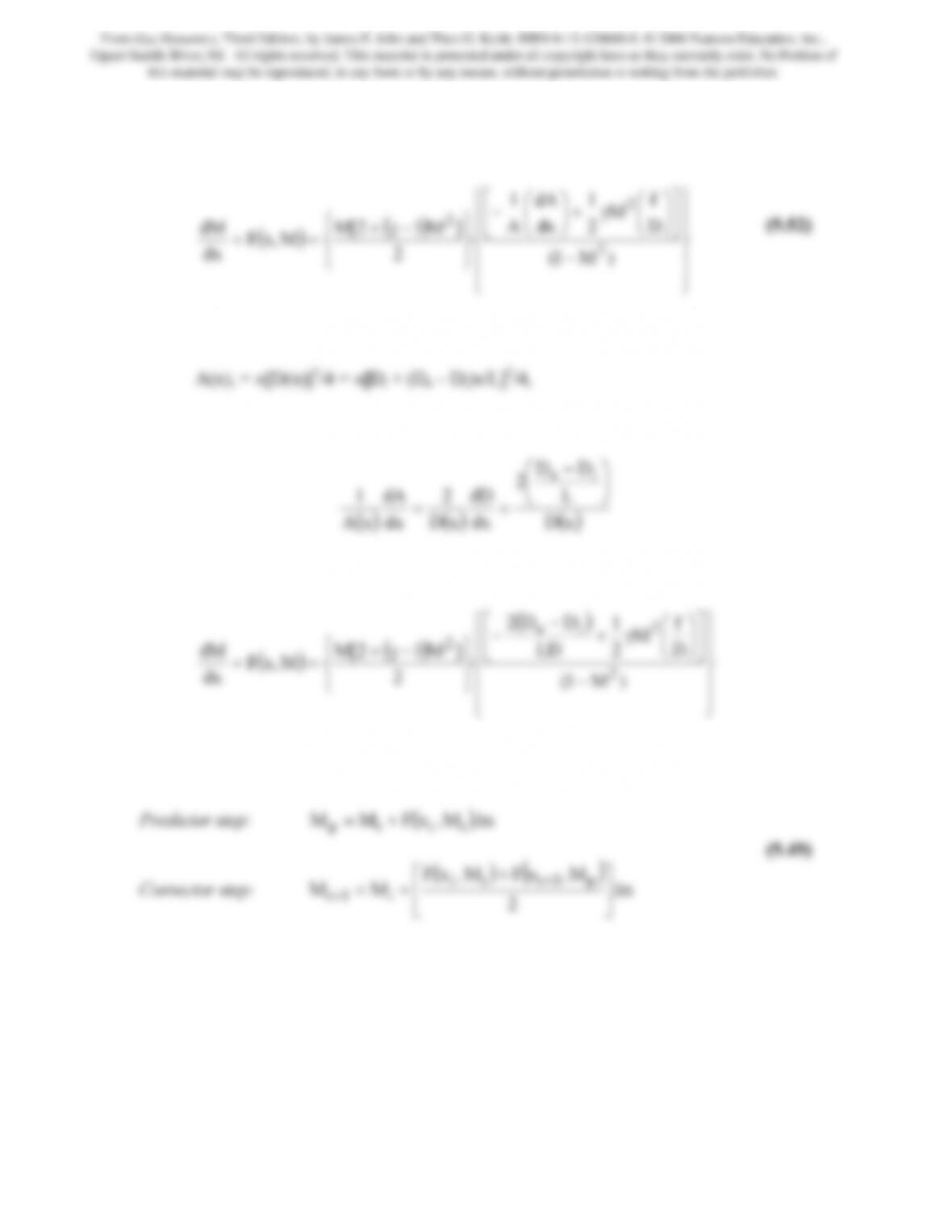
The equation which governs the Mach number distribution within the channel when both
area variation and frictional effects are considers is
() ()
⎪
⎪
⎭
⎪
⎪
⎬
⎫
⎪
⎪
⎩
⎪
⎪
⎨
⎧
−
⎥
⎦
⎤
⎢
⎣
⎡⎟
⎠
⎞
⎜
⎝
⎛
γ+
⎟
⎠
⎞
⎜
⎝
⎛
−
⎪
⎭
⎪
⎬
⎪
⎩
⎪
⎨
==
)M1(
D
f
M
2
1
dx
dA
A
1
2
]M12[M
M,xF
dx
dM
2
2
2 (9.52)
Since the nozzle is conical, the local cross sectional area is given by
Thus the area term in Eq(9.52) can be written as
() () ()
xD
dx
xD
dx
xA
Consequently, Eq.(9.52) becomes
() () ()
⎪
⎪
⎭
⎪
⎪
⎬
⎫
⎪
⎪
⎩
⎪
⎪
⎨
⎧
−
⎥
⎦
⎤
⎢
⎣
⎡⎟
⎠
⎞
⎜
⎝
⎛
γ+
−
−
⎪
⎭
⎪
⎬
⎪
⎩
⎪
⎨
==
)M1(
D
f
M
2
1
LD
DD2
2
]M12[M
M,xF
dx
dM
2
2
ie
2
where D = D(x) = Di + (De – Di)x/L. Heun’s method is
2
⎦
⎣
where Mp is the predicted Mach number.
For this problem, we will divide L into 10 pieces of uniform length, i.e., the grid spacing
is therefore ∆x = 1 cm = 0.01 m.
First, we will assume that f = 0. Inserting Mi and the given information into F(x,M) at
x = 0 results in F(0.0,2.0) = 17.5692 and for the grid spacing we can compute the
predicted Mach number, i.e., Mp to be 0.2.1757. This is then used to compute
From Gas Dynamics, Third Edition, by James E. John and Theo G. Keith. ISBN 0-13-120668-0. © 2006 Pearson Education, Inc.,
Upper Saddle River, NJ. All rights reserved. This material is protected under all copyright laws as they currently exist. No Portion of
this material may be reproduced, in any form or by any means, without permission in writing from the publisher.
202
F(∆x,Mp) = 15.4760. Hence, M2 =2.1602. The static pressures at each x are computed
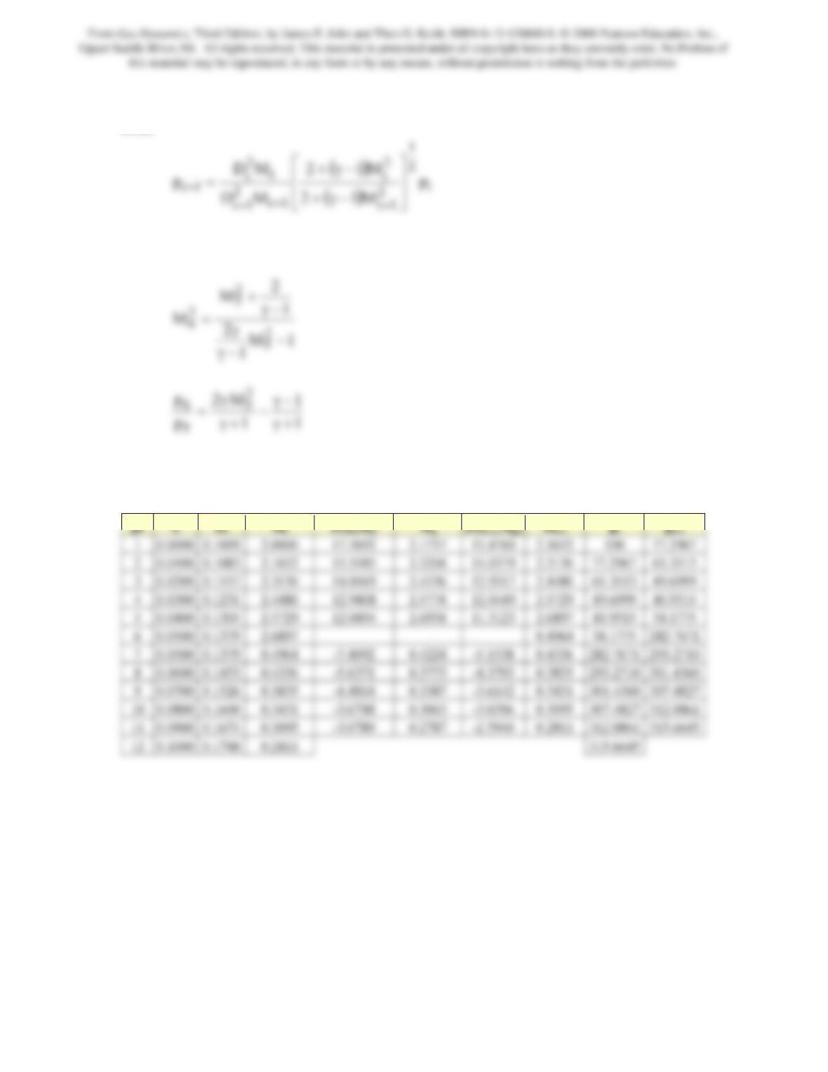
from
1
2
2
⎤
⎡
Across the shock located at x = 0.05 m, the normal shock relations are used, viz.,
1
1
p
5
+γ
+γ
The results of the calculations for f = 0 obtained from a spreadsheet program are
presented in the following
The computed exit pressure is 315.6645 kPa, which differs from the value computed
from Fanno relations, i.e., 317.0000kPa by –0.4213%. This is very good for the
particularly coarse mesh used in the computations.
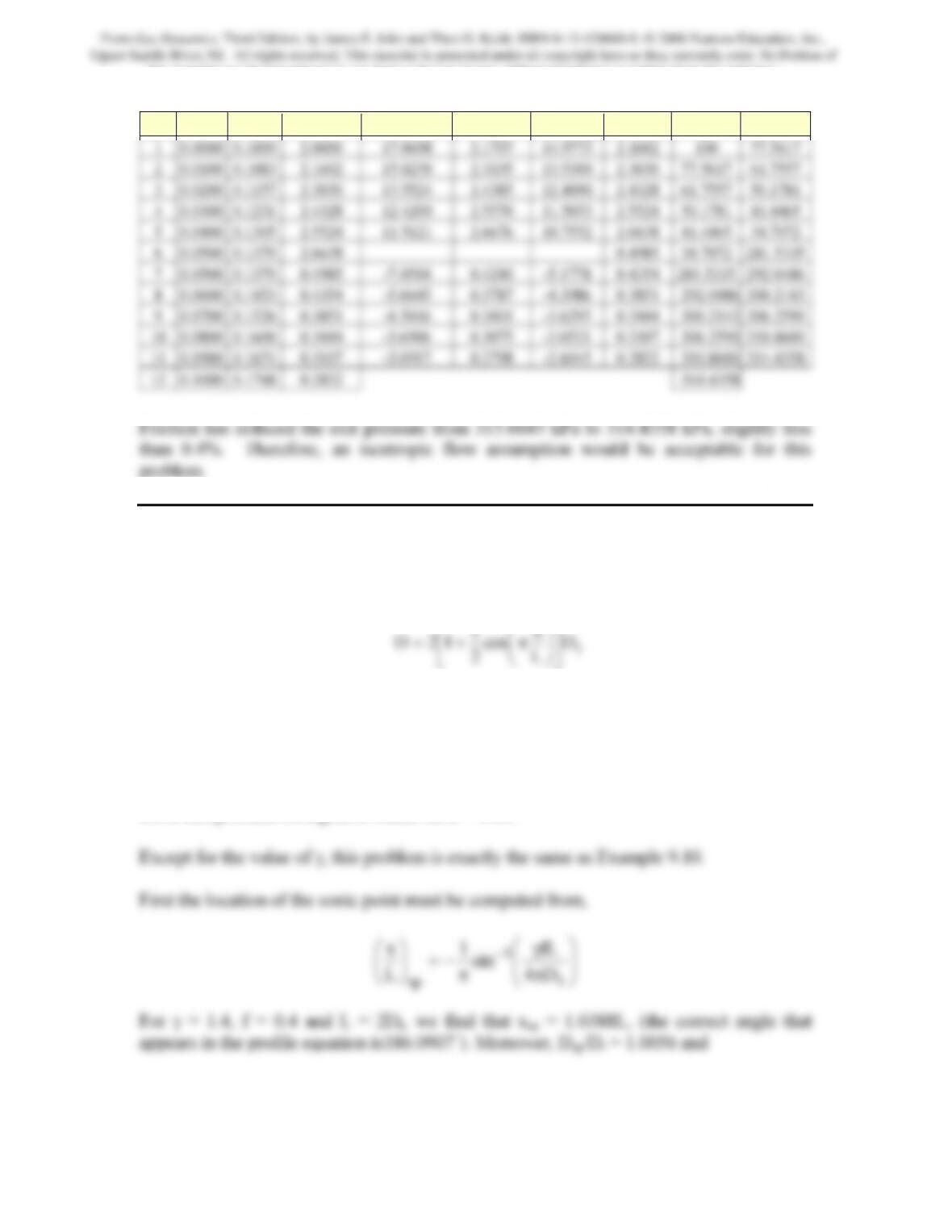
Repeating the calculations for f = 0.03, we obtain,
From Gas Dynamics, Third Edition, by James E. John and Theo G. Keith. ISBN 0-13-120668-0. © 2006 Pearson Education, Inc.,
Upper Saddle River, NJ. All rights reserved. This material is protected under all copyright laws as they currently exist. No Portion of
this material may be reproduced, in any form or by any means, without permission in writing from the publisher.
203
pt x Di Mi F(xi,Mi) Mp F(xi+1,Mp) Mi+1 pi pi+1
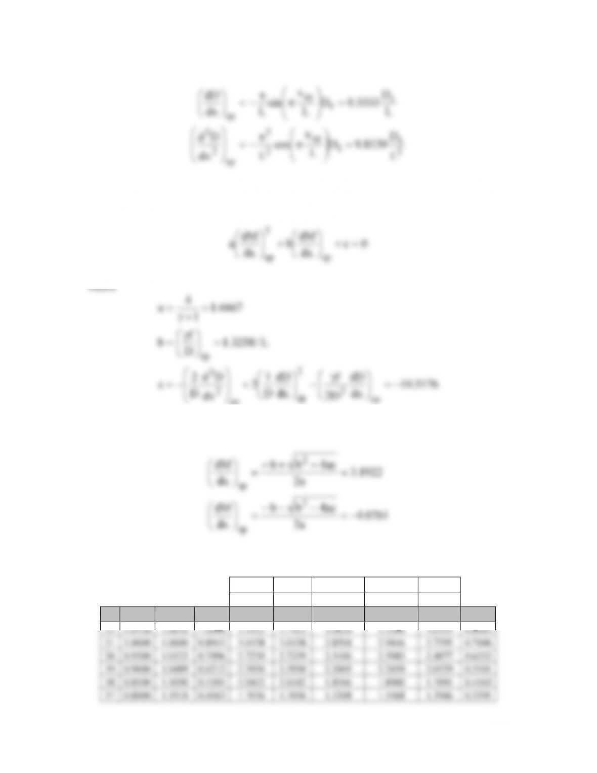
Problem 24. – Helium (γ = 5/3) flows through a symmetrical, C-D nozzle with a circular
cross-section. The shape of the nozzle is given by
t
D
L
x
cos
2
1
12D ⎥
⎦
⎤
⎢
⎣
⎡⎟
⎠
⎞
⎜
⎝
⎛π+=
The nozzle length is two times the throat diameter, i.e., L = 2Dt. Assuming that the
nozzle is choked, determine the Mach number distribution for both subsonic and
supersonic flow in the diverging portion of the nozzle. Assume that the friction
coefficient is 0.4. Use the Method of Beans and the 4th order Runge-Kutta method to
solve this problem on a grid in which ∆x/L = 0.05.
From Gas Dynamics, Third Edition, by James E. John and Theo G. Keith. ISBN 0-13-120668-0. © 2006 Pearson Education, Inc.,
Upper Saddle River, NJ. All rights reserved. This material is protected under all copyright laws as they currently exist. No Portion of
this material may be reproduced, in any form or by any means, without permission in writing from the publisher.
204
2
t
t
sp
2
2
sp
2
2
L
D
8139.9D
L
x
cos
Ldx
Dd
=
⎟
⎟
⎠
⎞
⎜
⎜
⎝
⎛π
π
−=
⎟
⎟
⎠
⎞
⎜
⎜
⎝
⎛
The slopes that are used to begin the solution at the sonic point must be computed. This is
accomplished by solving the following quadratic
0c
dx
b
dx
a
sp
sp
=+
⎟
⎠
⎜
⎝
+
⎟
⎠
⎜
⎝
5176.19
dx
dD
D2
f
dx
dD
D
1
2
dx
Dd
D
2
c
D
sp
2
2
sp
sp
2
2
sp
−=
⎟
⎟
⎠
⎞
⎜
⎜
⎝
⎛γ
−
⎟
⎠
⎞
⎜
⎝
⎛
+
⎟
⎟
⎠
⎞
⎜
⎜
⎝
⎛
−=
⎠
⎝
With these coefficients, the two roots for (dM/dx)sp are computed to be
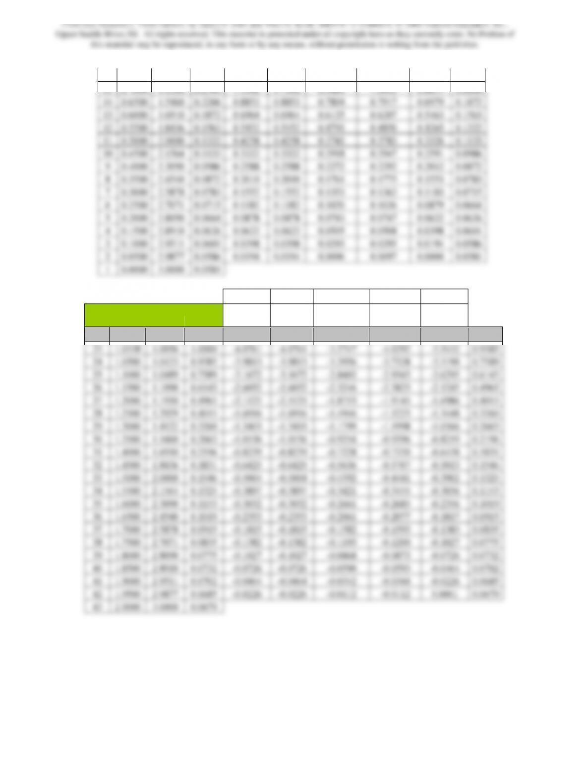
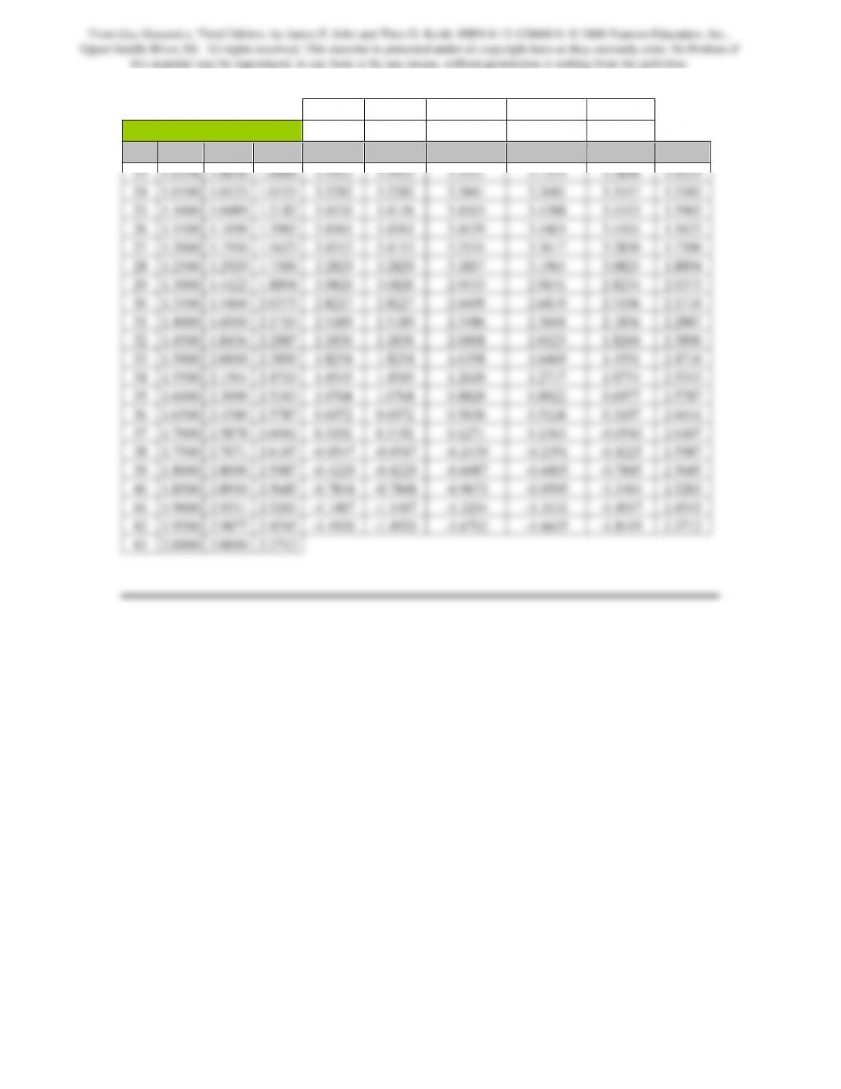
The results of the computations are contained in the following tables
x
i x
i x
i – ∆x/2 xi – ∆x/2 xi – ∆x
M
i M
i Mi – k1∆x/2 Mi – k2∆x/2 Mi – k3∆x
pt x/L Di/Dt Mi F(xi,Mi) k1 k2 k3 k4 Mi-1
From Gas Dynamics, Third Edition, by James E. John and Theo G. Keith. ISBN 0-13-120668-0. © 2006 Pearson Education, Inc.,
Upper Saddle River, NJ. All rights reserved. This material is protected under all copyright laws as they currently exist. No Portion of
this material may be reproduced, in any form or by any means, without permission in writing from the publisher.
205
16 0.7500 1.2929 0.3391 1.3905 1.3905 1.2387 1.2587 1.1192 0.2765
x
i x
i x
i + ∆x/2 xi + ∆x/2 xi + ∆x
Subsonic decelerating
flow Mi M
i Mi + k1∆x/2 Mi + k2∆x/2 Mi + k3∆x
pt x/L Di/Dt Mi F(xi,Mi) k1 k2 k3 k4 Mi+1
From Gas Dynamics, Third Edition, by James E. John and Theo G. Keith. ISBN 0-13-120668-0. © 2006 Pearson Education, Inc.,
Upper Saddle River, NJ. All rights reserved. This material is protected under all copyright laws as they currently exist. No Portion of
this material may be reproduced, in any form or by any means, without permission in writing from the publisher.
206
x xi x
i + ∆x/2 xi + ∆x/2 xi + ∆x
Supersonic accelerating flow M Mi M
i + k1∆x/2 Mi + k2∆x/2 Mi + k3∆x
pt x/L Di/Dt Mi F(xi,Mi) k1 k2 k3 k4 Mi+1
From Gas Dynamics, Third Edition, by James E. John and Theo G. Keith. ISBN 0-13-120668-0. © 2006 Pearson Education, Inc.,
Upper Saddle River, NJ. All rights reserved. This material is protected under all copyright laws as they currently exist. No Portion of
this material may be reproduced, in any form or by any means, without permission in writing from the publisher.