Chapter Nine
F
FL
LO
OW
W
W
WI
IT
TH
H
F
FR
RI
IC
CT
TI
IO
ON
N
Problem 1. – Draw the T-s diagram for the adiabatic flow of a gas with γ = 1.4 in a
constant diameter pipe with friction. The reference Mach number, M1, for the flow is 3.0.
⎭
⎩
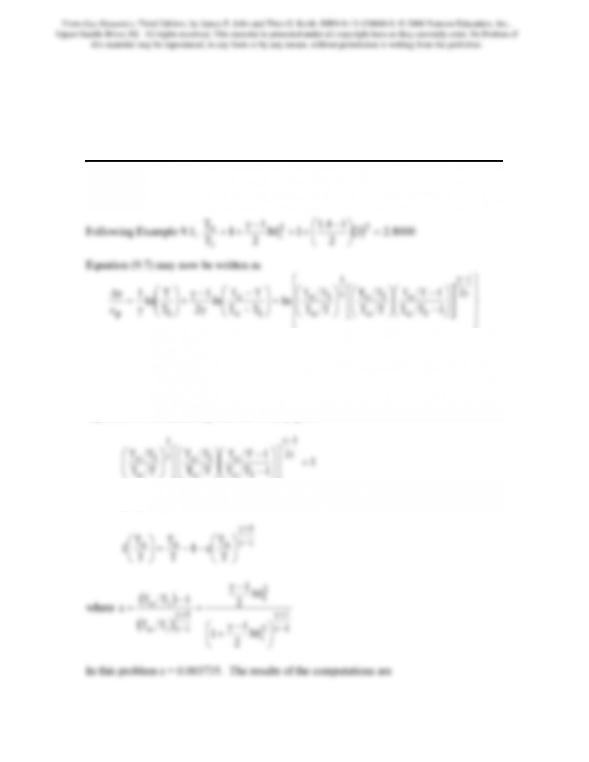
In this expression there are two values of To/T that will cause ∆s/cp to vanish. Clearly,
both will cause the argument of the natural log function to be exactly equal to 1. One
value occurs at To/T1, i.e., when T = T1. Because of the nonlinearity of the function
involving To/T, the other value must be found numerically. This is readily accomplished
using a spreadsheet program to implement the Newton-Raphson method. Setting the
argument of the natural log function to unity gives
1TT
TT
TT
1o
o
o
⎥
⎦
⎢
⎣
⎟
⎠
⎜
⎝
−
⎟
⎠
⎜
⎝
⎟
⎠
⎜
⎝
Rearranging this produces
From Gas Dynamics, Third Edition, by James E. John and Theo G. Keith. ISBN 0-13-120668-0. © 2006 Pearson Education, Inc.,
Upper Saddle River, NJ. All rights reserved. This material is protected under all copyright laws as they currently exist. No Portion of
this material may be reproduced, in any form or by any means, without permission in writing from the publisher.
170
To/T f f ′ (To/T)new Mmin
So
T=∆
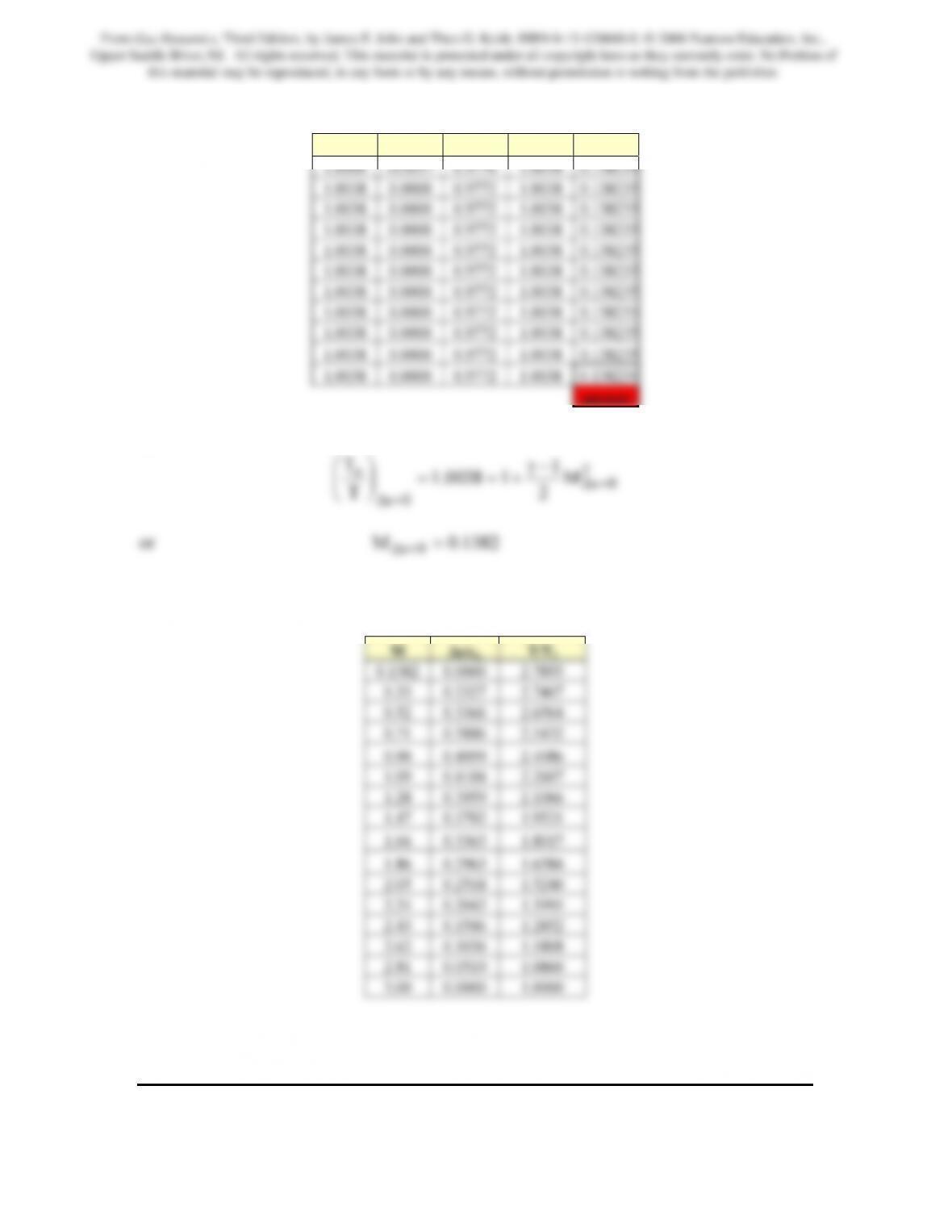
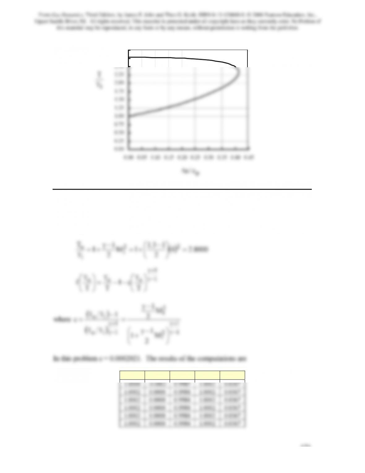
The coordinates for the Fanno-Line at this reference state are shown in the following
table. The figure shown below is a plot of this data.
From Gas Dynamics, Third Edition, by James E. John and Theo G. Keith. ISBN 0-13-120668-0. © 2006 Pearson Education, Inc.,
Upper Saddle River, NJ. All rights reserved. This material is protected under all copyright laws as they currently exist. No Portion of
this material may be reproduced, in any form or by any means, without permission in writing from the publisher.
0.00
0.25
0.50
0.75
1.00
1.25
1.50
1.75
2.00
2.25
2.50
2.75
3.00
Problem 2. – Draw the T-s diagram for the adiabatic flow of a gas with γ = 1.3 in a
constant diameter pipe with friction. The reference Mach number, M1, for the flow is 4.0.
Following the same procedure as indicated in Problem 1
To/T f df/dt (To/T)new Mmin
1
T
T
From Gas Dynamics, Third Edition, by James E. John and Theo G. Keith. ISBN 0-13-120668-0. © 2006 Pearson Education, Inc.,
Upper Saddle River, NJ. All rights reserved. This material is protected under all copyright laws as they currently exist. No Portion of
this material may be reproduced, in any form or by any means, without permission in writing from the publisher.
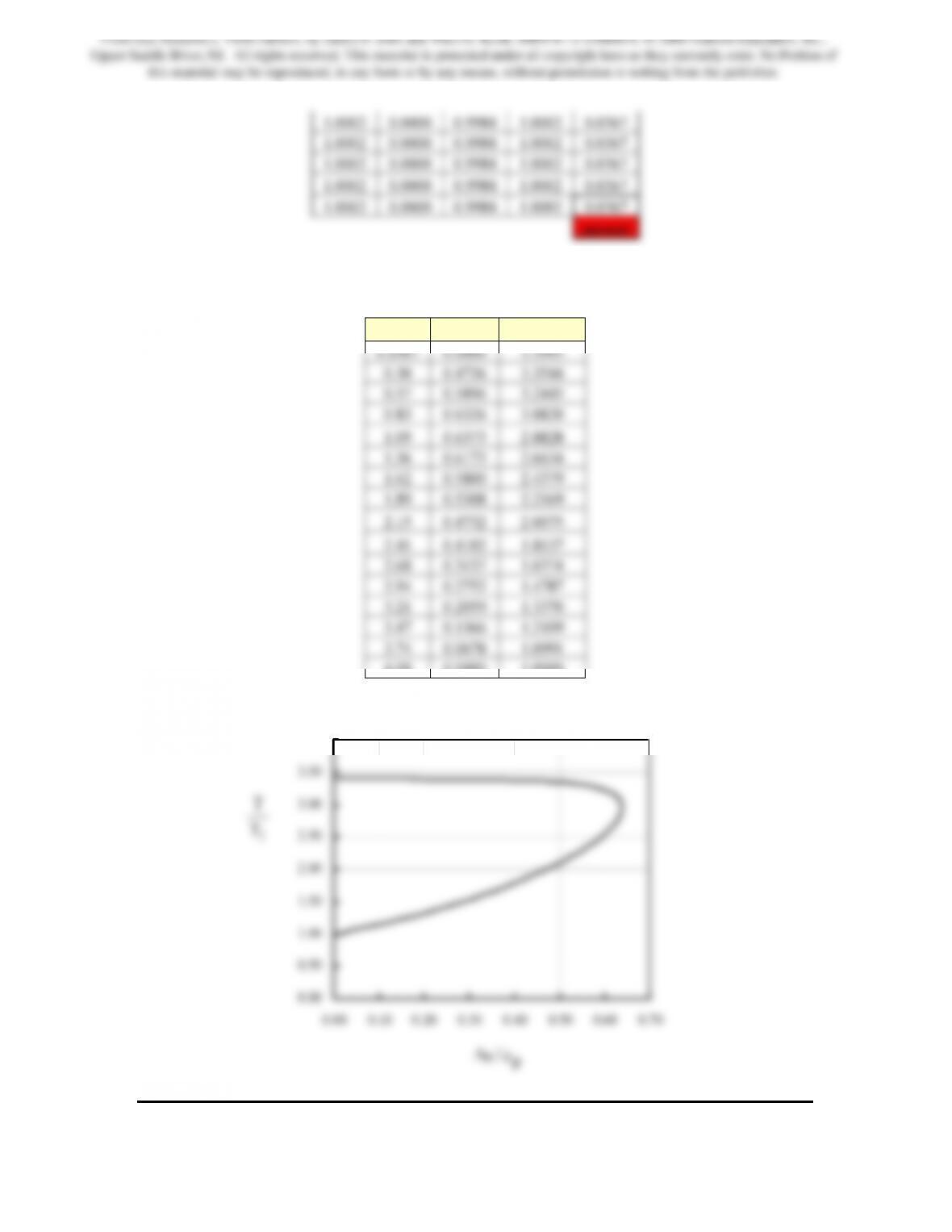
The coordinates for the Fanno-Line at this reference state are shown in the following
table. The figure shown below is a plot of this data.
M ∆s/cp T/T1
4.00 0.0000 1.0000
0.00
0.50
1.00
1.50
2.00
2.50
3.00
3.50
4.00
1
T
T
From Gas Dynamics, Third Edition, by James E. John and Theo G. Keith. ISBN 0-13-120668-0. © 2006 Pearson Education, Inc.,
Upper Saddle River, NJ. All rights reserved. This material is protected under all copyright laws as they currently exist. No Portion of
this material may be reproduced, in any form or by any means, without permission in writing from the publisher.
173
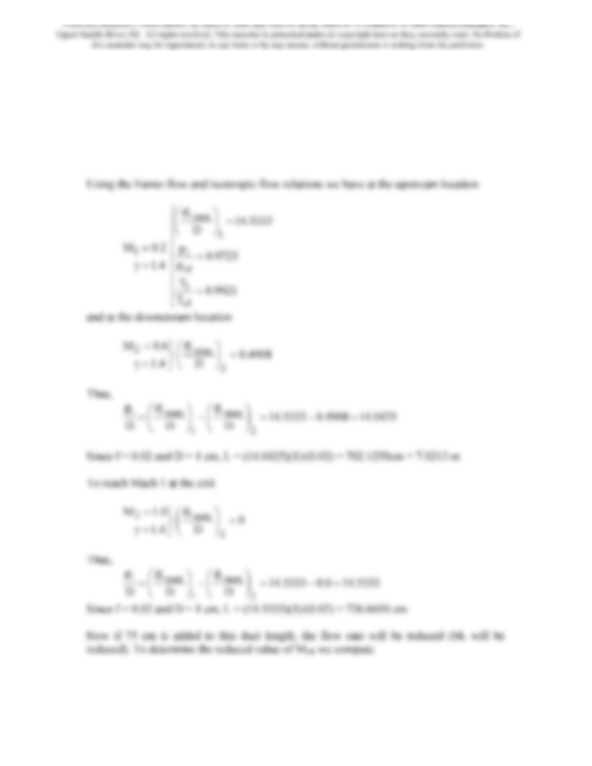
Problem 3. – Air (γ = 1.4) flows into a constant-area insulated duct with a Mach number
of 0.20. For a duct diameter of 1 cm and friction coefficient of 0.02, determine the duct
length required to reach Mach 0.60. Determine the length required to attain Mach 1.
Finally if an additional 75 cm is added to the duct length needed to reach Mach 1, while
the initial stagnation conditions are maintained, determine the reduction in flow rate that
would occur.
From Gas Dynamics, Third Edition, by James E. John and Theo G. Keith. ISBN 0-13-120668-0. © 2006 Pearson Education, Inc.,
Upper Saddle River, NJ. All rights reserved. This material is protected under all copyright laws as they currently exist. No Portion of
this material may be reproduced, in any form or by any means, without permission in writing from the publisher.
0333.16
1
1
D
R1
=
⎟
⎠
⎜
⎝
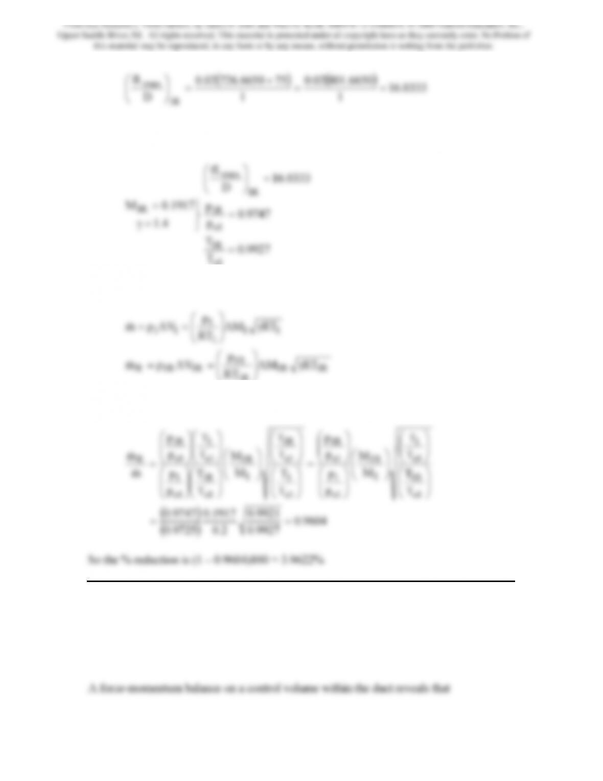
From this value we find that M1R = 0.1917. Note the subscript R has been added to
indicate the reduced value. Using the isentropic flow relations we have
⎭
⎬
⎫
=γ
=
4.1
1917.0M R1
9927.0
T
T
9747.0
p
p
0333.16
D
1o
R1
1o
R1
R1
max
=
=
=
⎟
⎠
⎜
⎝
The original mass flow rate and the reduced flow rate may be written respectively as
1R
RT
⎠
⎝
Since the stagnation conditions are maintained we may write the following
T
T
T
T
M
M
p
p
p
p
T
T
T
T
M
M
T
T
p
p
T
T
p
p
m
m
1o
R1
1o
1
1
1R
1o
1
1o
R1
1o
1
1o
R1
1
1R
1o
R1
1o
1
1o
1
1o
R1
R
⎟
⎟
⎠
⎞
⎜
⎜
⎝
⎛
⎟
⎟
⎠
⎞
⎜
⎜
⎝
⎛
⎟
⎟
⎠
⎞
⎜
⎜
⎝
⎛
⎟
⎟
⎠
⎞
⎜
⎜
⎝
⎛
⎟
⎟
⎠
⎞
⎜
⎜
⎝
⎛
=
⎟
⎟
⎠
⎞
⎜
⎜
⎝
⎛
⎟
⎟
⎠
⎞
⎜
⎜
⎝
⎛
⎟
⎟
⎠
⎞
⎜
⎜
⎝
⎛
⎟
⎟
⎠
⎞
⎜
⎜
⎝
⎛
⎟
⎟
⎠
⎞
⎜
⎜
⎝
⎛
⎟
⎟
⎠
⎞
⎜
⎜
⎝
⎛
⎟
⎟
⎠
⎞
⎜
⎜
⎝
⎛
=
&
&
Problem 4. – Air (γ = 1.4 and R = 0.287 kJ/kg · K) enters a constant-area insulated duct
with a Mach number of 0.35, a stagnation pressure of 105 kPa, and stagnation
temperature of 300 K. For a duct length of 50 cm, duct diameter of 1 cm, and friction
coefficient of 0.022, determine the air force on the duct wall.
From Gas Dynamics, Third Edition, by James E. John and Theo G. Keith. ISBN 0-13-120668-0. © 2006 Pearson Education, Inc.,
Upper Saddle River, NJ. All rights reserved. This material is protected under all copyright laws as they currently exist. No Portion of
this material may be reproduced, in any form or by any means, without permission in writing from the publisher.
12airon wall2211 VVmFApAp
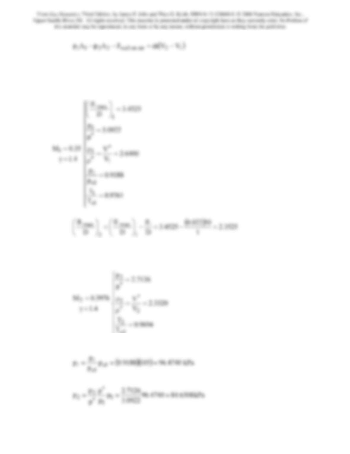
Thus to compute the force we must first determine the entry and exit values of the static
pressure and velocity as well as the mass flow rate.
Using the Fanno flow and isentropic flow relations we have at the upstream location
35.0M1
=
⎪
⎪
⎪
⎪
⎪
⎪
⎪
⎨
⎧
==
ρ
=
=
⎟
⎠
⎞
⎜
⎝
⎛
∗
∗
∗
6400.2
V
0922.3
p
p
4525.3
D
fL
1
1
1
max
3525.2
1
4525.3
D
D
D
1
2
⎟
⎠
⎜
⎝
=
⎟
⎠
⎜
⎝
From this value we find that M2 = 0.3976. Using the Fanno and isentropic flow relations
we have
⎪
⎪
⎪
⎩
=
9694.0
T
T
2o
2
Since po1 = 105 kPa,
p
1
From Gas Dynamics, Third Edition, by James E. John and Theo G. Keith. ISBN 0-13-120668-0. © 2006 Pearson Education, Inc.,
Upper Saddle River, NJ. All rights reserved. This material is protected under all copyright laws as they currently exist. No Portion of
this material may be reproduced, in any form or by any means, without permission in writing from the publisher.
176
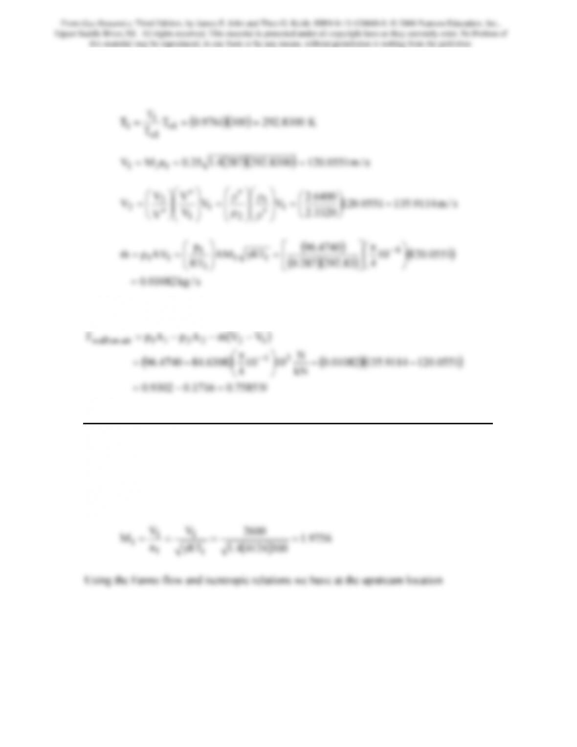
Because the flow is adiabatic: To1 = To2 = 300 K.
s/kg01082.0
1
=
⎦
⎣
⎠
⎝
Finally,
N7585.01716.09302.0
kN
4
=−=
⎠
⎝
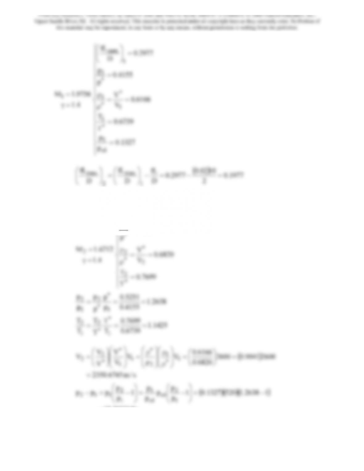
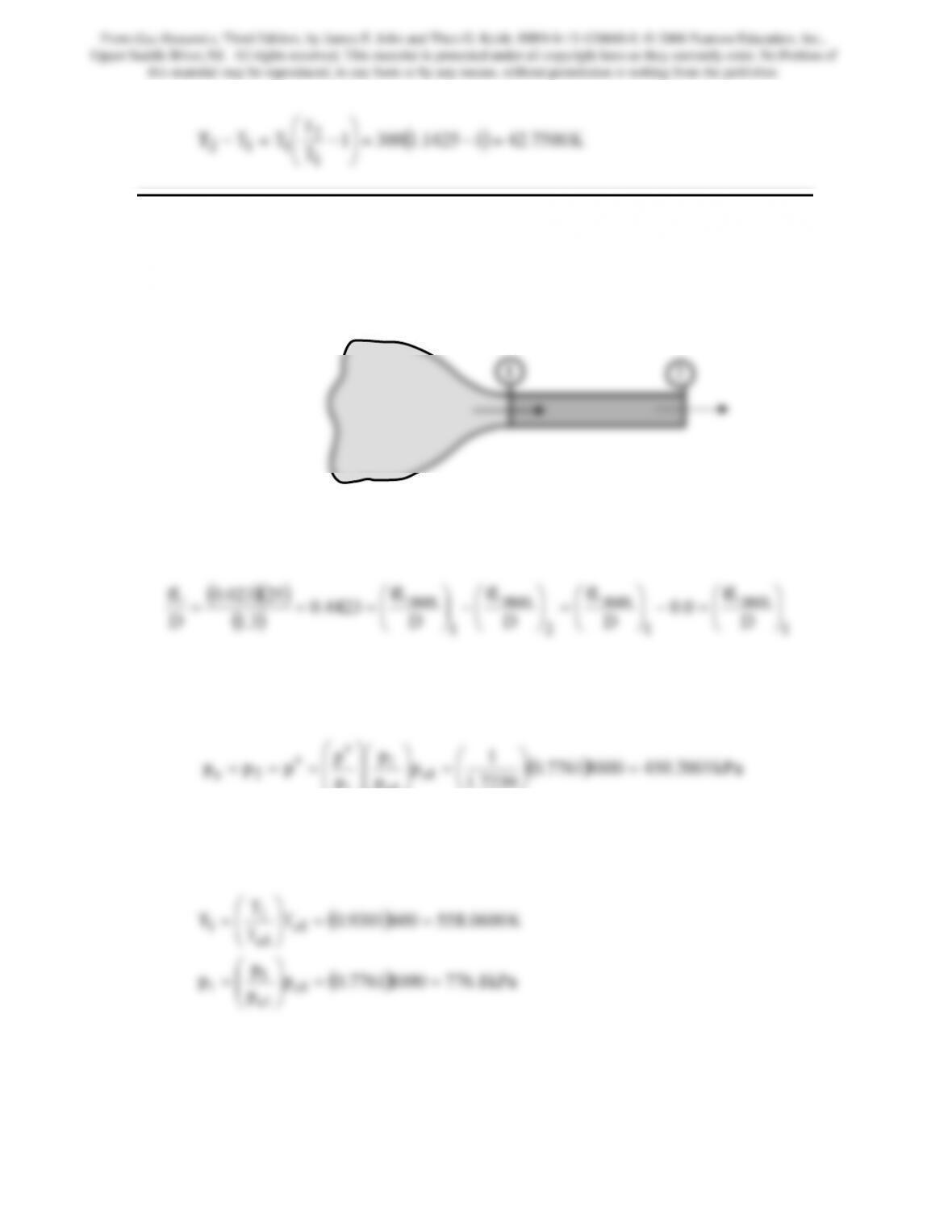
Problem 5. – Hydrogen (γ = 1.4 and R = 4124 J/kg · K) enters a constant-area insulated
duct with a velocity of 2600 m/s, static temperature of 300 K, and stagnation pressure of
520 kPa. The duct is 2 cm in diameter, and 10 cm long. For a friction coefficient of 0.02,
determine the change of static pressure and temperature in the duct and the exit velocity
of the hydrogen.
From Gas Dynamics, Third Edition, by James E. John and Theo G. Keith. ISBN 0-13-120668-0. © 2006 Pearson Education, Inc.,
Upper Saddle River, NJ. All rights reserved. This material is protected under all copyright laws as they currently exist. No Portion of
this material may be reproduced, in any form or by any means, without permission in writing from the publisher.
9756.1M1
=
⎪
⎪
⎪
⎪
⎪
⎪
⎪
⎨
⎧
==
ρ
=
=
⎟
⎠
⎞
⎜
⎝
⎛
∗
∗
∗
6166.0
V
4155.0
p
p
2977.0
D
fL
1
1
1
max
1977.0
2
2977.0
D
D
D
1
2
⎟
⎠
⎜
⎝
=
⎟
⎠
⎜
⎝
From this value we find that M2 = 1.6712. Using the Fanno and isentropic flow relations
we have
6712.1M2
=
⎪
⎪
⎪
⎪
⎧
ρ
=
∗
∗
V
5251.0
p
2
2
From Gas Dynamics, Third Edition, by James E. John and Theo G. Keith. ISBN 0-13-120668-0. © 2006 Pearson Education, Inc.,
Upper Saddle River, NJ. All rights reserved. This material is protected under all copyright laws as they currently exist. No Portion of
this material may be reproduced, in any form or by any means, without permission in writing from the publisher.
T
2
⎞
⎛−=−
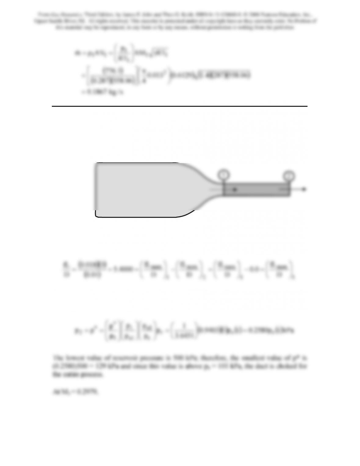
Problem 6. – A constant-area duct, 25 cm in length by 1.3 cm in diameter, is connected
to an air reservoir through a converging nozzle, as shown in Figure P9.6. For a constant
reservoir pressure of 1 MPa and constant reservoir temperature of 600 K, determine the
flow rate through the duct for a back pressure of 101 kPa. Assume adiabatic flow in the
tube with f = 0.023.
Figure P9.6
First determine the exit pressure assuming the duct is choked. Therefore,
()
1
1
2
1
D
D
D
D
3.1
D
⎠
⎝
⎠
⎝
⎠
⎝
⎠
⎝
From this value we can determine that M1 = 0.6129. At this Mach number using the
isentropic and Fanno flow pressure relations we may write that
7239.1
p
p
1o
1
⎠
⎝
⎟
⎠
⎜
⎝
⎟
⎠
⎜
⎝
Since the back pressure is well below this value the assumption that the duct is choked is
correct and we may proceed to determine the flow rate. Now at M1 = 0.6129,
From Gas Dynamics, Third Edition, by James E. John and Theo G. Keith. ISBN 0-13-120668-0. © 2006 Pearson Education, Inc.,
Upper Saddle River, NJ. All rights reserved. This material is protected under all copyright laws as they currently exist. No Portion of
this material may be reproduced, in any form or by any means, without permission in writing from the publisher.
()
()( ) ()()()()
s/kg1867.0
406.558287.0
1.776
RTAM
RT
p
AVρm
2
11
1
1
11
=
⎠
⎞
⎝
⎛π
⎥
⎦
⎤
⎢
⎣
⎡
γ
⎟
⎟
⎠
⎞
⎜
⎜
⎝
⎛
==
&
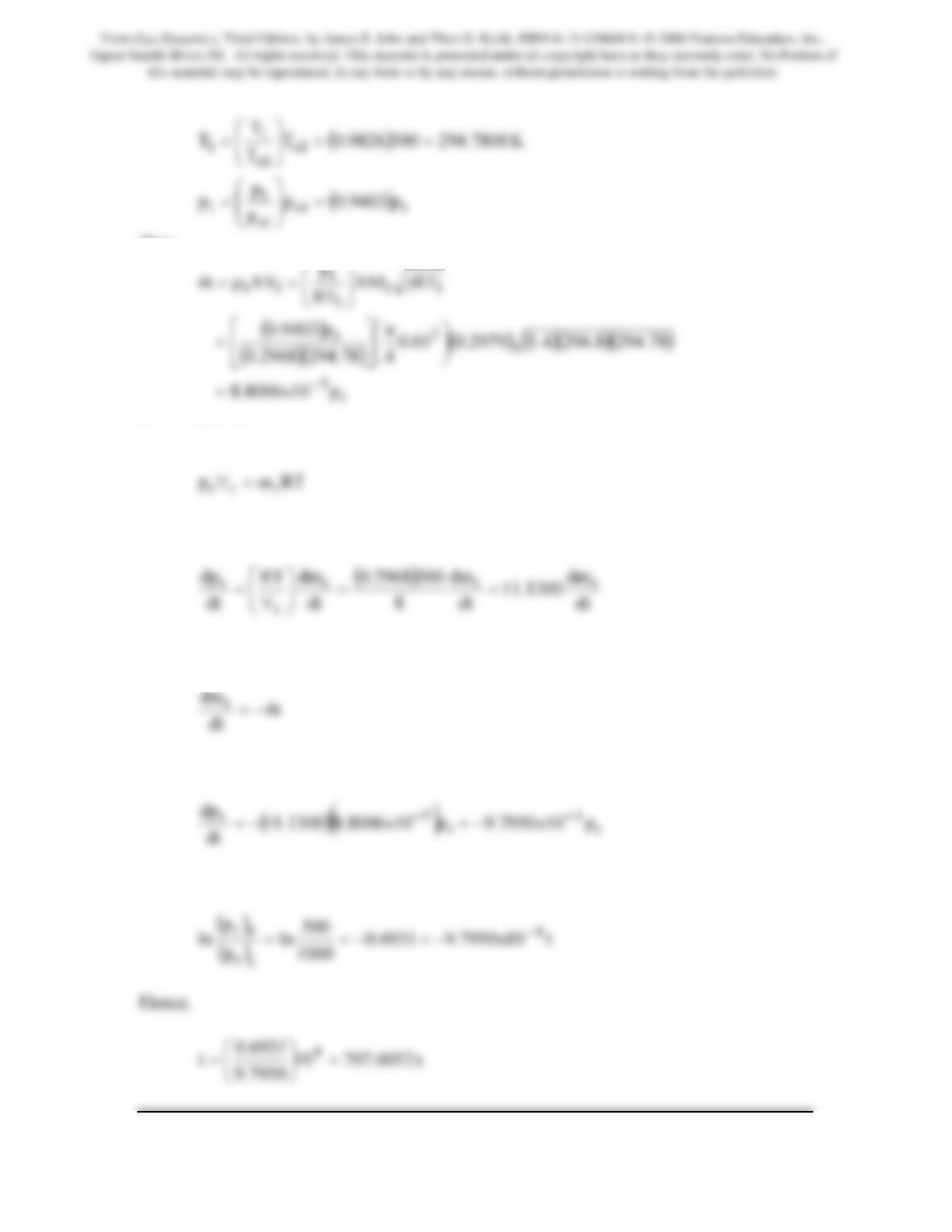
Problem 7. – Find the time required for the pressure in the tank filled with Nitrogen
(γ = 1.4 and R = 296.8 J/kg · K) shown in Figure P9.7 to drop from 1 MPa to 500 kPa.
The tank volume is 8 m3 and the tank temperature is 300K. Assume the tank temperature
remains constant and the flow in the 3 m long, 1 cm diameter connecting tube is adiabatic
with f = 0.018. The back pressure is 101 kPa.
Figure P9.7
First determine the exit pressure assuming the duct is choked. Therefore,
From this value we can determine that M1 = 0.2979. At this Mach number using the
isentropic and Fanno flow pressure relations we may write that
From Gas Dynamics, Third Edition, by James E. John and Theo G. Keith. ISBN 0-13-120668-0. © 2006 Pearson Education, Inc.,
Upper Saddle River, NJ. All rights reserved. This material is protected under all copyright laws as they currently exist. No Portion of
this material may be reproduced, in any form or by any means, without permission in writing from the publisher.
()
()
r1o
1o
1
1
1o
1o
1
1
p9403.0p
p
p
p
K7800.2943009826.0T
T
T
T
=
⎟
⎟
⎠
⎞
⎜
⎜
⎝
⎛
=
==
⎟
⎟
⎠
⎞
⎜
⎜
⎝
⎛
=
Thus,
()
2
r
11
1
1
11
p9403.0
RTAM
RT
p
AVρm
⎞
⎛π
⎤
⎡
γ
⎟
⎟
⎠
⎞
⎜
⎜
⎝
⎛
==
&
Now within the reservoir,
r
r
r
Taking the time derivative of this expression gives
dt
dt
8
dt
dt
r
⎟
⎠
⎜
⎝
∀
From a mass balance on the reservoir,
dt
dmr&
Therefore,
()
()
r
r
rp10x7950.9p10x8006.81300.11
dt
Integration gives
From Gas Dynamics, Third Edition, by James E. John and Theo G. Keith. ISBN 0-13-120668-0. © 2006 Pearson Education, Inc.,
Upper Saddle River, NJ. All rights reserved. This material is protected under all copyright laws as they currently exist. No Portion of
this material may be reproduced, in any form or by any means, without permission in writing from the publisher.
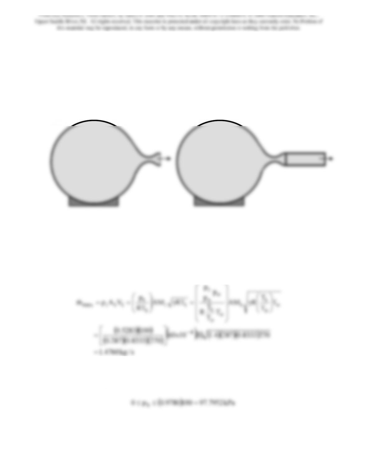
Problem 8. – A converging-diverging nozzle has an area ratio of 3.3, i.e., the exit and
therefore the duct area is 3.3 times the throat area, which is 60 cm2. The nozzle is
supplied from a tank containing air (γ = 1.4 and R = 0.287 kJ/kg · K) at 100 kPa at 270 K.
For case A of Figure P9.8, find the maximum mass flow possible through the nozzle and
the range of back pressures over which the mass flow can be attained. Repeat for case B,
in which a constant-area insulated duct of length 1.5 m and f = 0.022 is added to the
nozzle.
Case A Case B
Figure P9.8
Case A
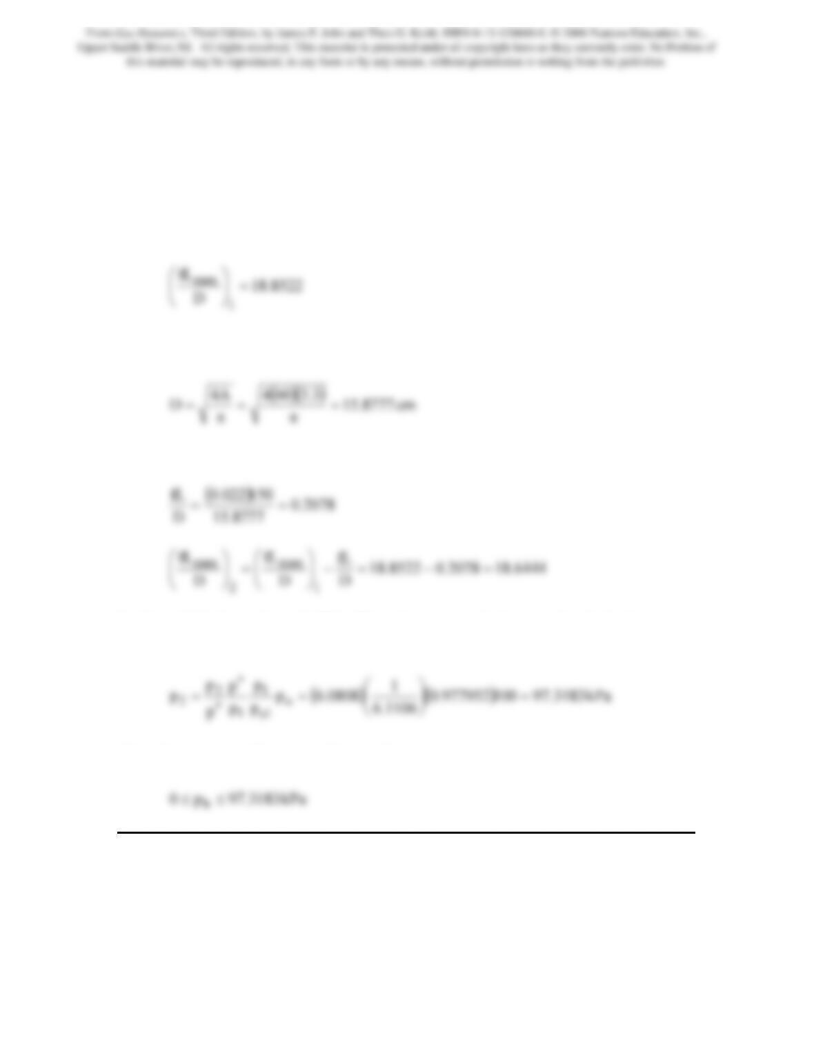
The maximum flow rate will occur when the throat Mach number is 1. At this Mach
number, the throat static to total pressure and temperature ratios are: 0.5283 and 0.8333,
respectively. Accordingly, the flow rate is computed to be
()( )()
s/kg4760.1
2708333.0287.0
T
T
T
RAM
T
T
T
R
p
p
p
RTAM
RT
p
VAρm
o
o
t
t
o
o
t
o
o
t
tt
t
t
tttmax
=
⎥
⎦
⎢
⎣
⎟
⎟
⎠
⎞
⎜
⎜
⎝
⎛
γ
⎟
⎟
⎟
⎟
⎠
⎞
⎜
⎜
⎜
⎜
⎝
⎛
=γ
⎟
⎟
⎠
⎞
⎜
⎜
⎝
⎛
==
&
For A/A* = 3.3, we can determine that the exit Mach number is 0.1787. At this value the
exit static to total pressure ratio is 0.9780. Thus, the maximum flow rate will occur for
From Gas Dynamics, Third Edition, by James E. John and Theo G. Keith. ISBN 0-13-120668-0. © 2006 Pearson Education, Inc.,
Upper Saddle River, NJ. All rights reserved. This material is protected under all copyright laws as they currently exist. No Portion of
this material may be reproduced, in any form or by any means, without permission in writing from the publisher.
182
Case B
Here too, the maximum flow rate will occur when the throat Mach number is 1. At this
Mach number, the throat static to total pressure and temperature ratios are: 0.5283 and
0.8333, respectively. Accordingly, the maximum flow rate will be the same as that in
Case A, viz., 1.4760 kg/s.
Now for subsonic flow at the nozzle exit, and the duct inlet, M1 = 0.1787.
8522.18
D
1
⎟
⎠
⎜
⎝
The diameter of the duct is computed as follows
π
π
Thus
So the exit Mach number is 0.1796. The exit pressure which is equal to the back pressure
is computed as follows
Thus, the maximum flow rate will occur for
Problem 9. – A 3-m3 volume tank, R, is to be filled to a pressure of 200 kPa (initial
pressure 0 kPa). The tank is connected to a reservoir tank, L, containing air at 3 MPa and
300 K, whose volume is also 3 m3. A 30-m length of 2.5 cm-diameter tubing is used to
connect the two vessels, as shown in Figure P9.9. Determine the time required to fill the
tank to 200 kPa. Assume Fanno flow with f = 0.02.
From Gas Dynamics, Third Edition, by James E. John and Theo G. Keith. ISBN 0-13-120668-0. © 2006 Pearson Education, Inc.,
Upper Saddle River, NJ. All rights reserved. This material is protected under all copyright laws as they currently exist. No Portion of
this material may be reproduced, in any form or by any means, without permission in writing from the publisher.
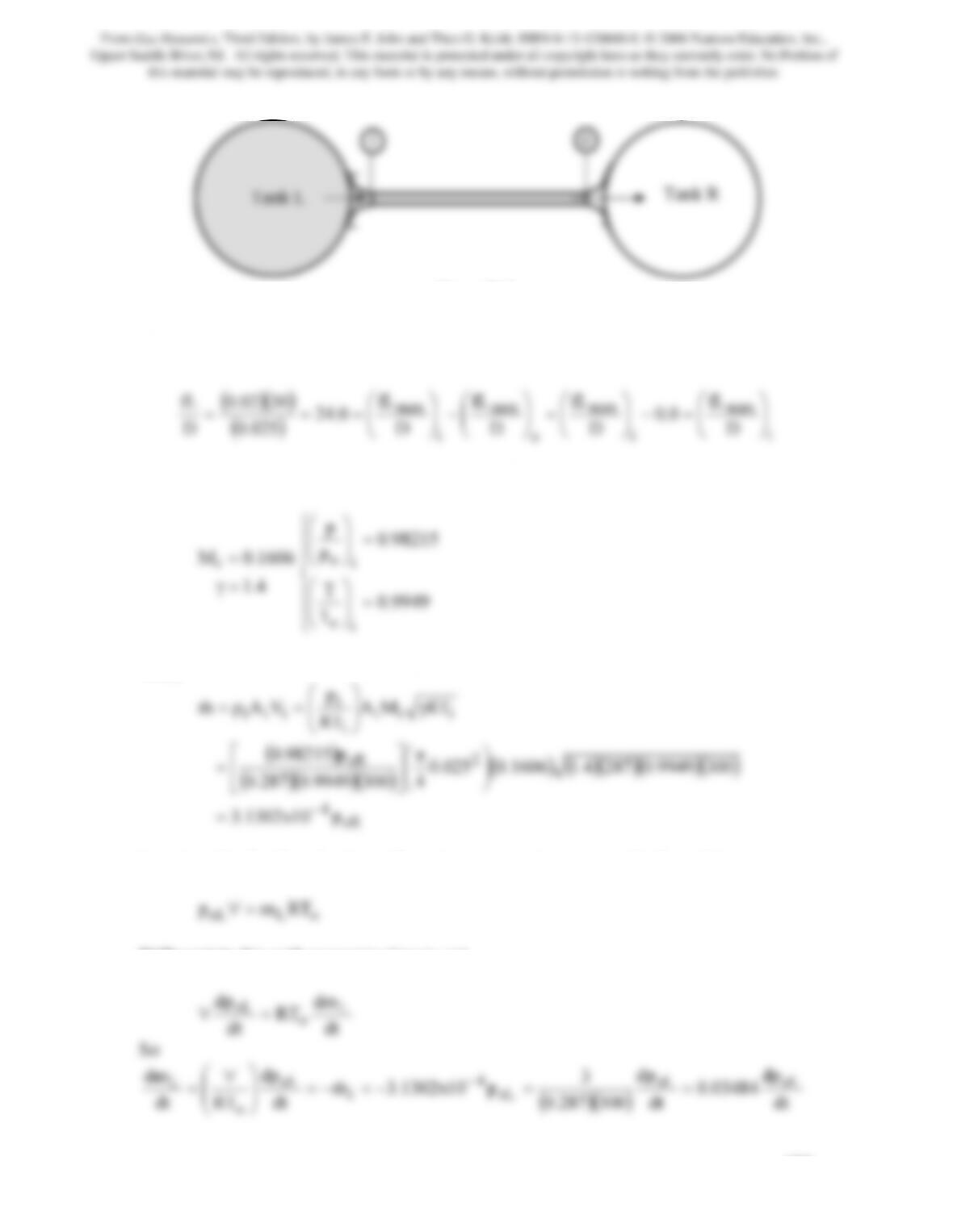
Figure P9.9
Because R, the tank on the right, is evacuated, it may be safely assumed that Me = 1.
Therefore,
()
i
i
e
i
D
D
D
D
025.0
D
⎠
⎝
⎠
⎝
⎠
⎝
⎠
⎝
From this value we find that Mi = 0.1606. Using the isentropic flow relations we have
4.1
=γ
⎪
⎪
⎩
⎨
=
⎟
⎟
⎠
⎞
⎜
⎜
⎝
⎛
9949.0
T
T
i
o
Thus,
()
2
oR
iii
i
i
iii
p98215.0
RTMA
RT
p
VAρm
⎞
⎛π
⎤
⎡
γ
⎟
⎟
⎠
⎞
⎜
⎜
⎝
⎛
==
&
Now in order that there be Fanno flow, To must remain constant. So for tank L
Differentiate this with respect to time to get
From Gas Dynamics, Third Edition, by James E. John and Theo G. Keith. ISBN 0-13-120668-0. © 2006 Pearson Education, Inc.,
Upper Saddle River, NJ. All rights reserved. This material is protected under all copyright laws as they currently exist. No Portion of
this material may be reproduced, in any form or by any means, without permission in writing from the publisher.
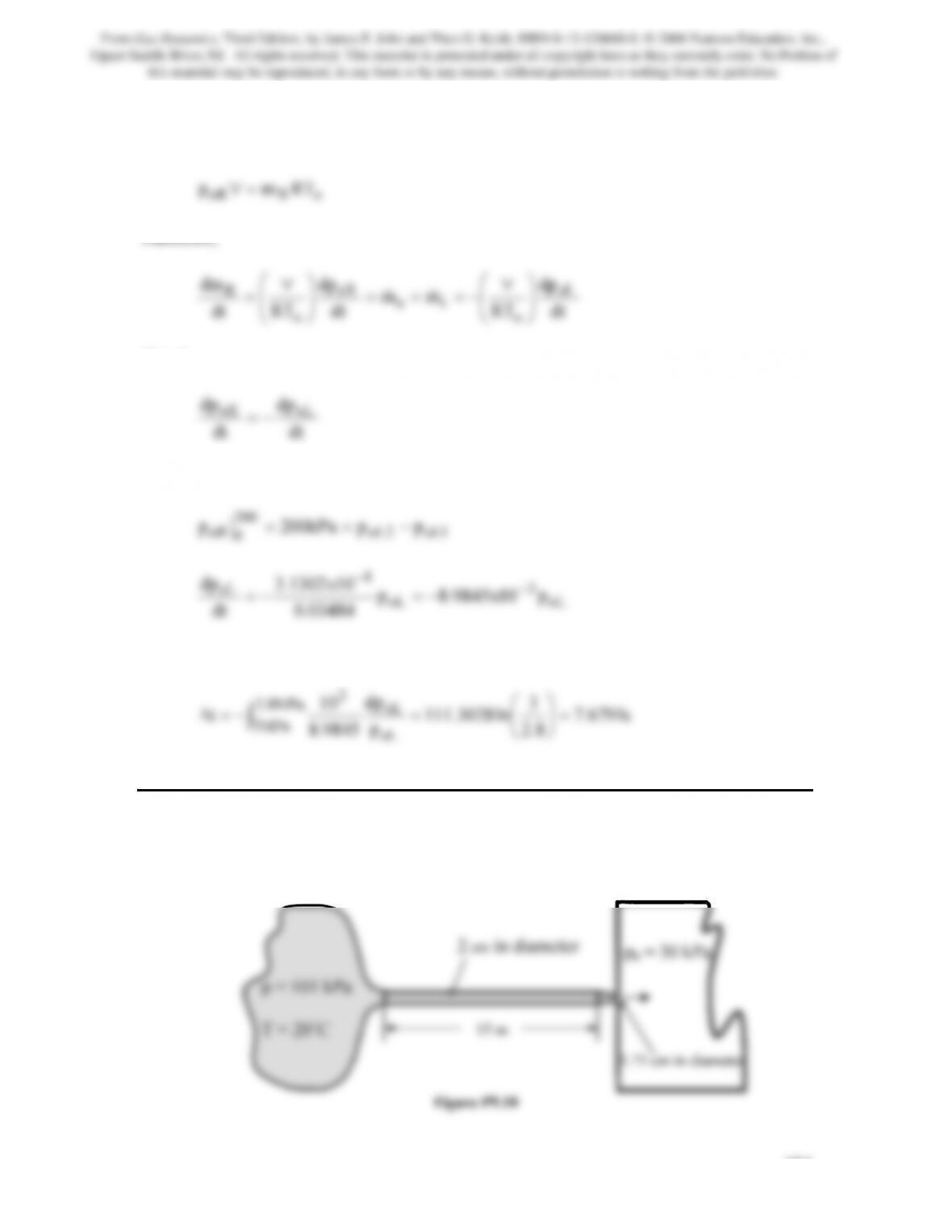
Similarly, for the tank on the right
Therefore,
Clearly,
dt
dt
That is
oL
3
oL
oL p10x9845.8p
03484.0
10x1302.3
dt
dp −
Integration brings
3
dp
10
oL
MPa8.2
3=
⎞
⎛
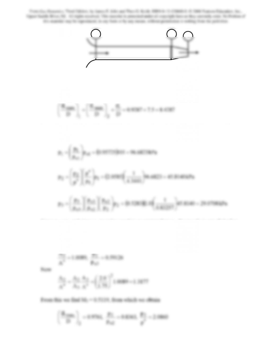
Problem 10. Find the mass flow rate of air (γ = 1.4 and R = 0.287 kJ/kg · K) through the
system shown in Figure P9.10. Assume Fanno line flow in the duct and isentropic flow in
the converging sections; f = 0.01.
From Gas Dynamics, Third Edition, by James E. John and Theo G. Keith. ISBN 0-13-120668-0. © 2006 Pearson Education, Inc.,
Upper Saddle River, NJ. All rights reserved. This material is protected under all copyright laws as they currently exist. No Portion of
this material may be reproduced, in any form or by any means, without permission in writing from the publisher.
1 2
From Gas Dynamics, Third Edition, by James E. John and Theo G. Keith. ISBN 0-13-120668-0. © 2006 Pearson Education, Inc.,
Upper Saddle River, NJ. All rights reserved. This material is protected under all copyright laws as they currently exist. No Portion of
this material may be reproduced, in any form or by any means, without permission in writing from the publisher.
4761.85.79761.0
D
fL
D
fL
D
fL
2
max
1
max =+=+
⎟
⎠
⎞
⎜
⎝
⎛
=
⎟
⎠
⎞
⎜
⎝
⎛
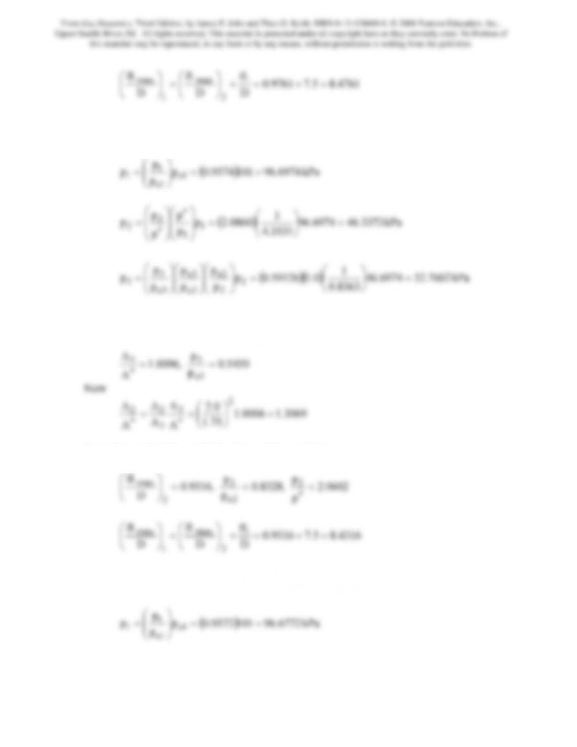
From this, we find that M1 = 0.2501. Consequently, with M1, M2 and M3 we are able to
compute the following static pressures
p
1
⎞
⎛
8363.0
p
p
p
2
2o
3o
3=
⎠
⎝
⎟
⎠
⎜
⎝
⎟
⎠
⎜
⎝
⎟
⎠
⎜
⎝
Too large; therefore M3 needs to be increased. After a few tries M3 = 0.973 and from the
isentropic relations we find
p
A
33 ==
From this we find M2 = 0.5180, from which we obtain
p
p
fL 2
2
max ===
⎞
⎛
4316.85.79316.0
D
D
D
2
1
⎟
⎠
⎜
⎝
=
⎟
⎠
⎜
⎝
From this, we find that M1 = 0.2506. Consequently, with M1, M2 and M3 we are able to
compute the following static pressures
From Gas Dynamics, Third Edition, by James E. John and Theo G. Keith. ISBN 0-13-120668-0. © 2006 Pearson Education, Inc.,
Upper Saddle River, NJ. All rights reserved. This material is protected under all copyright laws as they currently exist. No Portion of
this material may be reproduced, in any form or by any means, without permission in writing from the publisher.
1
p
p
2
⎞
⎛
⎟
⎞
⎜
⎛
⎟
⎞
⎜
⎛
8328.0
p
p
p
2
2o
3o
3=
⎠
⎝
⎟
⎠
⎜
⎝
⎟
⎠
⎜
⎝
⎟
⎠
⎜
⎝
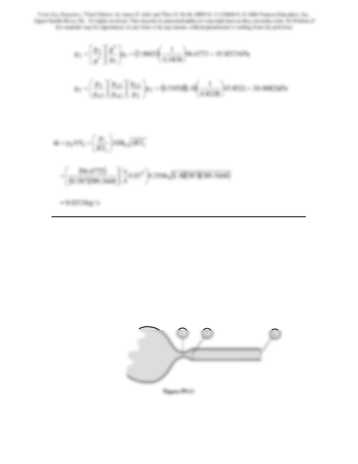
Slightly too high but close enough. Note from the isentropic relations at M1, (T/To)1 =
(0.9876)293 = 289.3668K
() ()( )( )
s/kg0313.0
43668.289287.0
RTAM
RT
p
AVρm
11
1
1
11
=
⎠
⎝
⎥
⎦
⎢
⎣
γ
⎟
⎟
⎠
⎞
⎜
⎜
⎝
⎛
==
&
Problem 11. – For the flow of air (γ = 1.4 and R = 0.287 kJ/kg · K) from the reservoir at
650 kPa and 1000 K shown in Figure P9.11, assume isentropic flow in the convergent-
divergent nozzle and Fanno flow in the constant-area duct, which has a length of 20 cm
and a diameter of 1 cm. The area ratio A2/A1 of the C-D nozzle is 2.9. Take the friction
factor to be 0.02.
(a) Find the mass flow rate for a back pressure of 0 kPa.
(b) For part (a), find the pressure at the exit plane of the duct.
(c) Find the back pressure necessary for a normal shock to occur at the exit plane
of the nozzle (2).
(d) Find the back pressure necessary for a normal shock to appear just
downstream of the nozzle throat (1).
1 2 e
From Gas Dynamics, Third Edition, by James E. John and Theo G. Keith. ISBN 0-13-120668-0. © 2006 Pearson Education, Inc.,
Upper Saddle River, NJ. All rights reserved. This material is protected under all copyright laws as they currently exist. No Portion of
this material may be reproduced, in any form or by any means, without permission in writing from the publisher.