Chapter Seven
P
PR
RA
AN
ND
DT
TL
L–
–M
ME
EY
YE
ER
R
F
FL
LO
OW
W
Problem 1. – Use a trigonometric development to demonstrate that for an expansion flow
around a convex corner, Vn2 > Vn1 (see Figure 7.2 in Section 7.2).
From Gas Dynamics, Third Edition, by James E. John and Theo G. Keith. ISBN 0-13-120668-0. © 2006 Pearson Education, Inc.,
Upper Saddle River, NJ. All rights reserved. This material is protected under all copyright laws as they currently exist. No Portion of
this material may be reproduced, in any form or by any means, without permission in writing from the publisher.
Using the solver developed in Example 7.1, we obtain
20º
From Gas Dynamics, Third Edition, by James E. John and Theo G. Keith. ISBN 0-13-120668-0. © 2006 Pearson Education, Inc.,
Upper Saddle River, NJ. All rights reserved. This material is protected under all copyright laws as they currently exist. No Portion of
this material may be reproduced, in any form or by any means, without permission in writing from the publisher.
131
()
()()
[]
()
dx
x1
1
x11
x2
x1
xdx
x1
2
1
1
x
d– 22
2
2
2+−γ++γ
=
+
+
−γ
+
=α
Next use partial fractions to divide the right hand side into two groups of terms
x2
B
A
22
2
22 +−γ++γ
=
+
()
0B1A
=+γ+
Solving this pair yields: A = γ + 1 and B = −1. Thus, the transformed equation can be
arranged into two groups and leads to the following two integrals:
()
()
∫∫
∫∫∫
+
−
+γ
−γ
+
−=
−
+γ
−=
⎟
⎟
⎞
⎜
⎜
⎛
−γ
−
−
dx
)x1(
1
dx
]x
1
1
1[
1
dx
1
dx
1
dM
1
1M
2
2
22
2
Making use of the given integral identity we get
⎠
⎝
2
Problem 4. – A reservoir containing air (γ = 1.4) at 2 MPa is connected to ambient air at
101 kPa through a converging-diverging nozzle designed to produce flow at Mach 2.0,
with axial flow at the nozzle exit plane (Figure P7.4). Under these conditions, the nozzle
is underexpanded, with a Prandtl Meyer expansion fan at the exit. Find the flow direction
after the initial expansion fan. How does this turning angle affect the net axial thrust
forces exerted by the fluid on the nozzle?
From Gas Dynamics, Third Edition, by James E. John and Theo G. Keith. ISBN 0-13-120668-0. © 2006 Pearson Education, Inc.,
Upper Saddle River, NJ. All rights reserved. This material is protected under all copyright laws as they currently exist. No Portion of
this material may be reproduced, in any form or by any means, without permission in writing from the publisher.
132
Figure P7.4
At °=ν== 3798.26,1278.0
p
,0.2M 1
1
1
101
p
2
The turning does not affect thrust, because the expansion occurs outside nozzle.
Problem 5. – Develop a computer program that will yield values of ν and µ versus M for
Prandtl-Meyer flow for γ = 1.3 over the range M = 1.0 to M = 2.5, using Mach number
increments of 0.1.
A table of the Prandtl-Meyer function and wave
angle versus Mach number for γ = 1.3
M ν (rad) ν (deg) µ (rad) µ (deg)
α = ?
2 MPa
From Gas Dynamics, Third Edition, by James E. John and Theo G. Keith. ISBN 0-13-120668-0. © 2006 Pearson Education, Inc.,
Upper Saddle River, NJ. All rights reserved. This material is protected under all copyright laws as they currently exist. No Portion of
this material may be reproduced, in any form or by any means, without permission in writing from the publisher.
133
Problem 6. – A uniform supersonic flow of a perfect gas with γ = 1.3 and Mach number
3.0 expands around a 5° convex corner. Determine the downstream Mach number, ratio
of downstream to upstream velocity, and ratio of downstream to upstream stagnation
temperature.
T
1=
4255.0
00.3
T
M
a
M
v
T
1
1
1
1
1
o1
⎟
⎠
⎜
⎝
⎟
⎠
⎜
⎝
⎟
⎠
⎜
⎝
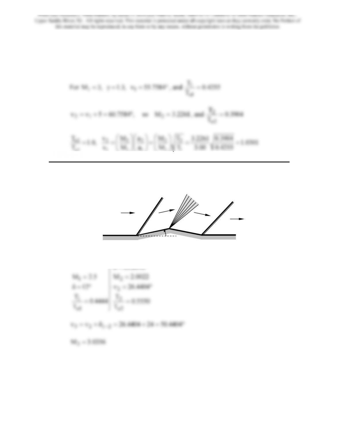
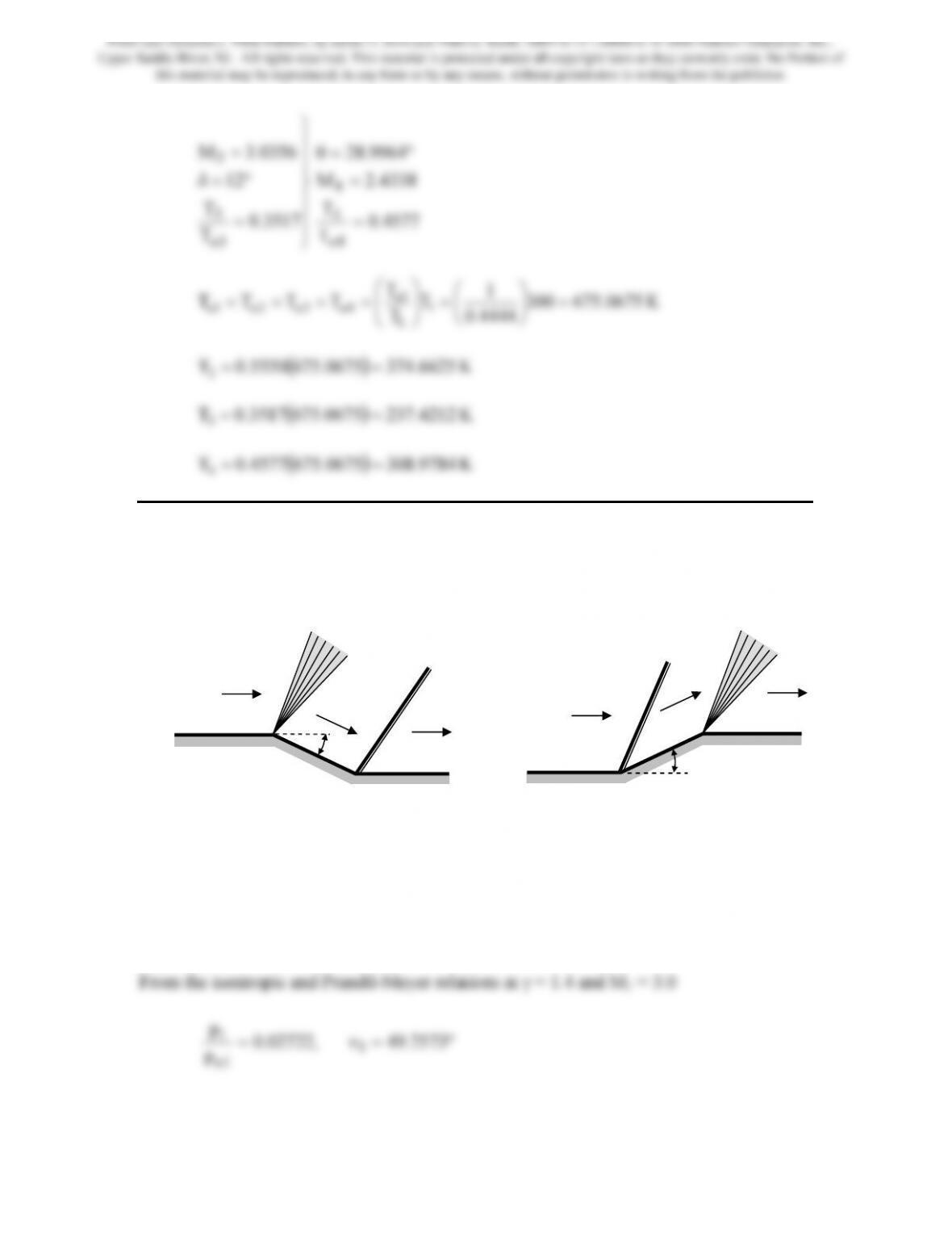
Problem 7. – For flow at Mach 2.5 and γ = 1.4 over the symmetrical protrusion shown in
Figure P7.5, find M2, M3, M4, T2, T3, and T4.
Figure P7.7
⎪
⎪
⎪
⎫
=
5.2M
1
0022.2M
8016.33
2
=
°=θ
T1 = 300 K
12°
M1 = 2.5 M3
M2M4
From Gas Dynamics, Third Edition, by James E. John and Theo G. Keith. ISBN 0-13-120668-0. © 2006 Pearson Education, Inc.,
Upper Saddle River, NJ. All rights reserved. This material is protected under all copyright laws as they currently exist. No Portion of
this material may be reproduced, in any form or by any means, without permission in writing from the publisher.
134
⎪
⎪
⎪
⎫
=
0356.3M
3
9964.28
°=θ
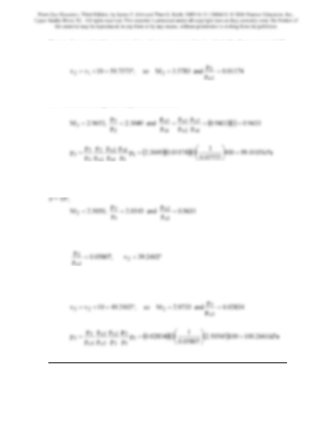
Problem 8. – A uniform supersonic flow of a perfect gas with γ = 1.4, Mach number 3.0
and an upstream static pressure of 100kPa flows over a geometry as shown in P7.8.
Determine the downstream static pressure for both profiles.
(a) Expansion Fan-Oblique Shock Geometry (b) Oblique Shock- Expansion Fan Geometry
Figure P7.8
Divide the flow field of both cases shown in Figure P7.8 into 3 regions of uniform flow
with region 1 on the left and region 3 on the right.
Case (a)
p1 = 100 kPa
10°
M1 = 3
M3
M2
α1 = 0°
α
3 = 0°
p1 = 100 kPa
10°
M1 = 3 M3
M2
α
3 = 0°
α
1 = 0°
From Gas Dynamics, Third Edition, by James E. John and Theo G. Keith. ISBN 0-13-120668-0. © 2006 Pearson Education, Inc.,
Upper Saddle River, NJ. All rights reserved. This material is protected under all copyright laws as they currently exist. No Portion of
this material may be reproduced, in any form or by any means, without permission in writing from the publisher.
135
Region 2 is reached by passing through an expansion fan in which the flow is turned 10º.
Therefore,
p
p
2o
2
Region 3 is reached by passing through an oblique shock in which the flow is turned back
10º. Therefore, using the oblique shock relations
02722.0
p
p
p
p
1
1o
2o
2
3=
⎠
⎝
Case (b)
Region 2 is reached by passing through an oblique shock in which the flow is turned
through 10º. Therefore, using the oblique shock relations with γ = 1.4, M1 = 3.0 and
p
p
1o
1
From the isentropic and Prandtl-Meyer relations at γ = 1.4 and M2 = 2.5050
°=ν= 2402.39,05807.0
p
2
o2
Region 3 is reached by passing through an expansion fan in which the flow is turned 10º.
Therefore,
Problem 9. – A two-dimensional, flat plate is inclined at a positive angle of attack in a
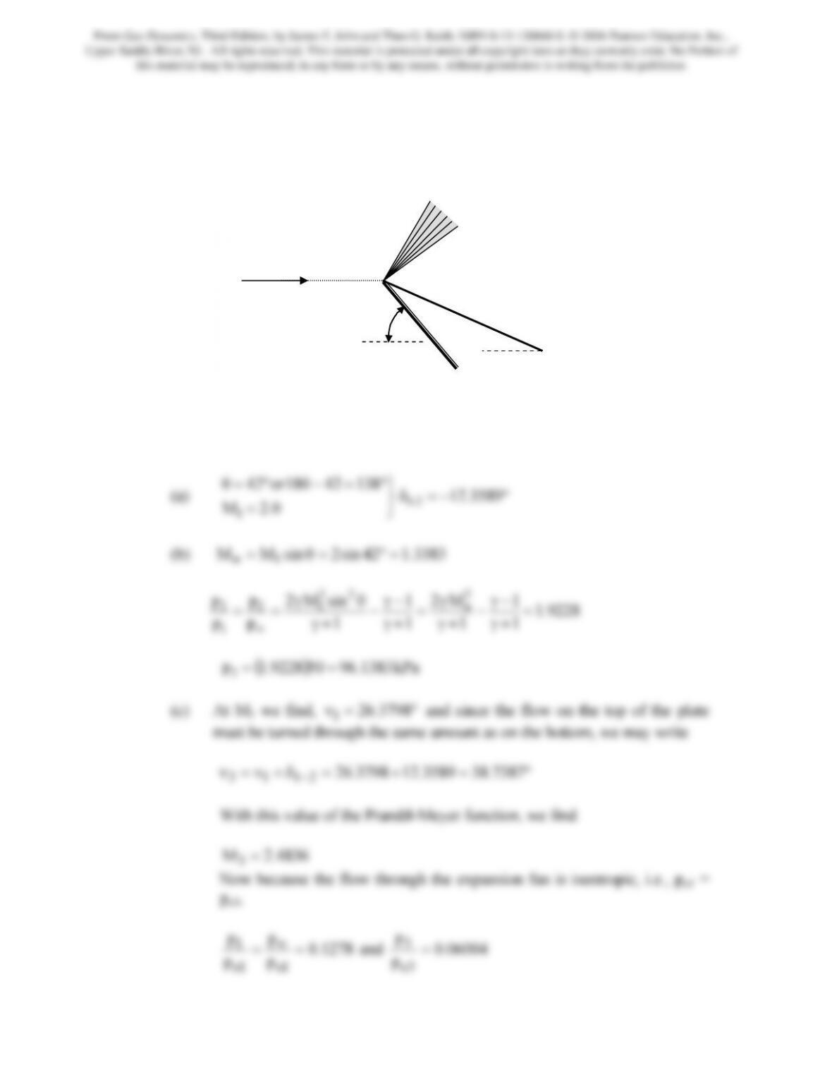
supersonic air stream of Mach 2.0 (Figure P7.6). Below the plate, an oblique shock wave
From Gas Dynamics, Third Edition, by James E. John and Theo G. Keith. ISBN 0-13-120668-0. © 2006 Pearson Education, Inc.,
Upper Saddle River, NJ. All rights reserved. This material is protected under all copyright laws as they currently exist. No Portion of
this material may be reproduced, in any form or by any means, without permission in writing from the publisher.
136
starts at the leading edge, making an angle of 42° with the stream direction. On the upper
side, an expansion occurs at the leading edge.
(a) Find the angle of attack, AoA, of the plate.
(b) What is the pressure on the lower surface of the plate?
(c) What is the pressure on the upper surface of the plate?
Figure P7.9
From the oblique shock relations,
1278.0
p
p
1o1o
p
3o
42º
p∞ = 50 kPa
M1 = 2
Α
οΑ
From Gas Dynamics, Third Edition, by James E. John and Theo G. Keith. ISBN 0-13-120668-0. © 2006 Pearson Education, Inc.,
Upper Saddle River, NJ. All rights reserved. This material is protected under all copyright laws as they currently exist. No Portion of
this material may be reproduced, in any form or by any means, without permission in writing from the publisher.
137
06004.0
p
p
p1o
33 ===
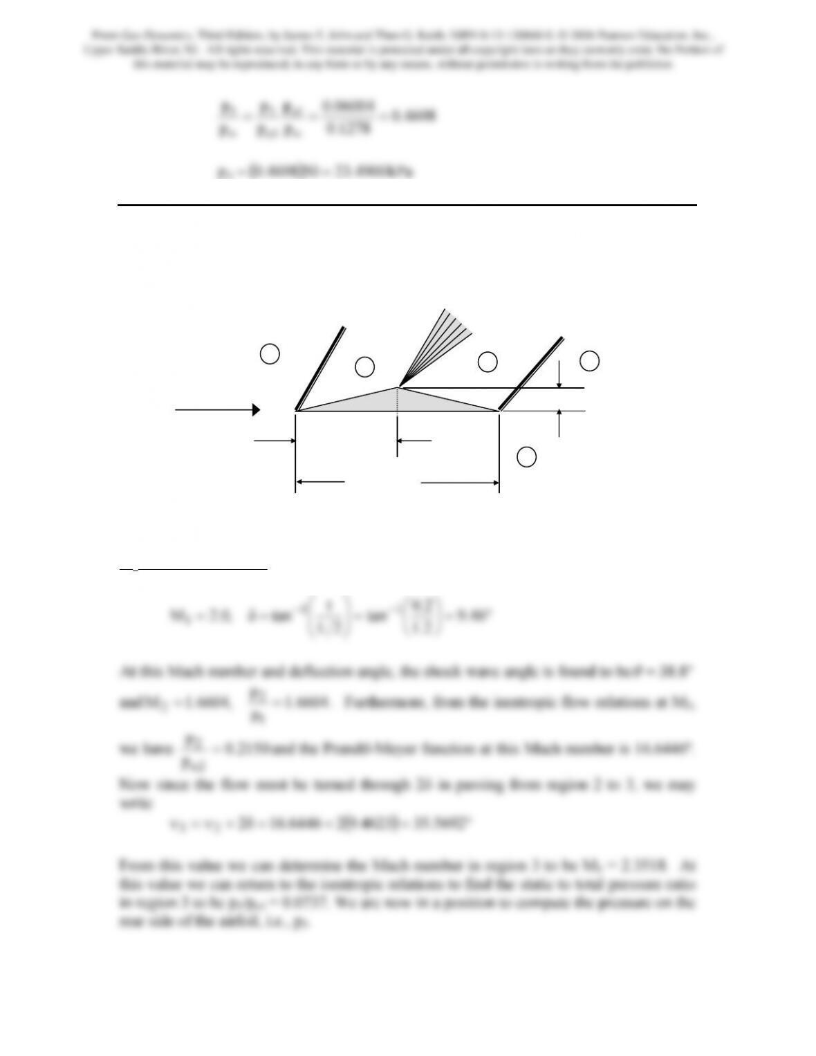
Problem 10. – A two-dimensional supersonic wing has the profile shown in Figure P7 .7.
At zero angle of attack, determine the drag force on the wing per unit length of span at
Mach 2 and at Mach 4. Repeat for the lift force. Take the maximum thickness of the
airfoil to be 0.2m.
Figure P7.7
M1 = 2.0 computations
⎞
⎛
⎞
⎛
2.0
t
t = 0.2
m
L/2 = 1.2m
L = 2.4m
M1
1 24
3
5
From Gas Dynamics, Third Edition, by James E. John and Theo G. Keith. ISBN 0-13-120668-0. © 2006 Pearson Education, Inc.,
Upper Saddle River, NJ. All rights reserved. This material is protected under all copyright laws as they currently exist. No Portion of
this material may be reproduced, in any form or by any means, without permission in writing from the publisher.
1
p
p
p
p
2o
3o
3
3=
⎞
⎛
⎞
⎛
⎞
⎛
⎞
⎛
()( )( )( )
m/kN510.52.13837.112080.334.220
2
321
−=+−=
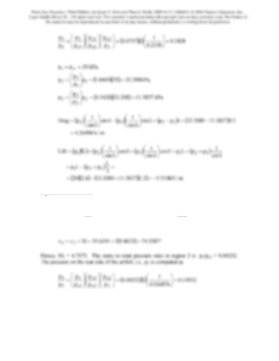
M1 = 4.0 computations
At this Mach number and the deflection angle of 9.4623º, °= 7505.21θ
and 3966.2
p
p
, 3241.3M
1
2
2== . Furthermore, at M2, 016876.0
p
p
2o
2=and ν2 =
55.6341º. Therefore,
From Gas Dynamics, Third Edition, by James E. John and Theo G. Keith. ISBN 0-13-120668-0. © 2006 Pearson Education, Inc.,
Upper Saddle River, NJ. All rights reserved. This material is protected under all copyright laws as they currently exist. No Portion of
this material may be reproduced, in any form or by any means, without permission in writing from the publisher.
139
p
kPa,20pp
2
1
⎞
⎛
== ∞
()( )( )( )
m/kN107.182.11572.7932.474.220
2
321
−=+−=
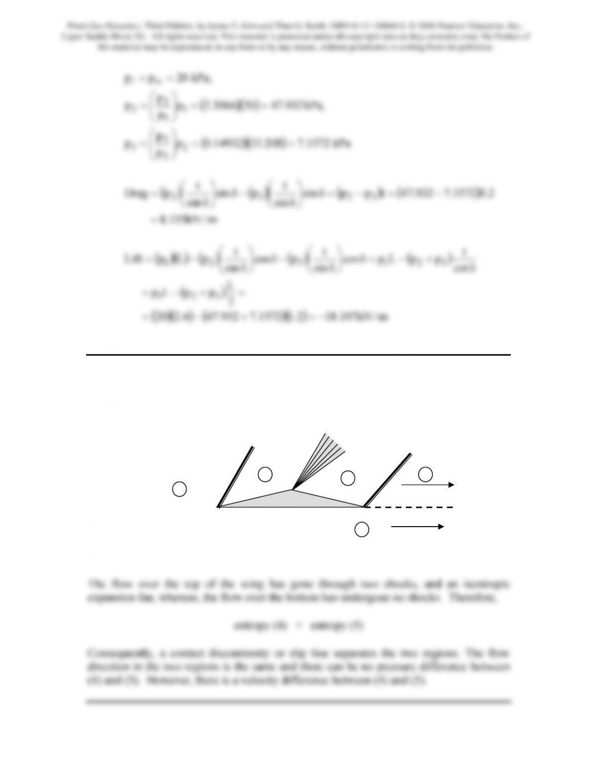
Problem 11. In Problem 10, a compression occurs at the trailing edge, with the resultant
flows in regions (a) and (b) parallel (Figure P7.11). Is there any difference in pressure,
velocity, or entropy between regions (a) and (b)? Discuss.
Figure P7.11
entropy (4) > entropy (5)
Consequently, a contact discontinuity or slip line separates the two regions. The flow
direction in the two regions is the same and there can be no pressure difference between
(4) and (5). However, there is a velocity difference between (4) and (5).
1
2 4
3
5
From Gas Dynamics, Third Edition, by James E. John and Theo G. Keith. ISBN 0-13-120668-0. © 2006 Pearson Education, Inc.,
Upper Saddle River, NJ. All rights reserved. This material is protected under all copyright laws as they currently exist. No Portion of
this material may be reproduced, in any form or by any means, without permission in writing from the publisher.
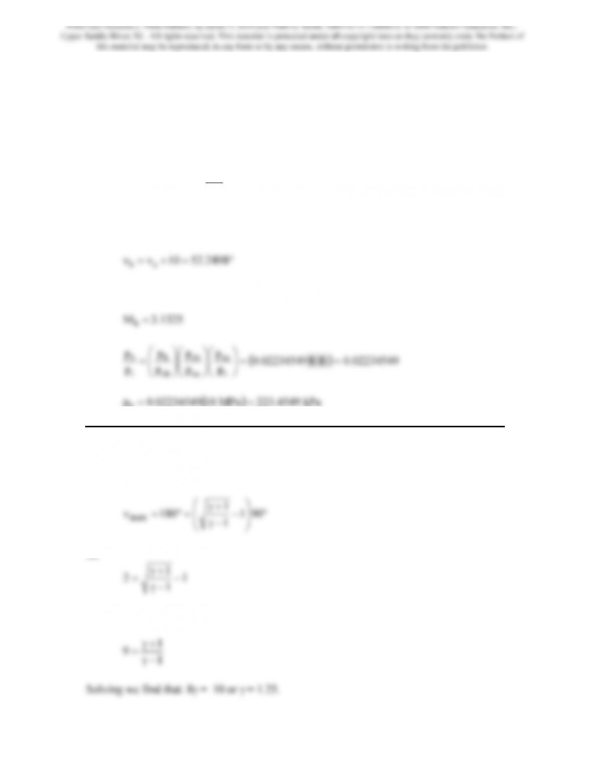
Problem 12. – A reservoir containing air at 10 MPa is discharged through a converging-
diverging nozzle of area ratio 3.0. An expansion fan is observed at the exit, with the flow
immediately downstream of the fan turned through an angle of 10°. Determine the
pressure of the region into which the nozzle is exhausting, if the air can be assumed to
behave as a perfect gas with constant γ = 1.4.
For the given area ratio: 0.3
*A
A=we can determine the corresponding Mach number
for the supersonic case to be Me = 2.6374. At this Mach number, the Prandtl-Meyer
function is found to be νe = 42.2498°. After the exiting flow is turned through 10º the
Prandtl-Meyer function is
From this value, we can find the corresponding Mach number
Problem 13. –Determine the value of γ for which νmax = 180°.
From Eq.(7.15)
So
1
1
−γ
+γ
or
From Gas Dynamics, Third Edition, by James E. John and Theo G. Keith. ISBN 0-13-120668-0. © 2006 Pearson Education, Inc.,
Upper Saddle River, NJ. All rights reserved. This material is protected under all copyright laws as they currently exist. No Portion of
this material may be reproduced, in any form or by any means, without permission in writing from the publisher.
141
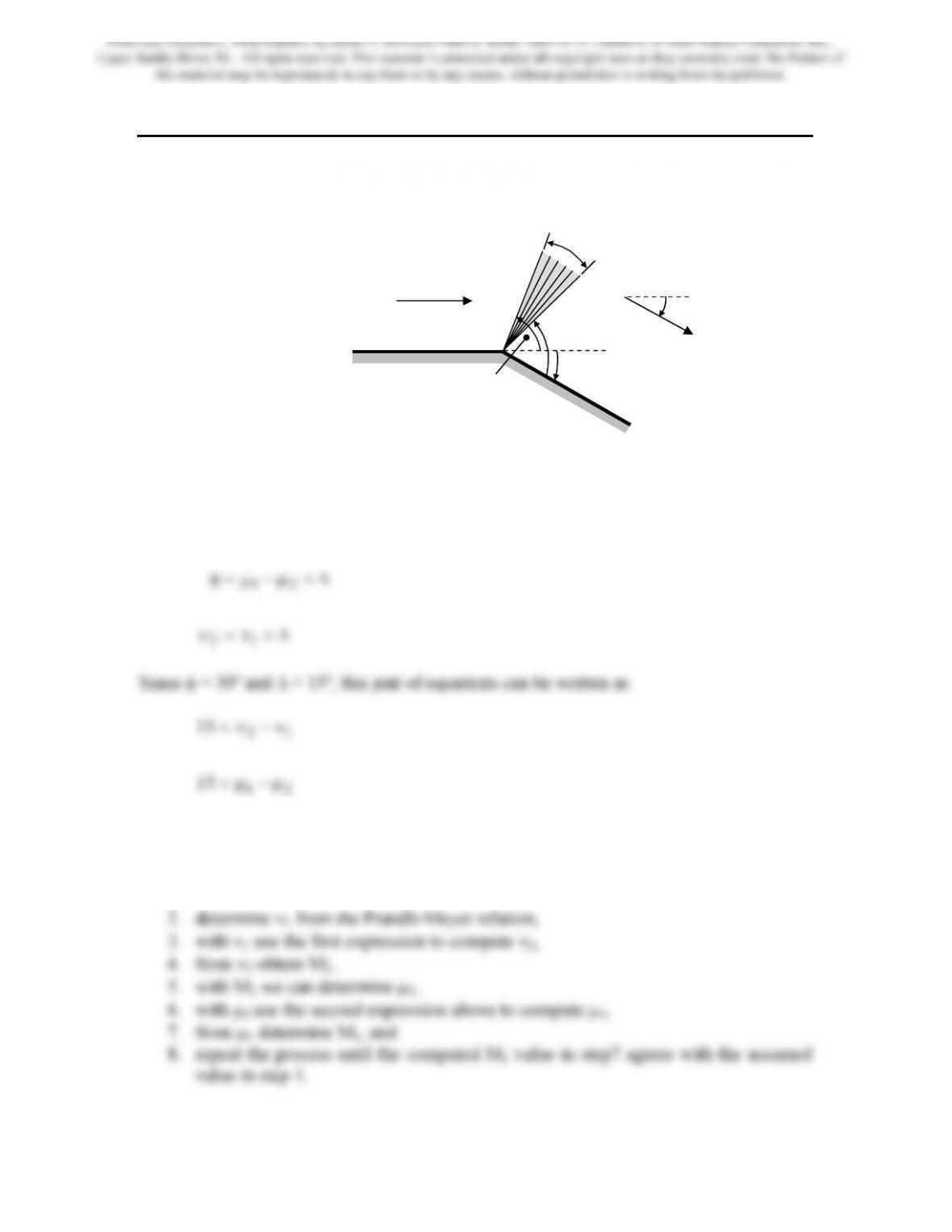
Problem 14. – For the geometry shown in P7.15 along with the given values of the fan
angle and the deflection angle, determine M1 and M2.
Figure P7.14
The solution of this problem requires a trial and error approach involving the following
two equations
∆+µ−µ=φ
21
21
15
µ−µ=
Now since both µ1 and ν1 depend only on M1 and since both µ2 and ν2 depend only on
M2, then the above pair represents two equations with two unknowns. One procedure to
solve the pair is
1. assume an M1,
(
α
2 –
α
1) =
−
15°
µ1
φ
= 30°
µ2
α
1 = 0° α2 = −15°
From Gas Dynamics, Third Edition, by James E. John and Theo G. Keith. ISBN 0-13-120668-0. © 2006 Pearson Education, Inc.,
Upper Saddle River, NJ. All rights reserved. This material is protected under all copyright laws as they currently exist. No Portion of
this material may be reproduced, in any form or by any means, without permission in writing from the publisher.
142
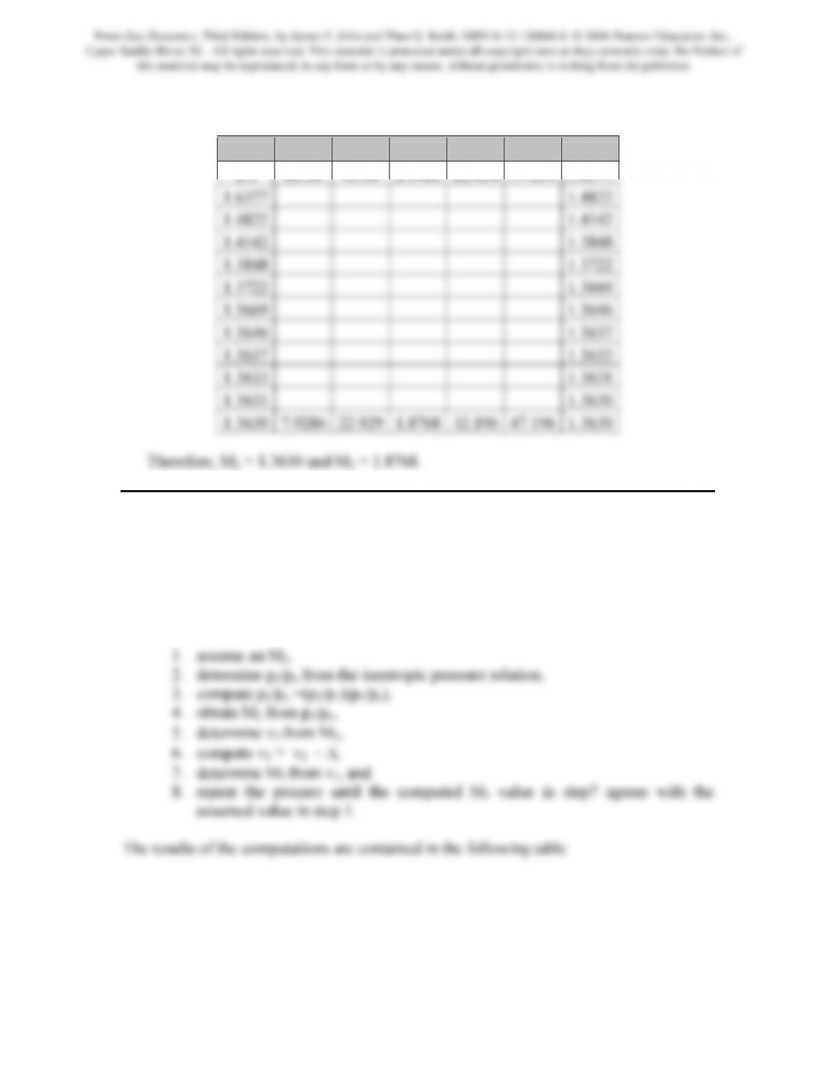
The following table contains some of the computations from this process
M1 ν1 ν2 M2 µ2 µ1 M1
Problem 15. – For the geometry of Figure P7.14, and for given values of the wall turning
angle, ∆, and the static pressure ratio across the expansion fan, p2/p1, define a process that
will yield M1 and M2. Use the process to solve for these Mach numbers if p2 = 0.4p1 and
∆ = 10°. Take γ = 1.4.
The following outlines a computational process
From Gas Dynamics, Third Edition, by James E. John and Theo G. Keith. ISBN 0-13-120668-0. © 2006 Pearson Education, Inc.,
Upper Saddle River, NJ. All rights reserved. This material is protected under all copyright laws as they currently exist. No Portion of
this material may be reproduced, in any form or by any means, without permission in writing from the publisher.
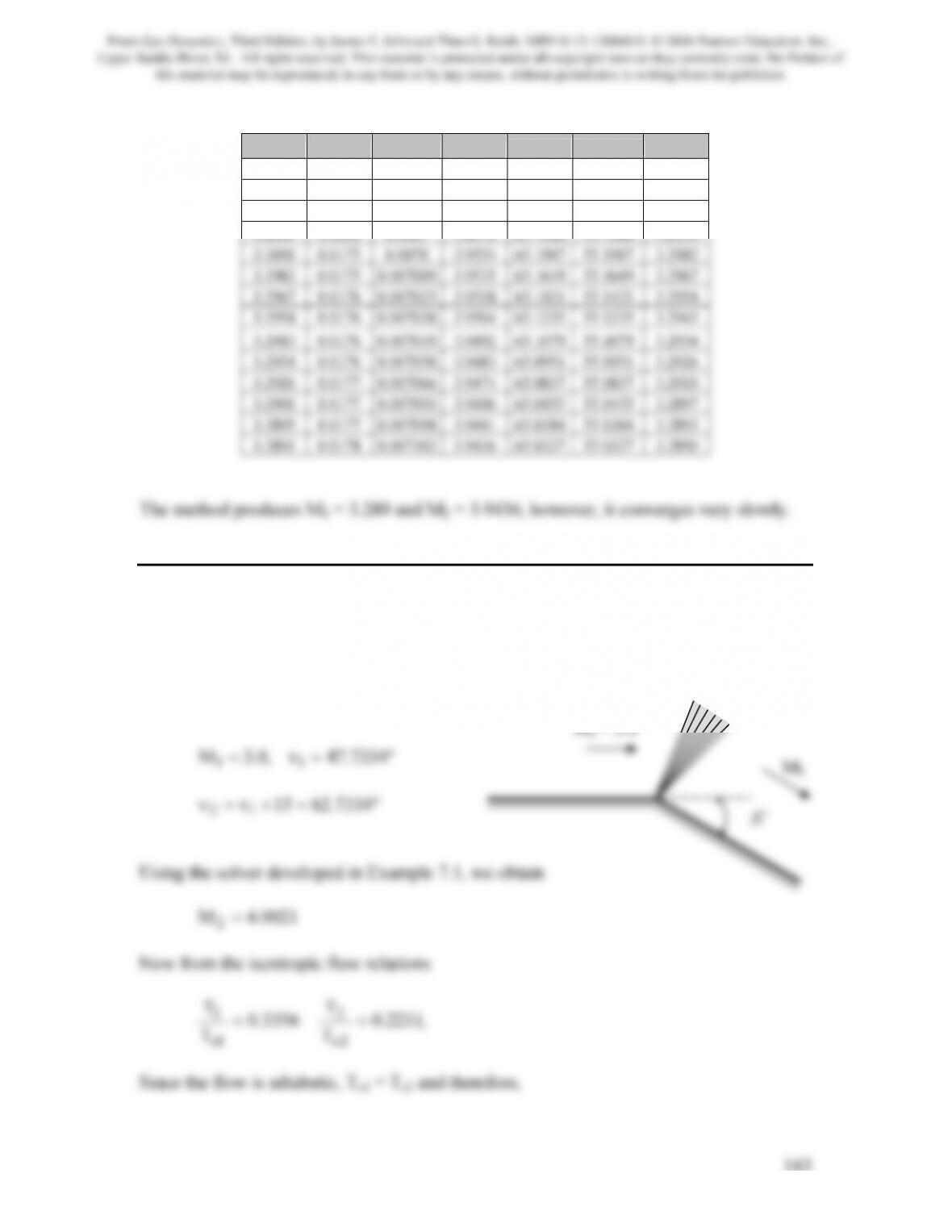
M1 p1/po p2/po M2 ν2 ν1 M1
2.0000 0.1278 0.051122 2.5872 41.1251 31.1251 2.1767
2.5000 0.0585 0.023411 3.1011 51.6699 41.6699 2.6114
3.0000 0.0272 0.010889 3.6318 60.5757 50.5757 3.0428
3.2000 0.0202 0.0081 3.8472 63.7088 53.7088 3.2134
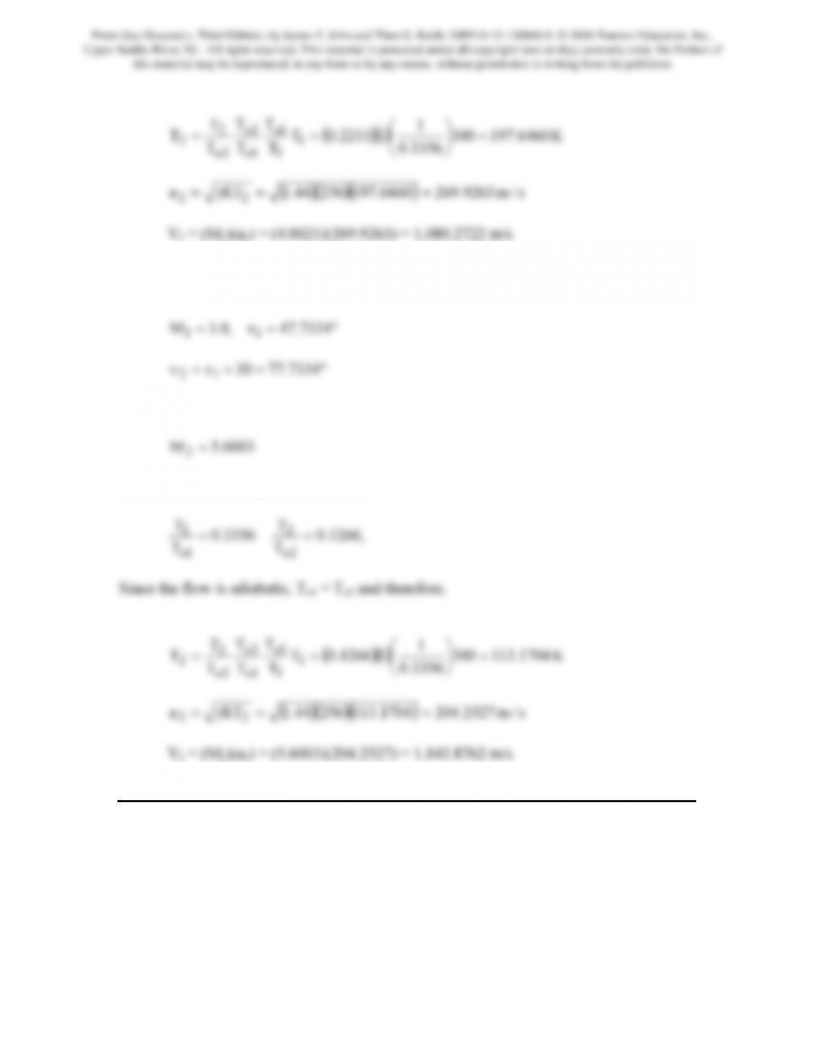
Problem 16. – A gas (γ = 1.44, R = 256 J/kg·K) flows towards a convex corner with
M1 = 3 and T1 = 300 K. Determine the downstream Mach number M2 and the
downstream velocity V2 if the wall is turned 15°. Repeat the calculations if the wall is
turned 30°.
Case (a) ∆ = 15º
M1 = 3.0
From Gas Dynamics, Third Edition, by James E. John and Theo G. Keith. ISBN 0-13-120668-0. © 2006 Pearson Education, Inc.,
Upper Saddle River, NJ. All rights reserved. This material is protected under all copyright laws as they currently exist. No Portion of
this material may be reproduced, in any form or by any means, without permission in writing from the publisher.
144
Case (b) ∆ = 30º
Using the solver developed in Example 7.1, we obtain
Now from the isentropic flow relations
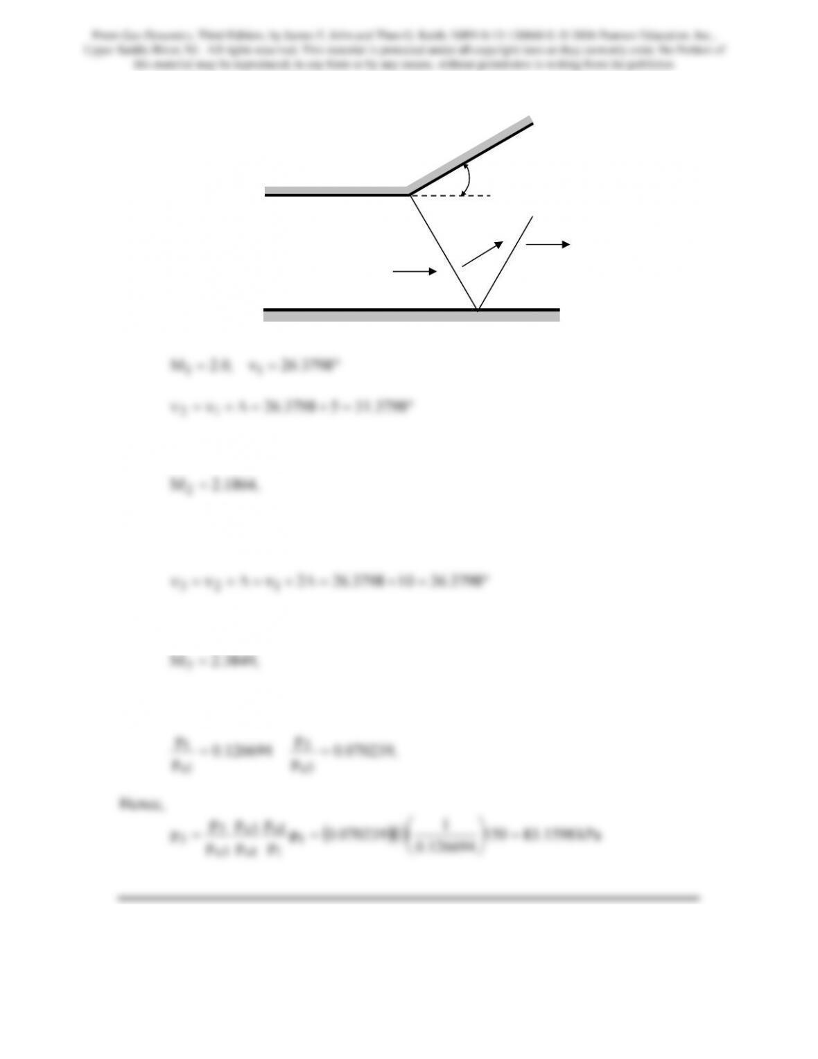
Problem 17. – Air (γ = 1.4) at M1 = 2 and p1 = 150 kPa flows in a duct as shown in
Figure 7.15. The upper wall turns the uniform supersonic stream through 5° “away”
from the flow resulting in the formation of a Prandtl-Meyer fan at the corner. Waves of
the fan reflect off the lower surface of the duct. Determine the Mach number and
pressure downstream of the leading reflected expansion wave.
From Gas Dynamics, Third Edition, by James E. John and Theo G. Keith. ISBN 0-13-120668-0. © 2006 Pearson Education, Inc.,
Upper Saddle River, NJ. All rights reserved. This material is protected under all copyright laws as they currently exist. No Portion of
this material may be reproduced, in any form or by any means, without permission in writing from the publisher.
145
The flow configuration is shown in the following
Using the solver developed in Example 7.1, we obtain
Since the flow just downstream of the reflected leading wave was turned twice through
the expansion, we may write
=
+
So
Now from the isentropic relations at M1 and M3
p
p
3
1==
Problem 18. – When Theodor Meyer presented his dissertation in 1908, the Mach
number had not been named; it appeared 20 years later (see Ref. 2). Accordingly, at that
∆
º
M2
M1 = 2.0
M3
From Gas Dynamics, Third Edition, by James E. John and Theo G. Keith. ISBN 0-13-120668-0. © 2006 Pearson Education, Inc.,
Upper Saddle River, NJ. All rights reserved. This material is protected under all copyright laws as they currently exist. No Portion of
this material may be reproduced, in any form or by any means, without permission in writing from the publisher.
146
time of Meyer’s thesis the static to total pressure ratio was used. Write the Prandtl-Meyer
function much like Meyer would have using the pressure ratio.
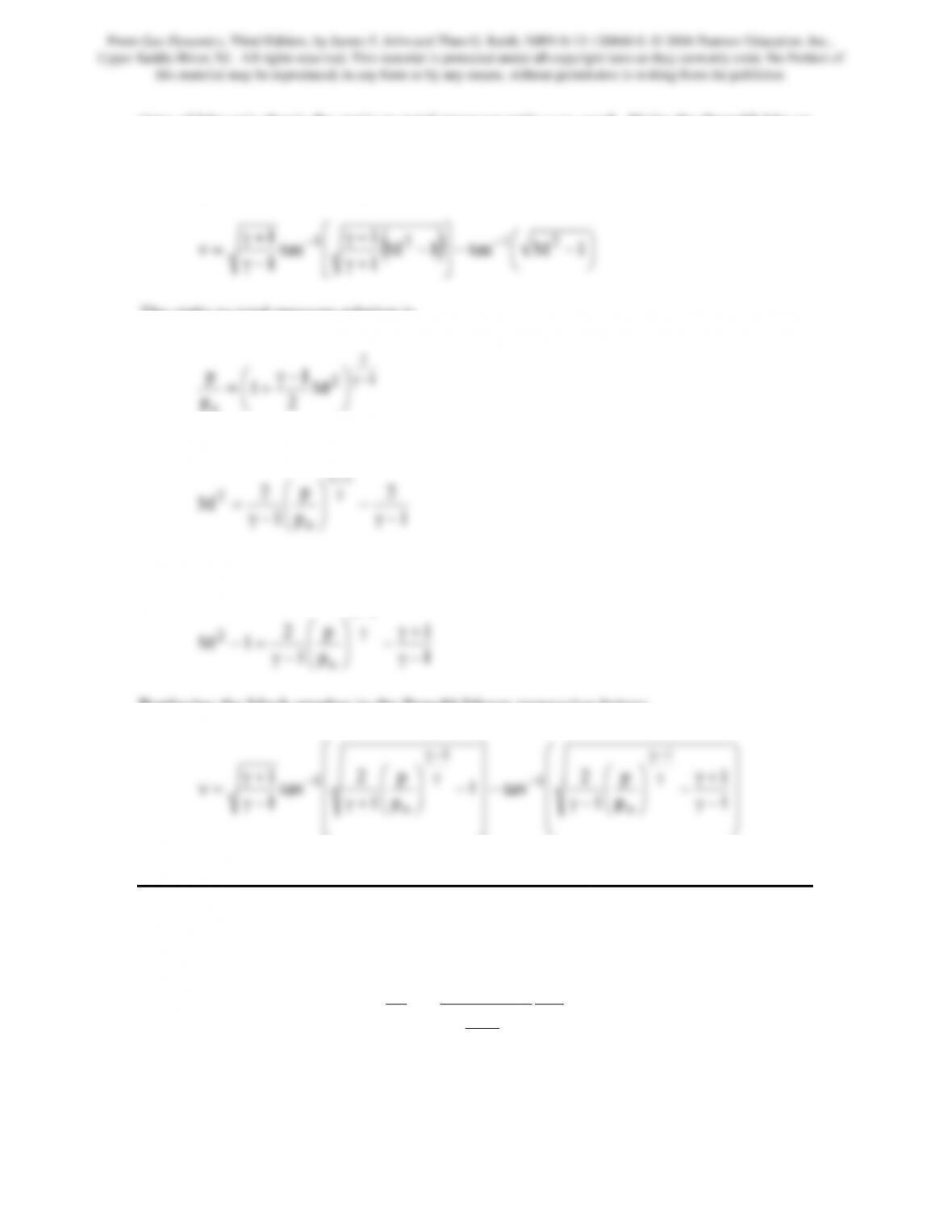
From Eq.(7.9) the Prandtl-Meyer function is written
The static to total pressure relation is
o
2
p
γ
⎠
⎝
Therefore,
1
2
p
p
1
2
1
o
2
−γ
⎟
⎠
⎞
⎜
⎝
⎛
−γ
−
γ
And so
1
p
2
1
2
+γ
⎞
⎛
−
γ
Replacing the Mach number in the Prandtl-Meyer expression brings
⎟
⎟
⎟
⎟
⎠
⎞
⎜
⎜
⎜
⎜
⎝
⎛
−γ
+γ
−
⎟
⎟
⎠
⎞
⎜
⎜
⎝
⎛
−γ
−
⎥
⎥
⎥
⎥
⎦
⎤
⎢
⎢
⎢
⎢
⎣
⎡
−
⎟
⎟
⎠
⎞
⎜
⎜
⎝
⎛
+γ−γ
+γ
=ν γ
−γ
−
γ
−γ
−
1
1
p
p
1
2
tan1
p
p
1
2
tan
1
1
1
o
1
1
o
1
Problem 19. – Obtain the following pressure-Mach number relation from the continuity
and normal momentum equations applied to a control volume containing a Mach wave:
M
dM
M
2
1
1
M
p
dp
2
2
−γ
+
γ
−=
Integrate this relation to derive the expression for the pressure ratio across the Mach
wave, p2/p1 in terms of M1 and M2, i.e., obtain Eq.(7.13).
From Gas Dynamics, Third Edition, by James E. John and Theo G. Keith. ISBN 0-13-120668-0. © 2006 Pearson Education, Inc.,
Upper Saddle River, NJ. All rights reserved. This material is protected under all copyright laws as they currently exist. No Portion of
this material may be reproduced, in any form or by any means, without permission in writing from the publisher.
147
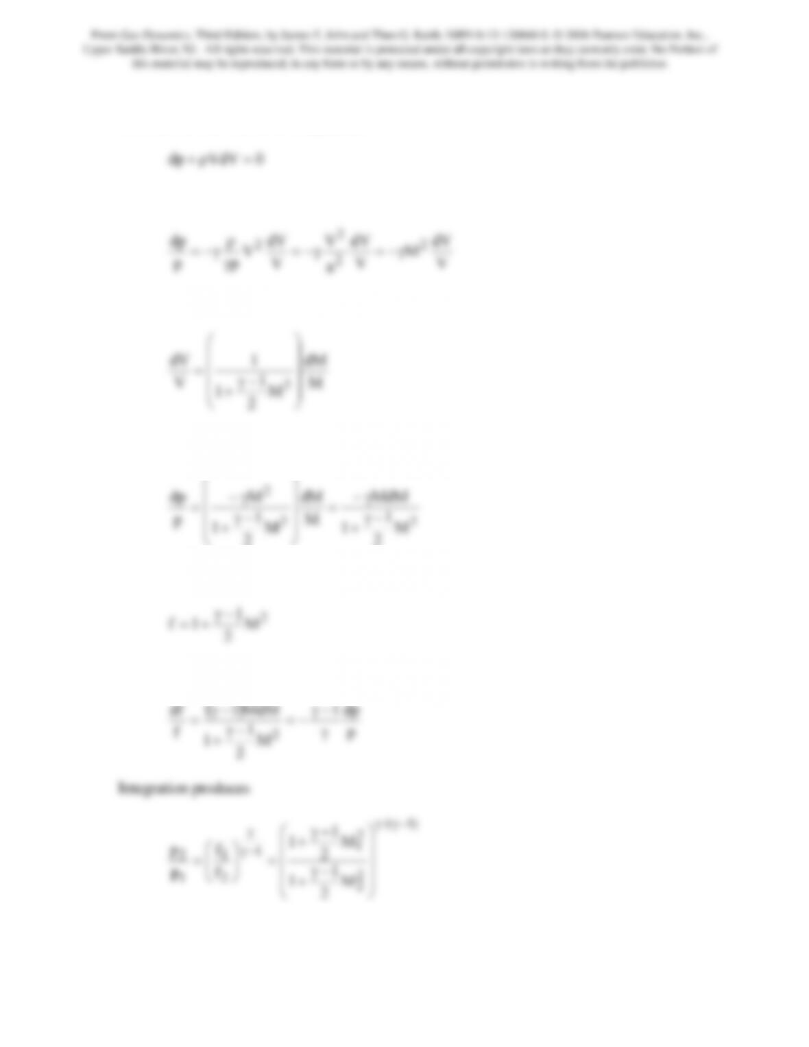
From the normal momentum equation,
Hence,
V
V
a
V
pp
2
γ
But from Eq.(7.6)
M
M
2
1
1
V
2⎟
⎟
⎠
⎜
⎜
⎝
−γ
+
So that
22
2
M
2
1
1
MdM
M
dM
M
2
1
1
M
p
dp
−γ
+
γ−
=
⎟
⎟
⎟
⎟
⎠
⎞
⎜
⎜
⎜
⎜
⎝
⎛
−γ
+
γ−
=
If
2
Take the logarithm and then differentiate to obtain
2
2
2
1
M
2
1
1
f
p
⎟
⎟
⎠
⎜
⎜
⎝
−γ
+
⎟
⎠
⎜
⎝
From Gas Dynamics, Third Edition, by James E. John and Theo G. Keith. ISBN 0-13-120668-0. © 2006 Pearson Education, Inc.,
Upper Saddle River, NJ. All rights reserved. This material is protected under all copyright laws as they currently exist. No Portion of
this material may be reproduced, in any form or by any means, without permission in writing from the publisher.
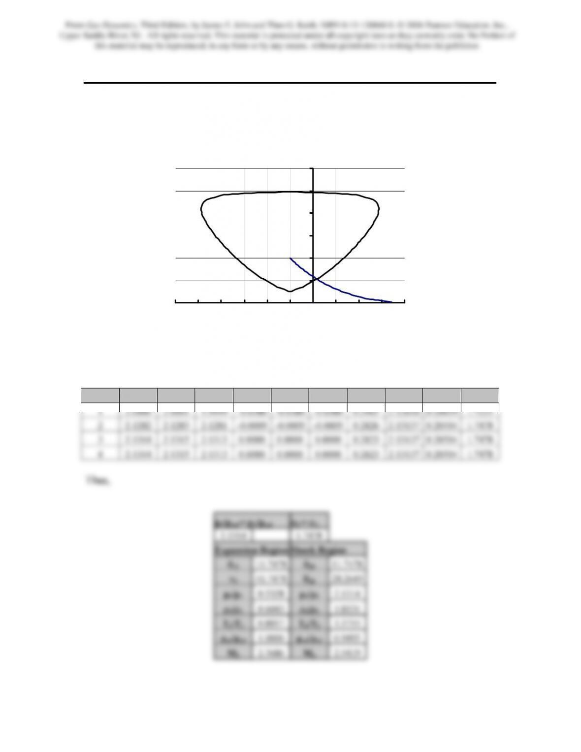
Problem 20. – Repeat Example 7.5 for γ = 1.25.
The pressure-flow direction diagram obtained for this flow is
0
2
4
6
8
10
12
-60 -50 -40 -30 -20 -10 0 10 20 30 40
The numerical solution for the intersection of the two curves is contained in the following
table
iteration yold y+∆ y-∆ f(y) f(y+∆) f(y-∆) ∆f/∆y ynew x x (deg)
From Gas Dynamics, Third Edition, by James E. John and Theo G. Keith. ISBN 0-13-120668-0. © 2006 Pearson Education, Inc.,
Upper Saddle River, NJ. All rights reserved. This material is protected under all copyright laws as they currently exist. No Portion of
this material may be reproduced, in any form or by any means, without permission in writing from the publisher.