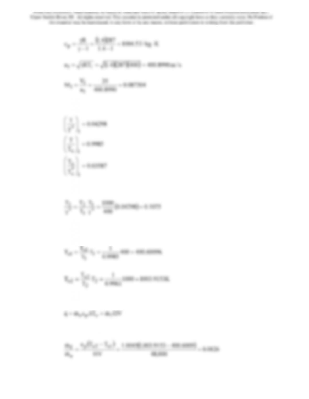
8990.400
a
1
At this Mach number we find from the Rayleigh relations that
03587.0
T
T
9985.0
T
T
04298.0
T
T
1
*
o
o
1
o
1
*
=
⎟
⎟
⎠
⎞
⎜
⎜
⎝
⎛
=
⎟
⎟
⎠
⎞
⎜
⎜
⎝
⎛
=
⎟
⎟
⎠
⎞
⎜
⎜
⎝
⎛
Now
()
1075.004298.0
400
T
T
T
*
1
*
From this temperature ratio, we may use the Rayleigh relations to find that M2 = 0.14038.
At this Mach number, we find that (T/To)2 = 0.9961. To1 and To2 are computed as follows
K9153.10031000
9961.0
1
T
T
T
T
K6009.400400
9985.0
1
T
T
T
T
2
2
2o
2o
1
1
1o
1o
===
===
From an energy balance we have
Therefore, the fuel air ratio is
From Gas Dynamics, Third Edition, by James E. John and Theo G. Keith. ISBN 0-13-120668-0. © 2006 Pearson Education, Inc.,
Upper Saddle River, NJ. All rights reserved. This material is protected under all copyright laws as they currently exist. No Portion of
this material may be reproduced, in any form or by any means, without permission in writing from the publisher.
223
To choke the flow To2 = To*, where
So
(
)
()
2253.0
000,48
6009.4001322.168,110045.1
HV
TTc
m
m1o
*
op
a
f=
−
=
−
=
&
&
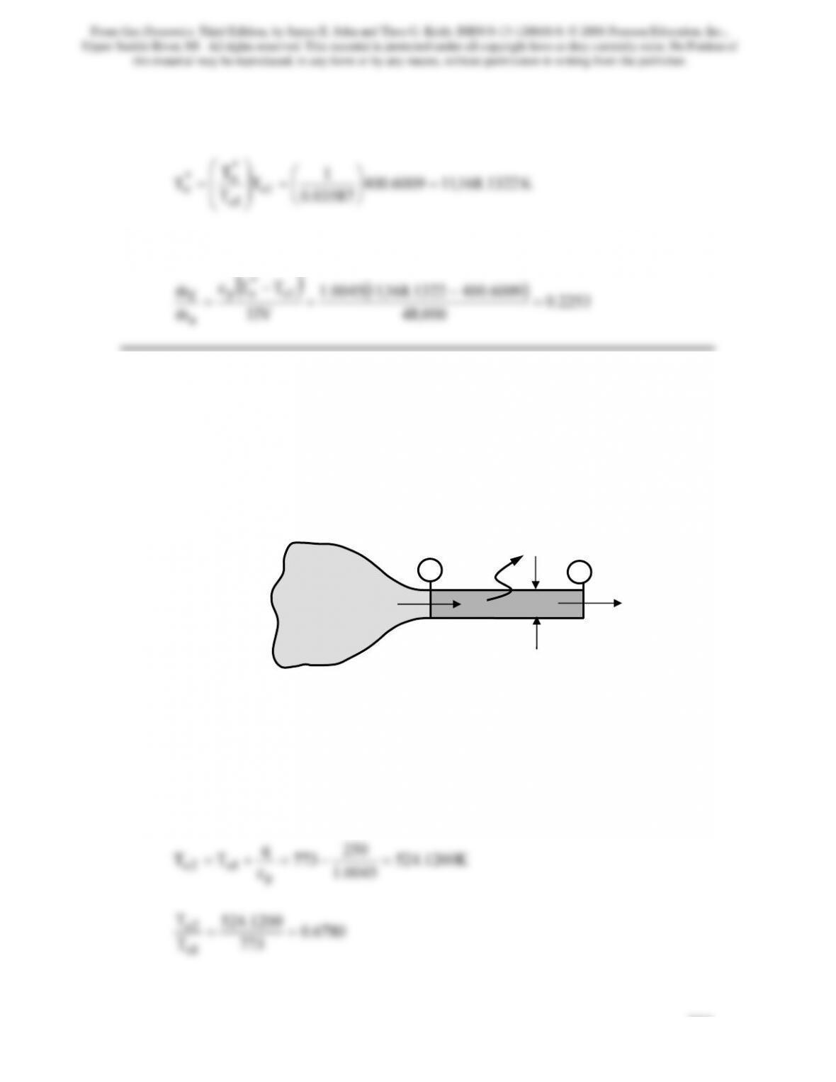
Problem 10. – Air (γ = 1.4, R = 0.287 kJ/kg · K and cp = 1.0045 kJ/kg · K) flows through
a constant-area duct is connected to a reservoir at a temperature of 500ºC and a pressure
of 500 kPa by a converging nozzle, as shown in Figure P10.10. Heat is lost at the rate of
250 kJ /kg. (a) Determine the exit exit pressure and Mach number and the mass flow rate
for a back pressure of 0 kPa. (b) Determine the exit pressure and Mach number when a
normal shock stands in the exit plane of the duct.
Figure Pl0.10
(a) Because the back pressure is 0 kPa and because heat is removed from the air, the
flow in the duct will be supersonic and accelerating. This will occur only if M1 = 1.0.
Therefore, To1 = To* = 773K. From isentropic flow relations, (T/To)1 = 0.8333 and
(p/po)1 = 0.5283. So, T1 = (0.8333)773= 644.1667K and p1 = p* = (0.5283)500 =
264.1500 kPa. From the energy balance on the duct
250
q
1 2
q = 250 kJ/kg
pr = 500 kPa
Tr = 500ºC
pb = 0 kPa
D = 0.02m
From Gas Dynamics, Third Edition, by James E. John and Theo G. Keith. ISBN 0-13-120668-0. © 2006 Pearson Education, Inc.,
Upper Saddle River, NJ. All rights reserved. This material is protected under all copyright laws as they currently exist. No Portion of
this material may be reproduced, in any form or by any means, without permission in writing from the publisher.
224
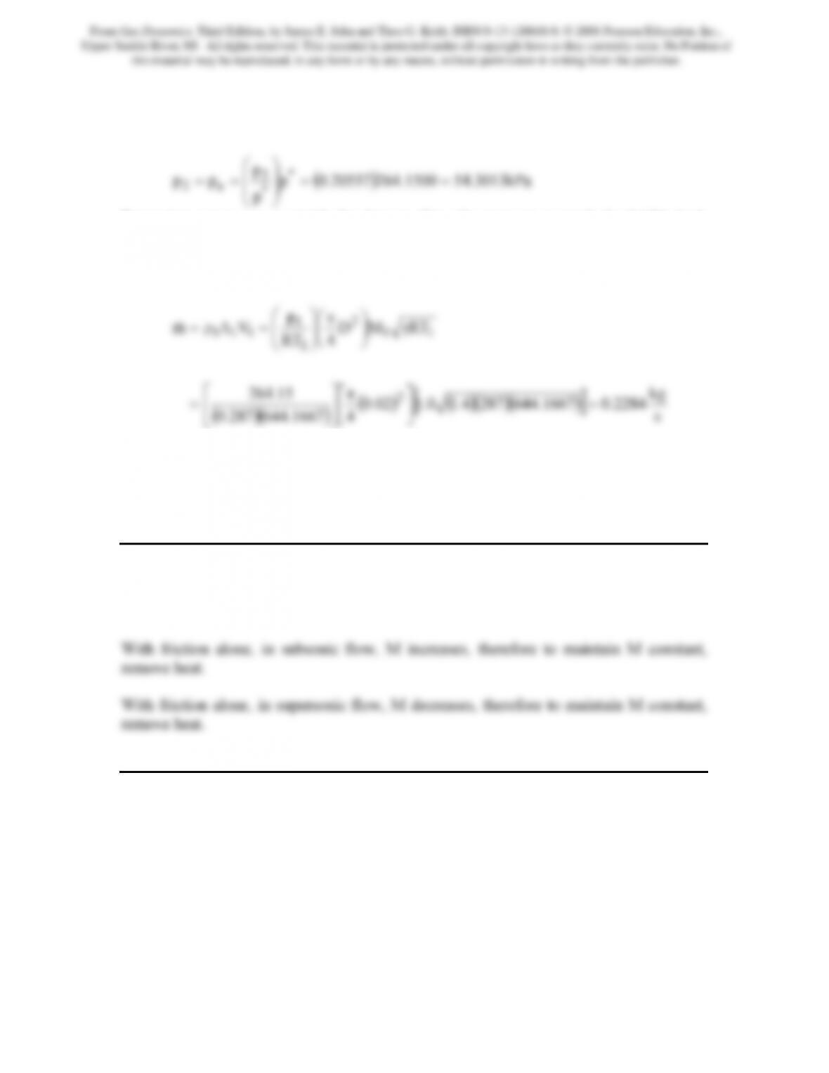
From the Rayleigh relations we find, M2 = 2.7613 and at this Mach number
p2/p* = 0.20557. Accordingly,
p
*
e2 ==
⎟
⎠
⎜
⎝
Expansion waves occur outside the duct to allow the pressure to reach the 0 kPA back
pressure.
The mass flow rate is computed as follows
()( )
() ()()( )
[]
s
kg
2284.01667.6442874.10.102.0
41667.644287.0
15.264
2
=
⎥
⎦
⎤
⎢
⎣
⎡π
⎥
⎦
⎤
⎢
⎣
⎡
=
(b) The Mach number just upstream of the shock is 2.7613. From the normal shock
relations we find the Mach number on the downstream side to be 0.4910 and the exit
pressure is determined by multiplying the static pressure ratio across the shock 8.7289
times the pressure found in part (a), i.e., pe = (54.3013)8.7289 = 473.9906kPa = pb.
Problem 11. – Consider flow in a constant-area duct with friction and heat transfer. To
maintain a constant subsonic Mach number, should heat be added or removed? Repeat
for supersonic flow.
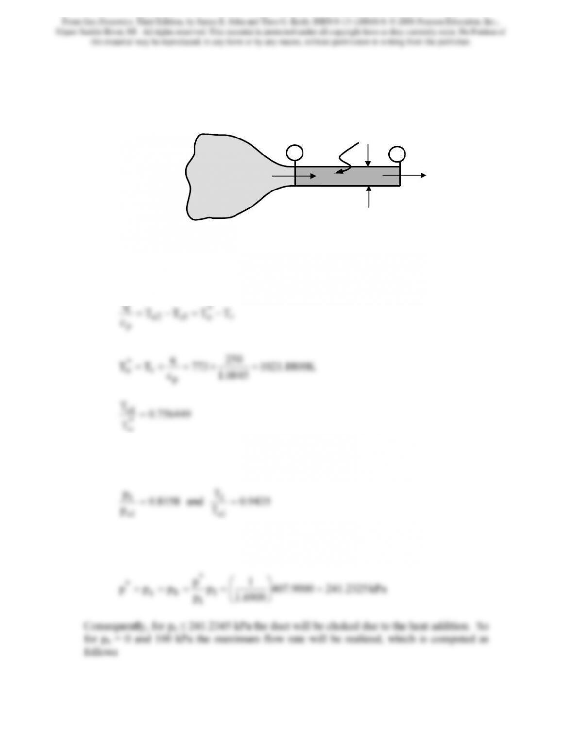
Problem 12. – For the system shown in Problem 10, determine the mass flow rate if 250
kJ/kg of heat energy is added to the flow in the duct. The duct diameter is 2 cm. Repeat
for a back pressure of 100 kPa. Working fluid is air (γ = 1.4, cp = 1004.5J/ kg · K and
R = 0.287 kJ/kg · K).
From Gas Dynamics, Third Edition, by James E. John and Theo G. Keith. ISBN 0-13-120668-0. © 2006 Pearson Education, Inc.,
Upper Saddle River, NJ. All rights reserved. This material is protected under all copyright laws as they currently exist. No Portion of
this material may be reproduced, in any form or by any means, without permission in writing from the publisher.
225
Assume M2 = 1 so that the duct is choked. Accordingly, To2 = To*. Therefore from an
energy balance
*
TTTT
q−=−=
756449.0
T
*
o
At this value, the Rayleigh relations reveal that M1 = 0.5473 and therefore
p1/p* = 1.6909. The isentropic relations at this Mach number provide
8158.0
p
1o
T
1o
Since po1 = pr = 500 kPa and To1 = Tr = 773K, we can use these ratios to compute
p1 = (0.8158)500 = 407.9000 kPa and T1 = (0.9435)773 = 729.3255K. Furthermore,
1 2
q = 250 kJ/kg
pr = 500 kPa
Tr = 500ºC
pb = 0 kPa
D = 0.02m
From Gas Dynamics, Third Edition, by James E. John and Theo G. Keith. ISBN 0-13-120668-0. © 2006 Pearson Education, Inc.,
Upper Saddle River, NJ. All rights reserved. This material is protected under all copyright laws as they currently exist. No Portion of
this material may be reproduced, in any form or by any means, without permission in writing from the publisher.
226
()( )
s
kg
1814.0
43255.729287.0
p
2
1
=
⎞
⎛π
⎞
⎛
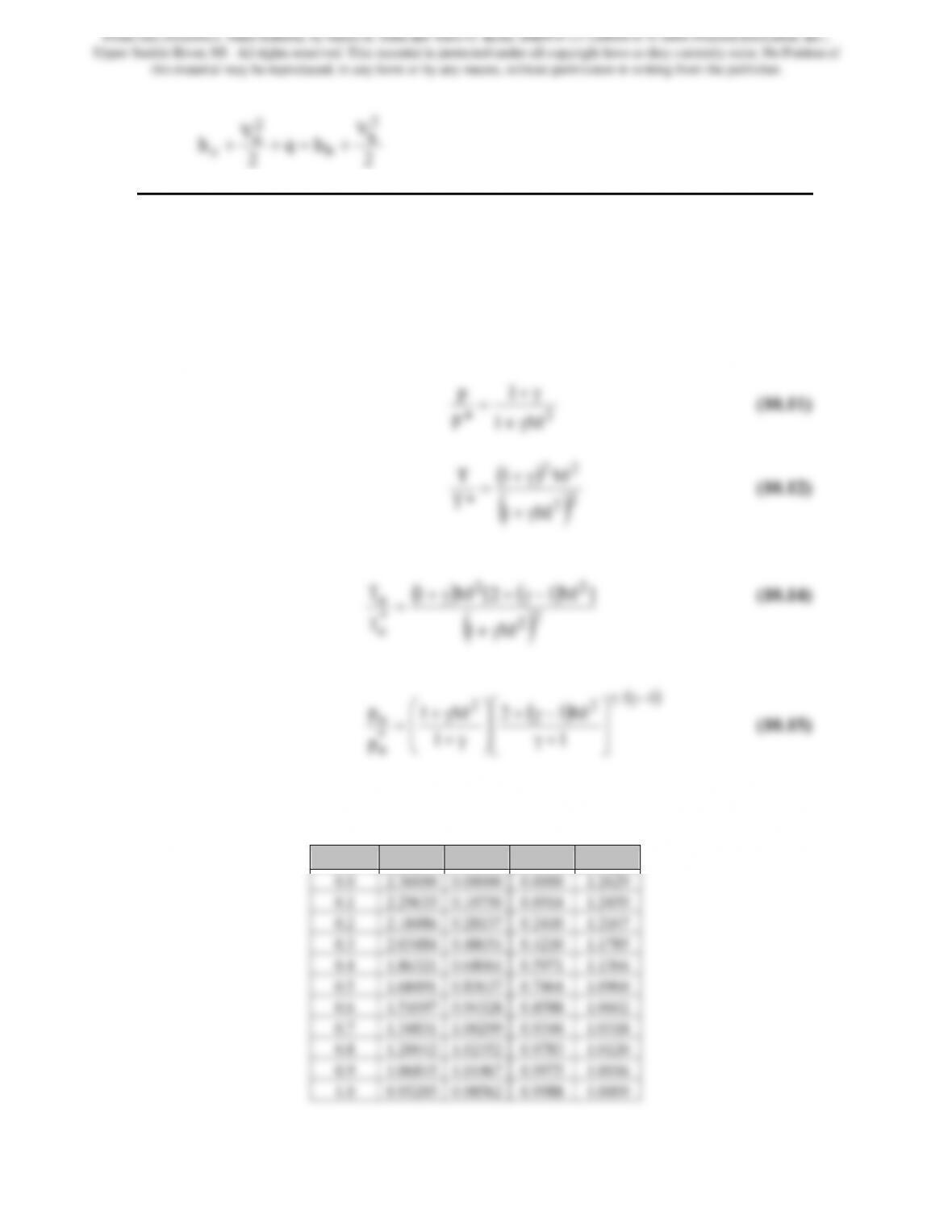
Problem 13. – A detonation wave (Figure P10.13) represents a shock sustained by
chemical reaction. Give the continuity, momentum, and energy equations for such a
wave, assuming that a chemical reaction taking place in the wave liberates heat q. Denote
properties of the unburned gas ahead of the wave by the subscript u and those of the
burned gases behind the wave by b. Write the equations for an observer traveling with the
wave.
Figure Pl0.l3
Detonation wave
(fixed with respect to observer)
ρ
u
Vu
pu
Tu
ρb
Vb
pb
Tb
From Gas Dynamics, Third Edition, by James E. John and Theo G. Keith. ISBN 0-13-120668-0. © 2006 Pearson Education, Inc.,
Upper Saddle River, NJ. All rights reserved. This material is protected under all copyright laws as they currently exist. No Portion of
this material may be reproduced, in any form or by any means, without permission in writing from the publisher.
2
V
hq
2
V
h
2
b
b
2
u
u+=++
Problem 14. – Develop a computer program that will yield values of p/p*, T/T*, *
oo T/T,
and *
oo p/p for Rayleigh line flow with the working fluid consisting of a perfect gas with
constant γ = 1.36. Use Mach number increments of 0.10 over the range M = 0 to M = 2.5.
The governing relations are
*
o
1
1
p
⎥
⎦
⎢
⎣
+γ
⎟
⎠
⎜
⎝
γ+
The following is the spreadsheet computed values
M p/p* T/T* To/To* po*/po*
From Gas Dynamics, Third Edition, by James E. John and Theo G. Keith. ISBN 0-13-120668-0. © 2006 Pearson Education, Inc.,
Upper Saddle River, NJ. All rights reserved. This material is protected under all copyright laws as they currently exist. No Portion of
this material may be reproduced, in any form or by any means, without permission in writing from the publisher.
228
1.1 0.85012 0.94381 0.9879 1.0100
Problem 15. – Oxygen (γ = 1.4 and R = 0.2598 kJ/kg · K) is to be pumped through an
uninsulated 2.5-cm pipe, 1000 m long (Figure P10.15). A compressor is available at the
oxygen source capable of providing a pressure of 1 MPa. If the supply pressure is to be
101 kPa, determine the mass flow rate through the system and the compressor power
required. Assume isothermal flow at T = 15˚C.
Figure P10.15
Now from Eq.(9.46)
2
1
2
2
2
1
M
ln
M1
M1
fL +
γ−
−
γ−
=
1
2
2
1
M
p
compressor
p = 101 kPa p = 101 kPa
p = 1.0 MPa
1 2
From Gas Dynamics, Third Edition, by James E. John and Theo G. Keith. ISBN 0-13-120668-0. © 2006 Pearson Education, Inc.,
Upper Saddle River, NJ. All rights reserved. This material is protected under all copyright laws as they currently exist. No Portion of
this material may be reproduced, in any form or by any means, without permission in writing from the publisher.
229
Calling the ratio p1/p2 p and replacing M2 in the fL/D equation yields after a small
amount of algebra
2
1
2
2
1
2
2
1
2
2
1
Mp
Mp
Mp
M
D
⎟
⎠
⎜
⎝
γ
⎟
⎠
⎜
⎝
⎟
⎠
⎜
⎝
γ
⎟
⎠
⎜
⎝
γ
Solving for M1
()
⎟
⎠
⎞
⎜
⎝
⎛+γ
22
1
pln
D
fL
p
Since fL/D = (0.018)(1000)/(0.025) = 720, (p1/p2)2 = (1000/101)2 = 98.0296 and γ = 1.4,
substitution produces M1 = 0.0312. The mass flow rate is computed as follows:
() ()( )( )
s/kg0662.0
42882598.0
RTAM
RT
p
AVρm
11
1
1
11
=
⎠
⎝
⎥
⎦
⎢
⎣
γ
⎟
⎟
⎠
⎞
⎜
⎜
⎝
⎛
==
&
For isothermal compression:
1000
101
p
p
1
2
⎠
⎞
⎝
⎛
⎠
⎞
⎝
⎛
The power required is found by multiplying the work by the mass flow rate:
Problem 16. – Natural gas (assume the properties of methane: γ = 1.32 and
R = 0.5182 kJ/kg · K) is to be pumped over a long distance through a 7.5-cm-diameter
pipe (Figure P10.16). Assume the gas flow to be isothermal, with T = 15°C. Compressor
stations capable of delivering 20 kW to the flow are available, with each compressor
capable of raising the gas pressure isothermally to 500 kPa (inlet compressor pressure is
to be 120 kPa). How far apart should the compressor stations be located? Assume
isothermal compression in each compressor, with f = 0.017.
From Gas Dynamics, Third Edition, by James E. John and Theo G. Keith. ISBN 0-13-120668-0. © 2006 Pearson Education, Inc.,
Upper Saddle River, NJ. All rights reserved. This material is protected under all copyright laws as they currently exist. No Portion of
this material may be reproduced, in any form or by any means, without permission in writing from the publisher.
230
Figure P10.16
For isothermal compression:
The power required is equal to the work times the mass flow rate. Therefore, we can
determine the mass flow rate as follows:
()
025.0
4
500
Ap
Aρ
2
1
1
1=
⎥
⎥
⎦
⎢
⎢
⎣
⎟
⎠
⎞
⎜
⎝
⎛π
Therefore,
01429.0
3441.6
V
V
M1
1
1==
==
Now from Eq.(9.48)
1 2
compressor compressor
From Gas Dynamics, Third Edition, by James E. John and Theo G. Keith. ISBN 0-13-120668-0. © 2006 Pearson Education, Inc.,
Upper Saddle River, NJ. All rights reserved. This material is protected under all copyright laws as they currently exist. No Portion of
this material may be reproduced, in any form or by any means, without permission in writing from the publisher.
fL
fL
fL
max
max =−=
⎞
⎛
⎞
⎛
017.0
f
⎠
⎝
⎠
⎝
Problem 17. – Develop a computer program that will yield values of p/p*, fLmax/D,
*
oo T/T , and *
oo p/p for isothermal flow with the working fluid consisting of a perfect
gas with constant γ = 1.34. Use Mach number increments of 0.10 over the range M = 0.1
to M = 2.5.
The equations that govern this flow are
()
o
13
M
p
∗⎭
⎩
−γ
γ
Spreadsheet computation produces,
M p/p* T/T* po*/po* fLmax/D
0.100 10.8075 1.1680 5.8600 69.9953
From Gas Dynamics, Third Edition, by James E. John and Theo G. Keith. ISBN 0-13-120668-0. © 2006 Pearson Education, Inc.,
Upper Saddle River, NJ. All rights reserved. This material is protected under all copyright laws as they currently exist. No Portion of
this material may be reproduced, in any form or by any means, without permission in writing from the publisher.
0.800 1.2840 1.0552 1.0390 0.0770
0.900 1.1268 1.0284 1.0091 0.0155
Problem 18. – A subsonic stream of air (γ = 1.4, R = 0.287 kJ/kg · K and
cp = 1.0045 kJ/kg · K) flows through a linear, conically shaped, nozzle, i.e.,
D = Di + (De – Di)x/L. The diameter at the inlet is 2 cm and the diameter at the exit is 5
cm. The nozzle is 10 cm long. The entering Mach number is 0.6. Heat is added to flow
at a rate so that the stagnation temperature varies linearly with distance. The stagnation
temperature at the inlet is 300K and increases 30K per meter of nozzle. Use Heun’s
predictor-corrector scheme on a coarse grid that includes 11 grid points to determine the
Mach number distribution within the duct. To verify the computations determine the exit
Mach number for the case when the heat transfer is zero and compare it to the value
determined from isentropic flow computations.
Here we will determine the exit Mach number against which we can contrast the
computed value. To obtain this value we follow the usual procedure in which we use the
inlet Mach number to find (A/A*)i and then determine (A/A*)e from the following
From Gas Dynamics, Third Edition, by James E. John and Theo G. Keith. ISBN 0-13-120668-0. © 2006 Pearson Education, Inc.,
Upper Saddle River, NJ. All rights reserved. This material is protected under all copyright laws as they currently exist. No Portion of
this material may be reproduced, in any form or by any means, without permission in writing from the publisher.
Here the grid is divided into 10 pieces, i.e., ∆x = 0.01m and the results from applying
Heun’s method are contained in the following table
pt x Mi F(xi,Mi) Mp F(xi+1,Mp) Mi+1
Now introducing heat transfer into the computations on a coarse grid of 11 grid points
yields
pt x Mi F(xi,Mi) Mp F(xi+1,Mp) Mi+1
From Gas Dynamics, Third Edition, by James E. John and Theo G. Keith. ISBN 0-13-120668-0. © 2006 Pearson Education, Inc.,
Upper Saddle River, NJ. All rights reserved. This material is protected under all copyright laws as they currently exist. No Portion of
this material may be reproduced, in any form or by any means, without permission in writing from the publisher.
Problem 19. – A supersonic stream of air (γ = 1.4, R = 0.287 kJ/kg · K and cp = 1.004
kJ/kg · K) flows through a linear, conically shaped, nozzle, i.e., D = Di + (De – Di)x/L.
The diameter at the inlet is 2 cm and the diameter at the exit is 5 cm. The nozzle is 10 cm
long. The entering Mach number is 3. Heat is added to flow at a rate so that the
stagnation temperature varies linearly with distance. The stagnation temperature at the
inlet is 300K and increases 30K per meter of nozzle. The pressure is such that a normal
shock wave stands half way down the nozzle. Use Euler’s explicit method to determine
the Mach number distribution within the duct.
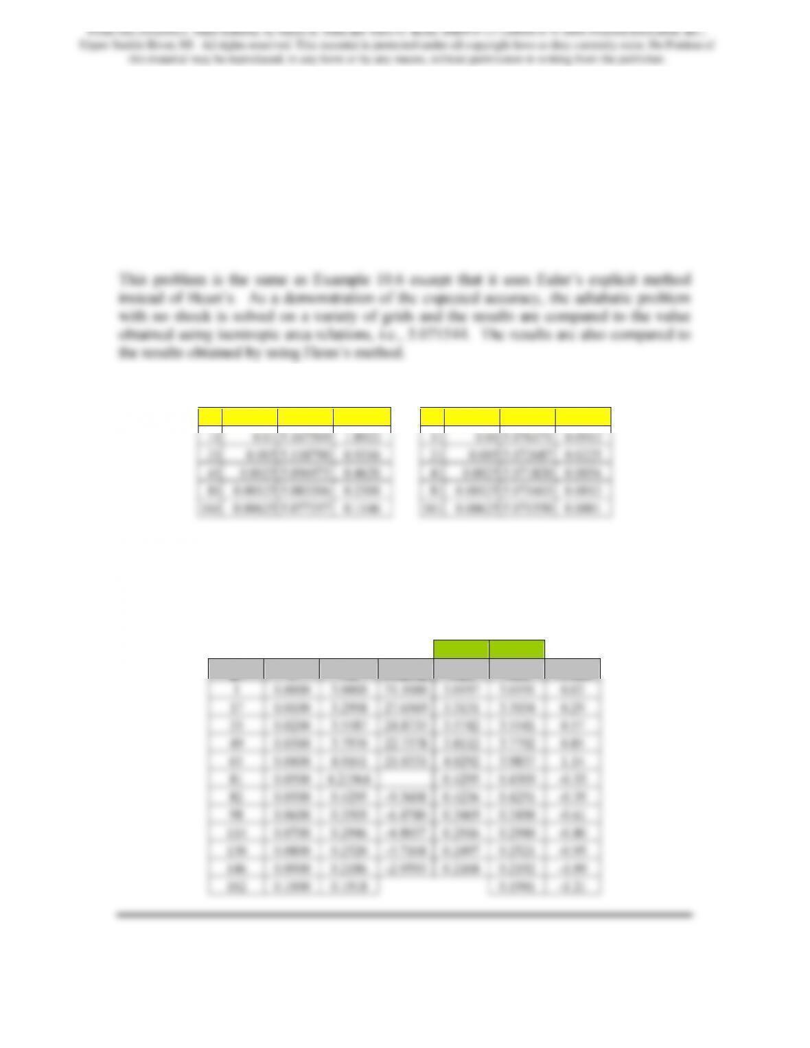
Euler’s Adiabatic Results Heun’s Adiabatic Results
Pts ∆x M (x=10) % error Pts ∆x M (x=10) % error
As can be seen, Heun’s method, which is a 2nd order method produces more accuracy for
the same grid size. Euler’s results are not great particularly at larger grid sizes.
Nonetheless, the following are summary results for the problem using Euler on the
smallest grid in the table above.
Euler Heun
pt x Mi F(xi,Mi) Mi+1 Mi+1 % diff
From Gas Dynamics, Third Edition, by James E. John and Theo G. Keith. ISBN 0-13-120668-0. © 2006 Pearson Education, Inc.,
Upper Saddle River, NJ. All rights reserved. This material is protected under all copyright laws as they currently exist. No Portion of
this material may be reproduced, in any form or by any means, without permission in writing from the publisher.

Problem 20. – A supersonic stream of air (γ = 1.3, R = 0.287 kJ/kg · K and cp = 1.004
kJ/kg · K) flows through a linear, conically shaped, nozzle, i.e., D = Di + (De – Di)x/L.
The diameter at the inlet is 2 cm and the diameter at the exit is 5 cm. The nozzle is 10 cm
long. The entering Mach number is 3. Heat is added to flow at a rate so that the
stagnation temperature varies linearly with distance. The stagnation temperature at the
inlet is 300K and increases 30K per meter of nozzle. The pressure is such that a normal
shock wave stands half way down the nozzle. Use Heun’s predictor-corrector method to
determine the Mach number distribution within the duct.
This problem is the same as Example 10.6 except that it uses γ = 1.3 instead of γ = 1.4.
The computed results follow
pt x Mi F(xi,Mi) Mp F(xi+1,Mp) Mi+1
1 0.0000 3.0000 25.8779 3.0259 25.4577 3.0257
From Gas Dynamics, Third Edition, by James E. John and Theo G. Keith. ISBN 0-13-120668-0. © 2006 Pearson Education, Inc.,
Upper Saddle River, NJ. All rights reserved. This material is protected under all copyright laws as they currently exist. No Portion of
this material may be reproduced, in any form or by any means, without permission in writing from the publisher.