207
Chapter Ten
F
FL
LO
OW
W
W
WI
IT
TH
H
H
HE
EA
AT
T
A
AD
DD
DI
IT
TI
IO
ON
N
O
OR
R
H
HE
EA
AT
T
L
LO
OS
SS
S
Problem 1. – Draw the T-s diagram for the flow of a gas with γ = 1.4 in a constant
diameter pipe with heat addition or loss. The reference Mach number, M1, for the flow is
3.0.
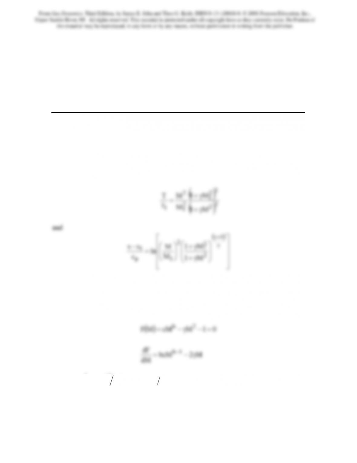
This is a companion to Example 10.2. In that problem the reference state is the same as
given here, however, γ = 1.3. To draw the Rayleigh line for the given reference state we
have
⎥
⎥
⎥
⎦
⎢
⎢
⎢
⎣
⎟
⎟
⎠
⎜
⎜
⎝
γ+
⎟
⎟
⎠
⎜
⎜
⎝
=
2
1
1p
1
M1
M
ln
c
It should be noted that the entropy change is zero for M = M1 and therefore at T = T1.
The second value is determined by setting the argument of the natural logarithm to 1 and
solving the nonlinear equation using the Newton-Raphson method. The function that is
solved and its derivative are
2b
where
(
)
()
12bandMM1c b
1
2
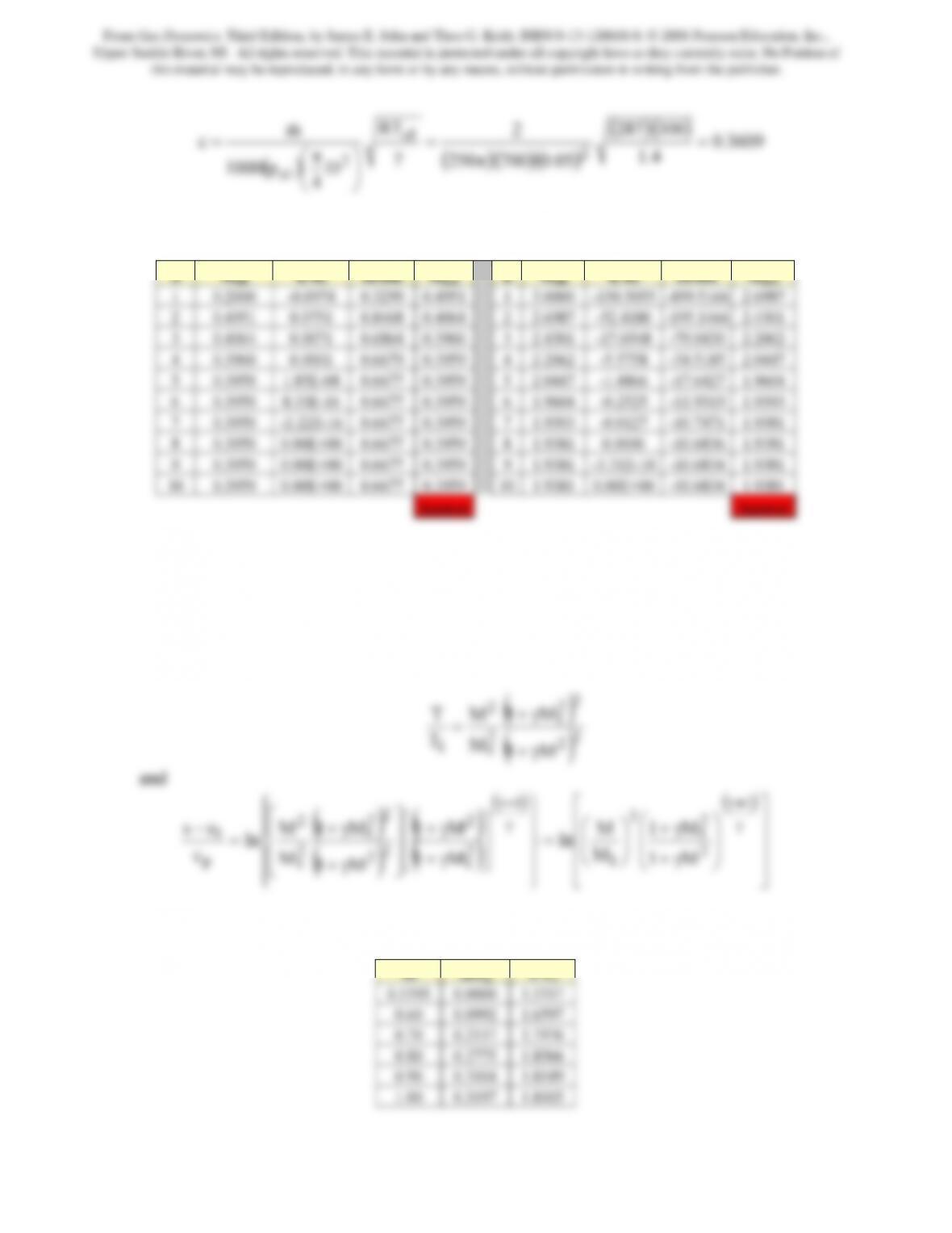
1+γγ=γ+= . For M1 = 3.0 and γ = 1.4 the solution
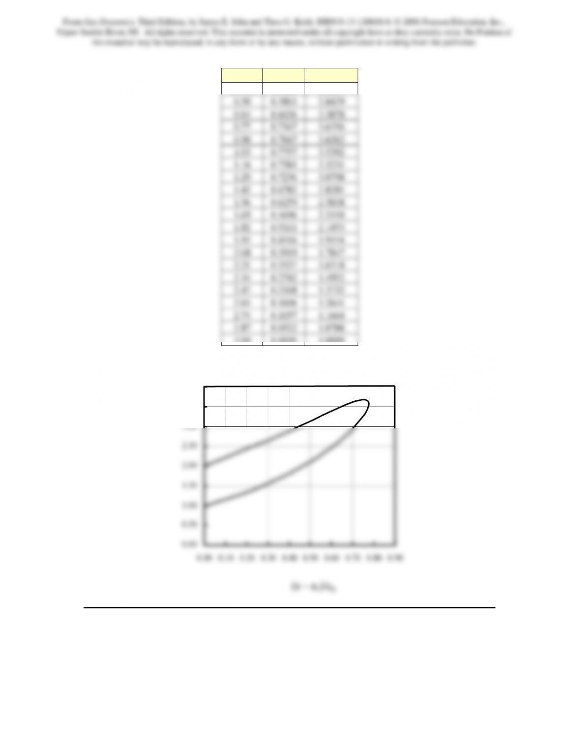
procedure yields M = 0.37307. The calculations to draw the Rayleigh line were
performed within a spreadsheet program and the results are contained in the following
table and figure
From Gas Dynamics, Third Edition, by James E. John and Theo G. Keith. ISBN 0-13-120668-0. © 2006 Pearson Education, Inc.,
Upper Saddle River, NJ. All rights reserved. This material is protected under all copyright laws as they currently exist. No Portion of
this material may be reproduced, in any form or by any means, without permission in writing from the publisher.
208
M ∆s/cp T/T1
0.3731 0.0000 2.0035
3.00 0.0000 1.0000
0.00
0.50
1.00
1.50
2.00
2.50
3.00
3.50
4.00
Problem 2. – Draw the T-s diagram for the flow of a gas with γ = 1.3 in a constant
diameter pipe with heat addition or loss. The reference Mach number, M1, for the flow is
4.0.
T/T1
From Gas Dynamics, Third Edition, by James E. John and Theo G. Keith. ISBN 0-13-120668-0. © 2006 Pearson Education, Inc.,
Upper Saddle River, NJ. All rights reserved. This material is protected under all copyright laws as they currently exist. No Portion of
this material may be reproduced, in any form or by any means, without permission in writing from the publisher.
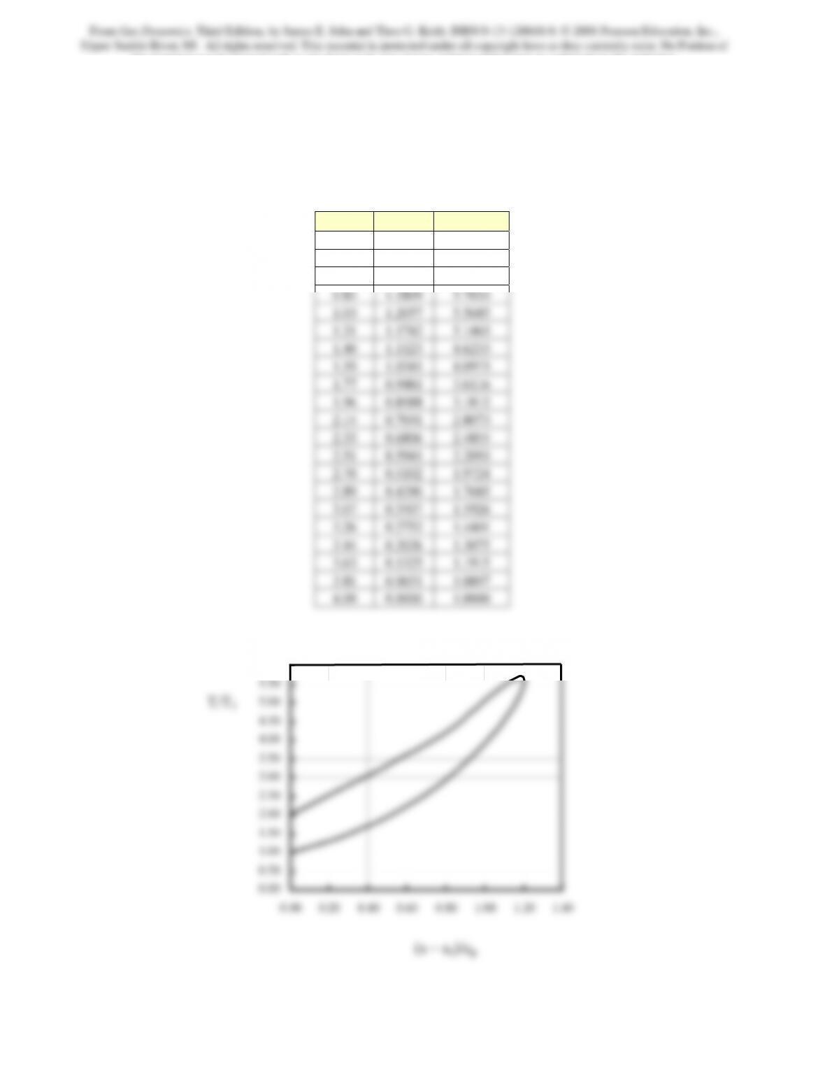
This is a companion to Example 10.2 and problem 1. In this problem the reference state
differs from these previous problems, however, γ = 1.3. For M1 = 4.0 and γ = 1.4 the
solution procedure yields M = 0.2864. The calculations to draw the Rayleigh line were
performed within a spreadsheet program and the results are contained in the following
table and figure
M ∆s/cp T/T1
0.2864 0.0000 1.9894
0.47 0.7287 3.9795
0.66 1.0527 5.2640
0.00
0.50
1.00
1.50
2.00
2.50
3.00
3.50
4.00
4.50
5.00
5.50
6.00
T/T1
From Gas Dynamics, Third Edition, by James E. John and Theo G. Keith. ISBN 0-13-120668-0. © 2006 Pearson Education, Inc.,
Upper Saddle River, NJ. All rights reserved. This material is protected under all copyright laws as they currently exist. No Portion of
this material may be reproduced, in any form or by any means, without permission in writing from the publisher.
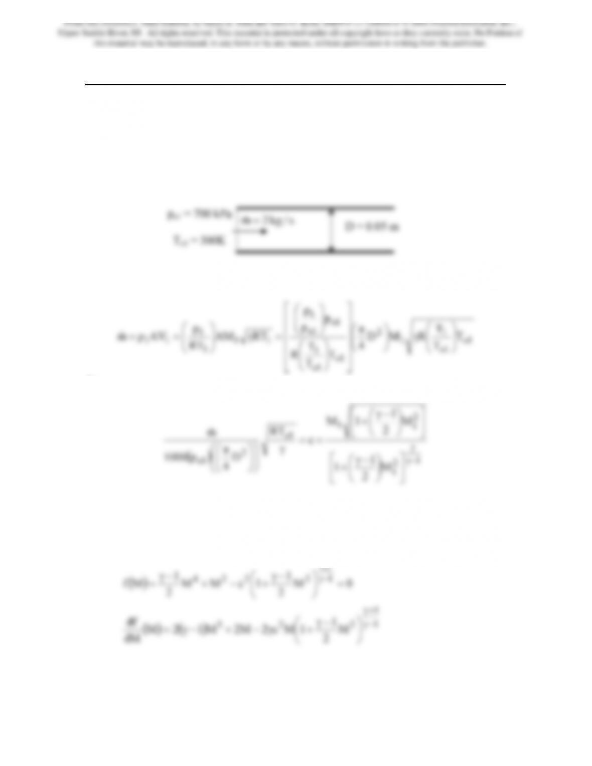
Problem 3. – Air (γ = 1.4 and R = 0.287 kJ/kg · K) flows in a constant-area duct of 5-cm
diameter at a rate of 2 kg/s. If the inlet stagnation pressure and temperature are,
respectively, 700 kPa and 300 K, plot T versus s for Rayleigh line flow. For the same
inlet conditions and mass flow rate, plot a T-s diagram for Fanno flow. From the points of
intersection of Rayleigh and Fanno lines, show the states on either side of a normal
shock. Assume the air to behave as a perfect gas with constant specific heats.
From Gas Dynamics, Third Edition, by James E. John and Theo G. Keith. ISBN 0-13-120668-0. © 2006 Pearson Education, Inc.,
Upper Saddle River, NJ. All rights reserved. This material is protected under all copyright laws as they currently exist. No Portion of
this material may be reproduced, in any form or by any means, without permission in writing from the publisher.
(
)
(
)
3609.0
4.1
300287
05.0700250
2
RT
m
c2
1o
2
=
π
=
γ
⎞
⎛π
=&
The calculations performed on a spreadsheet are as follows:
Thus, two possible Mach numbers are obtained-one subsonic and the other supersonic.
Since we seek to show that the intersection of the Rayleigh and Fanno lines correspond to
the states on either side of a normal shock, only the supersonic result needs to be
considered, i.e., the reference Mach number, M1 = 1.9381.
Rayleigh line: Following the procedure of Example 10.2 we may write
()
()
⎥
⎥
⎥
⎦
⎢
⎢
⎢
⎣
⎟
⎟
⎠
⎜
⎜
⎝
γ+
⎟
⎟
⎠
⎜
⎜
⎝
=
⎪
⎪
⎭
⎬
⎪
⎪
⎩
⎨
⎥
⎥
⎦
⎢
⎢
⎣
γ+
⎥
⎥
⎦
⎢
⎢
⎣
γ+
=
2
1
1
2
1
2
2
1
2
1
p
1
M1
M
ln
M1
M1
M
ln
c
Incorporating these into a spreadsheet program results in the following table of data
From Gas Dynamics, Third Edition, by James E. John and Theo G. Keith. ISBN 0-13-120668-0. © 2006 Pearson Education, Inc.,
Upper Saddle River, NJ. All rights reserved. This material is protected under all copyright laws as they currently exist. No Portion of
this material may be reproduced, in any form or by any means, without permission in writing from the publisher.
212
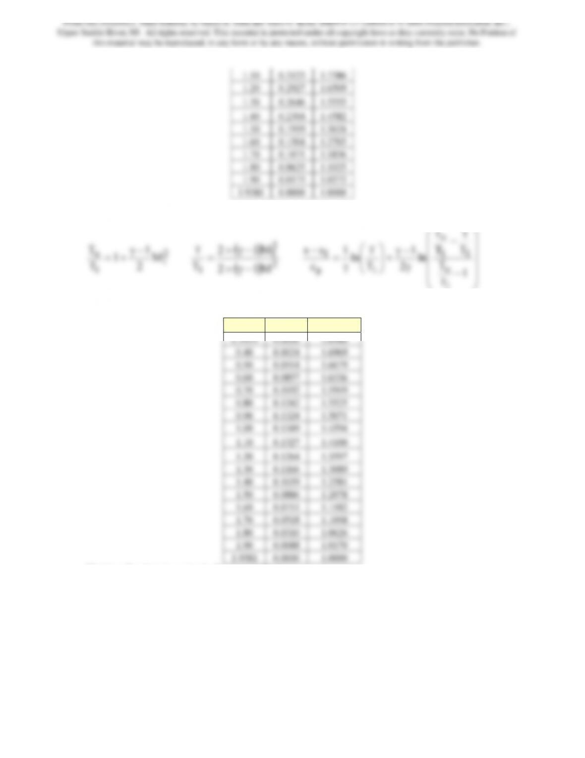
Fanno line: Following the procedure of Example 9.1 we may write
1
1
2
1
T
T−γ
+=
()
2
2
1M12
T
−γ+
=
⎟
⎟
⎟
⎠
⎞
⎜
⎜
⎜
⎝
⎛
−
−
γ
+
⎟
⎟
⎠
⎞
⎜
⎜
⎝
⎛
γ
=
1
T
T
T
T
ln
2
T
ln
c
1
o
o
1p
Incorporating these into a spreadsheet program results in the following table of data
M ∆s/cp T/T1
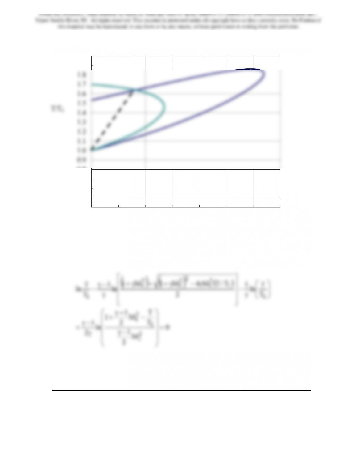
Plotting the data in a single figure results in
From Gas Dynamics, Third Edition, by James E. John and Theo G. Keith. ISBN 0-13-120668-0. © 2006 Pearson Education, Inc.,
Upper Saddle River, NJ. All rights reserved. This material is protected under all copyright laws as they currently exist. No Portion of
this material may be reproduced, in any form or by any means, without permission in writing from the publisher.
1.5
1.6
1.7
1.8
1.9
2.0
From Gas Dynamics, Third Edition, by James E. John and Theo G. Keith. ISBN 0-13-120668-0. © 2006 Pearson Education, Inc.,
Upper Saddle River, NJ. All rights reserved. This material is protected under all copyright laws as they currently exist. No Portion of
this material may be reproduced, in any form or by any means, without permission in writing from the publisher.
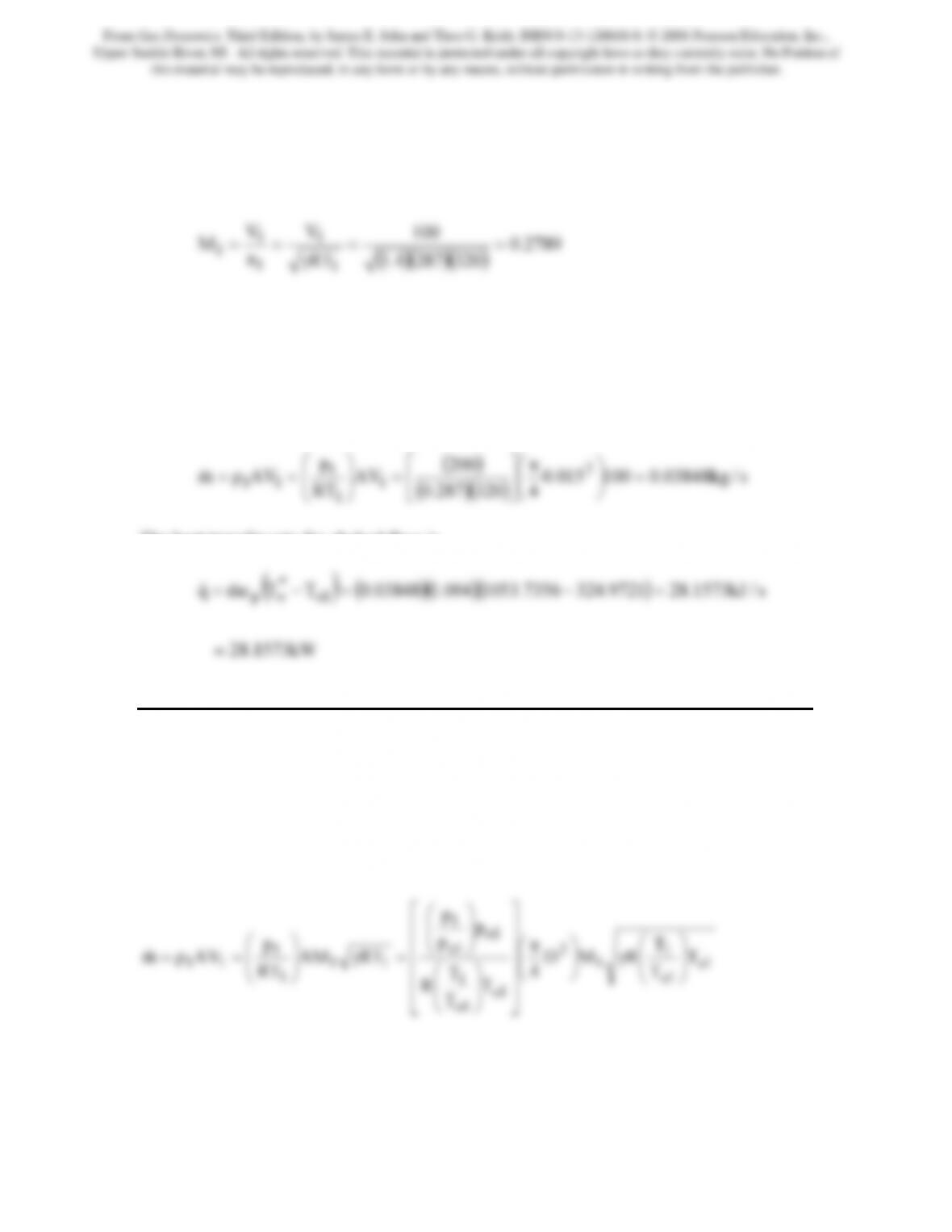
necessary to choke the duct. Assume Rayleigh line flow; express your answer in
kilowatts. Assume the air to behave as a perfect gas with constant specific heats.
The Mach number at the initial station is
()( )( )
3202874.1
RT
a
1
1
1==
γ
At this Mach number from the isentropic relation (T/To)1 = 0.9847. Thus, To1 =
T1/0.9847 = 320/0.9847 = 324.9721K. Now using the initial Mach number in the
Rayleigh relation we find that To1/To* = 0.3084. Hence, To* = 324.9721/0.3084 =
1053.7356K.
The flow rate is given by
(
)
()()
s/kg03848.0100015.0
4320287.0
200
AV
RT
p
AVρm2
1
1
1
11 =
⎟
⎠
⎞
⎜
⎝
⎛π
⎥
⎦
⎤
⎢
⎣
⎡
=
⎟
⎟
⎠
⎞
⎜
⎜
⎝
⎛
==
&
The heat transfer rate for choked flow is
Problem 5. – Air (γ = 1.4, R = 0.287 kJ/kg · K and cp = 1.004 kJ/ kg · K) flows in a
constant-area duct of 10 cm diameter at a rate of 0.5 kg/s. The inlet stagnation pressure is
100 kPa; inlet stagnation temperature is 35°C. Find the following:
(a) Two possible values of inlet Mach number.
(b) For each inlet Mach number of part (a), determine the heat addition rate in kilowatts
necessary to choke the duct.
From Gas Dynamics, Third Edition, by James E. John and Theo G. Keith. ISBN 0-13-120668-0. © 2006 Pearson Education, Inc.,
Upper Saddle River, NJ. All rights reserved. This material is protected under all copyright laws as they currently exist. No Portion of
this material may be reproduced, in any form or by any means, without permission in writing from the publisher.
215
1
2
1
2
1
1
1o
1
1
1o
1
1
2
1o
1
M
2
1
1
M
2
1
1M
1256.3
T
T
M
p
p
1256.3
T
100
p
p
−γ
γ
⎥
⎦
⎤
⎢
⎣
⎡⎟
⎠
⎞
⎜
⎝
⎛−γ
+
⎥
⎦
⎤
⎢
⎣
⎡⎟
⎠
⎞
⎜
⎝
⎛−γ
+
=
⎟
⎟
⎠
⎞
⎜
⎜
⎝
⎛
=
⎞
⎛
⎞
⎛π
⎥
⎥
⎤
⎢
⎢
⎡
⎟
⎟
⎠
⎞
⎜
⎜
⎝
⎛
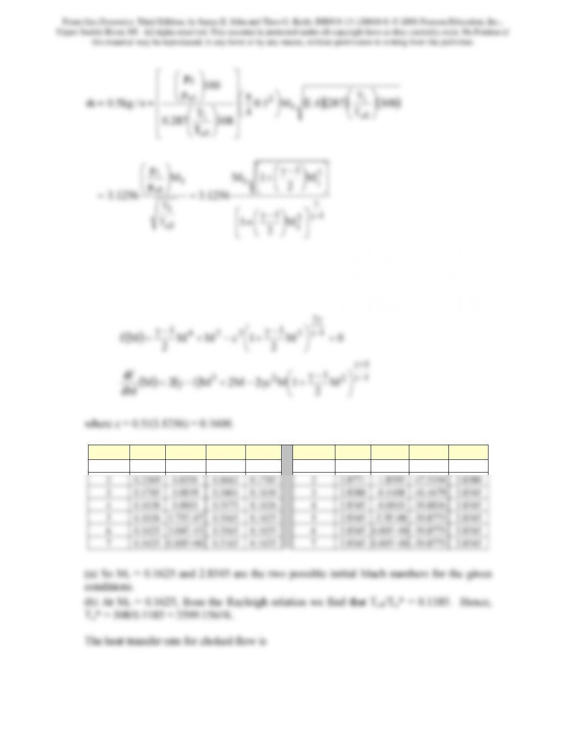
This is a nonlinear algebraic equation that can be solved by the Newton-Raphson method.
The following is a table that presents the iterations to determine the two Mach numbers
by this approach. The function that is to be solved to determine the Mach numbers and its
derivative are
1
1
2
2224 =
⎞
⎛−γ
−γ
γ
Iteration Mold f(M) df/dm Mnew Iteration Mold f(M) df/dm Mnew
1 0.4000 0.1332 0.8166 0.2369 1 3.0000 -9.3419 -76.0257 2.8771
From Gas Dynamics, Third Edition, by James E. John and Theo G. Keith. ISBN 0-13-120668-0. © 2006 Pearson Education, Inc.,
Upper Saddle River, NJ. All rights reserved. This material is protected under all copyright laws as they currently exist. No Portion of
this material may be reproduced, in any form or by any means, without permission in writing from the publisher.
(
)
()( )( )
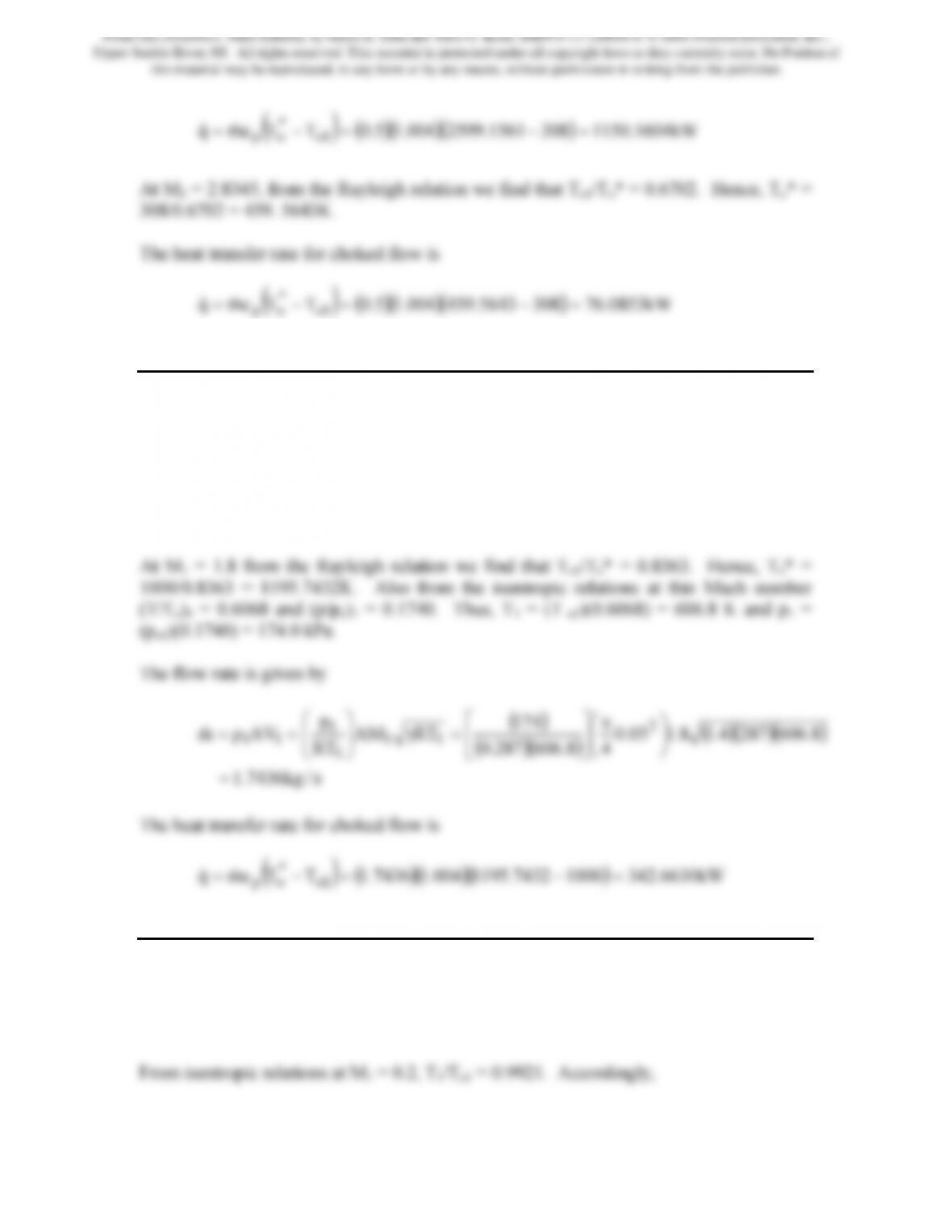
kW1604.11503081561.2599004.15.0TTcmq 1o
*
op =−=−= &&
At M1 = 2.8345, from the Rayleigh relation we find that To1/To* = 0.6702. Hence, To* =
308/0.6702 = 459. 5643K.
The heat transfer rate for choked flow is
(
)
()( )( )
kW0853.763085643.459004.15.0TTcmq 1o
*
op =−=−= &&
Problem 6. – A. supersonic flow at po = 1.0 MPa and To = 1000 K enters a 5 cm diameter
duct at Mach 1.8. Heat is added to the flow via a chemical reaction taking place inside the
duct. Determine the heat transfer rate in kilowatts necessary to choke the duct. Assume
the air (γ = 1.4, R = 0.287 kJ/kg · K and cp = 1.004 kJ/ kg · K) to behave as a perfect gas
with constant specific heats; neglect changes in the composition of the gas stream due to
the chemical reaction.
Problem 7. – Heat is added to airflow (γ = 1.4 and R = 0.287 kJ/kg · K) in a constant-area
duct at the rate of 30 kJ/m. If flow enters at Mach 0.20, T1= 300 K, and p1 = 100 kPa,
determine M(x), p(x), T(x), and po(x).
From Gas Dynamics, Third Edition, by James E. John and Theo G. Keith. ISBN 0-13-120668-0. © 2006 Pearson Education, Inc.,
Upper Saddle River, NJ. All rights reserved. This material is protected under all copyright laws as they currently exist. No Portion of
this material may be reproduced, in any form or by any means, without permission in writing from the publisher.
217
9921.0
1
T
T
1
1o
1o =
⎠
⎞
⎝
⎛
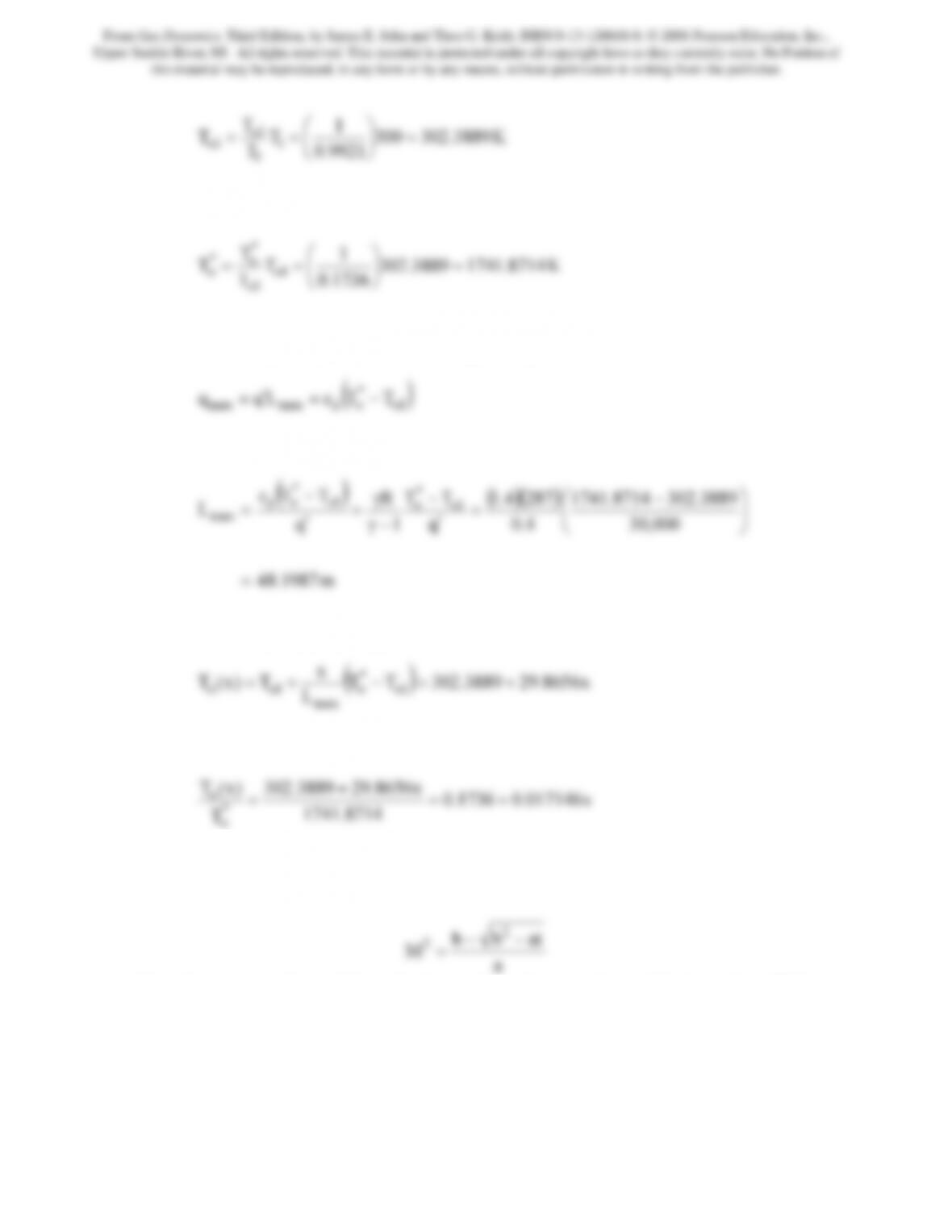
From the Rayleigh relations at M1 = 0.2, To1/T*o = 0.1736. Hence,
1736.0
T
1o
o=
⎠
⎝
The maximum length that the pipe may have without affecting the mass flow rate is
obtained when Toe = T*o. Therefore from Eq.(10.10),
1o
opmaxmax TTcLqq −=
Solving for the maximum length
m1987.48
=
The distribution of To(x) can also be determined from Eq.(10.10)
L
x
*
max
Hence,
8714.1741
T
*
o
Now for a given x, Eq.(10.14) may be used to determine M(x), i.e., letting t = To/To*,
b = 1 – γ(t − 1) and a = 1 + γ2(t − 1) we have
a
Note the − sign in front of the radical is used to obtain a subsonic Mach number. With
this Mach number it is an easy matter to obtain the static pressure and temperature
distributions from Eqs.(10.8) and (10.9), respectively. The stagnation pressure
distribution can be obtained from
From Gas Dynamics, Third Edition, by James E. John and Theo G. Keith. ISBN 0-13-120668-0. © 2006 Pearson Education, Inc.,
Upper Saddle River, NJ. All rights reserved. This material is protected under all copyright laws as they currently exist. No Portion of
this material may be reproduced, in any form or by any means, without permission in writing from the publisher.
218
oM
2
)x(p
γ
⎠
⎝
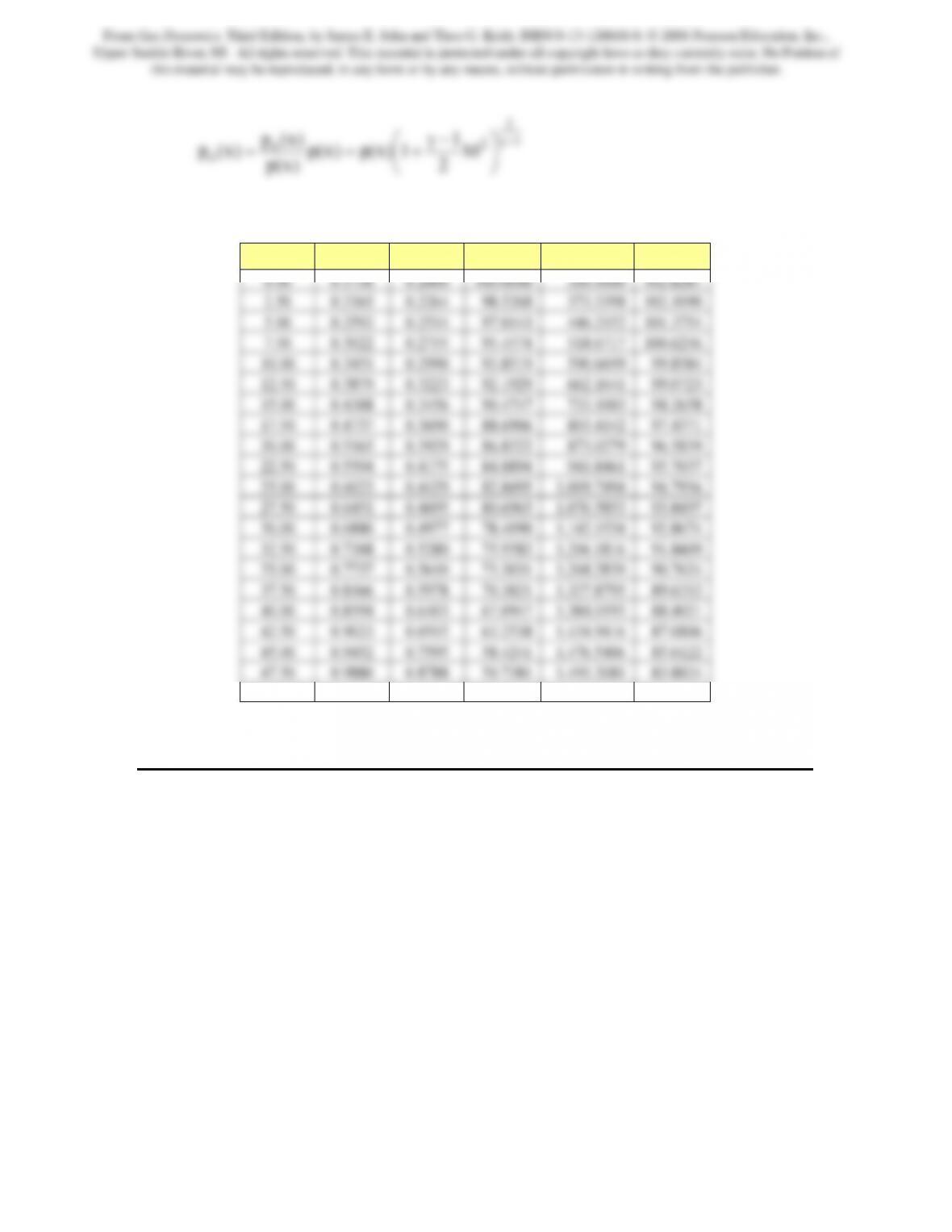
The following table contains the results obtained from a simple spreadsheet program
x To/To
* M p(x) T(x) po(x)
48.1987 1.0000 1.0000 44.0000 1,452.0000 83.2889
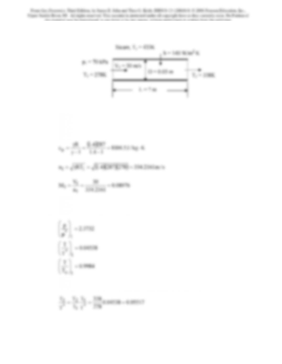
Problem 8. – An airstream (γ = 1.4 and R = 0.287 kJ/kg · K) passing through a 5-cm-
diameter, thin-walled tube is to be heated by high-pressure steam condensing on the outer
surface of the tube at 160°C. The overall heat transfer coefficient between steam and air
can be assumed to be 140 W/m2·K, with the air entering at 30 m/s, 70 kPa, and 5°C. The
air is to be heated to 65°C. Determine the tube length required. Assuming Rayleigh line
flow, calculate the static pressure change due to heat addition. Also, for the same inlet
conditions, calculate the pressure drop due to friction, assuming Fanno flow in the duct
with f = 0.018. To obtain an approximation to the overall pressure drop in this heat
exchanger, add the two results.
From Gas Dynamics, Third Edition, by James E. John and Theo G. Keith. ISBN 0-13-120668-0. © 2006 Pearson Education, Inc.,
Upper Saddle River, NJ. All rights reserved. This material is protected under all copyright laws as they currently exist. No Portion of
this material may be reproduced, in any form or by any means, without permission in writing from the publisher.
From Gas Dynamics, Third Edition, by James E. John and Theo G. Keith. ISBN 0-13-120668-0. © 2006 Pearson Education, Inc.,
Upper Saddle River, NJ. All rights reserved. This material is protected under all copyright laws as they currently exist. No Portion of
this material may be reproduced, in any form or by any means, without permission in writing from the publisher.
220
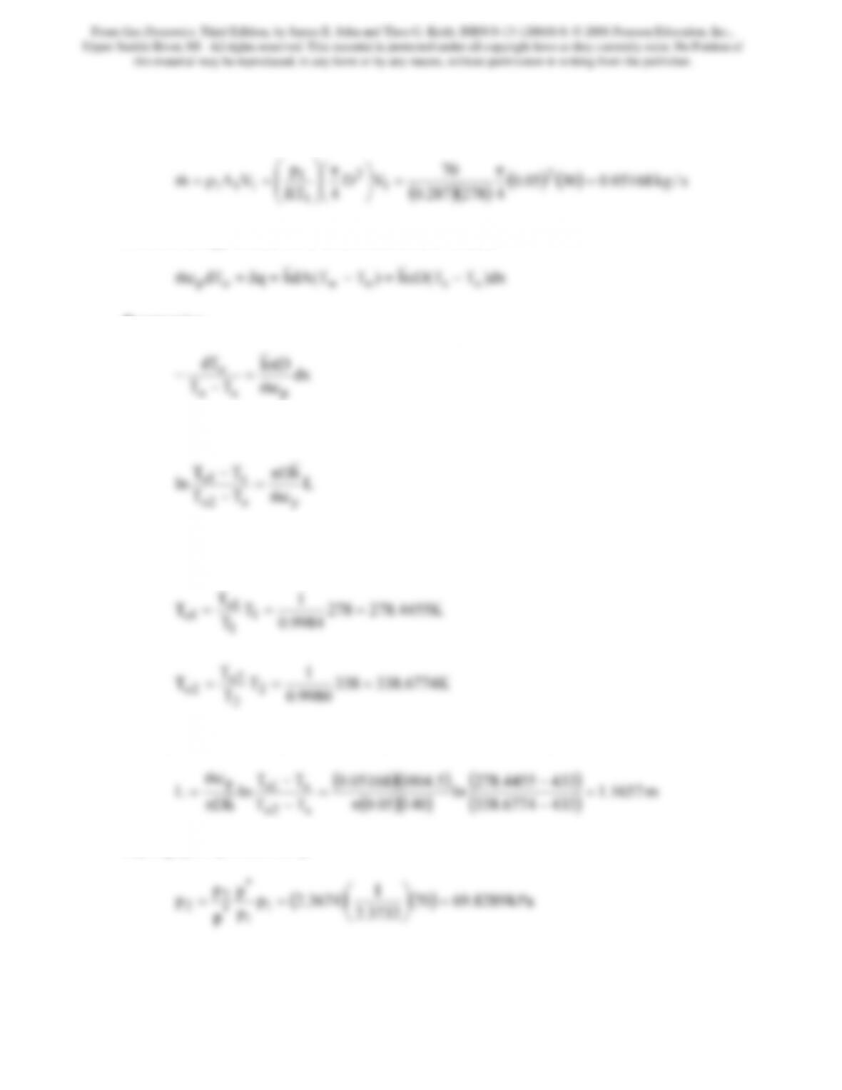
The mass flow rate in the pipe may be computed as follows
()()
()()
s/kg05168.03005.0
4278287.0
70
VD
4RT
p
VAm 2
1
2
1
1
111 =
π
=
⎟
⎠
⎞
⎜
⎝
⎛π
⎟
⎟
⎠
⎞
⎜
⎜
⎝
⎛
=ρ=
&
From an energy balance on a differential control volume
Rearranging
cm
Dh
TT
dT
pso
o
&
π
−
Integrating along the length of the pipe gives
L
cm
TT
ln
ps2o
s1o
&
=
−
To1 and To2 are computed from the given static temperatures and the values of the static
to total temperature ratios determined above
K6774.338338
9980.0
1
T
T
T
T
K4455.278278
9984.0
1
T
T
T
T
2
2
2o
2o
1
1
1o
1o
===
===
Solving for the pipe length and inserting the various parameters gives
()()
()
4336774.338
14005.0
TT
hD
s2o
−
π
−
π
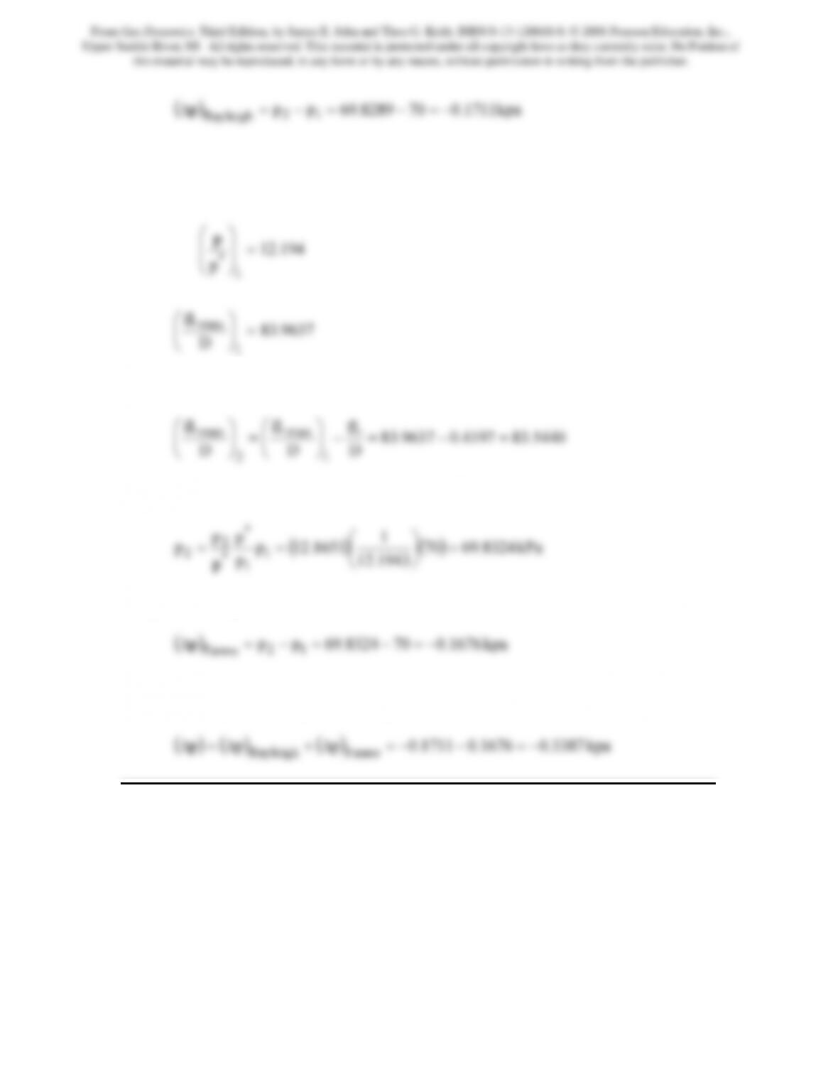
Rayleigh flow pressure drop
3732.2
p
p
1
*
2=
⎠
⎝
The pressure drop is therefore,
From Gas Dynamics, Third Edition, by James E. John and Theo G. Keith. ISBN 0-13-120668-0. © 2006 Pearson Education, Inc.,
Upper Saddle River, NJ. All rights reserved. This material is protected under all copyright laws as they currently exist. No Portion of
this material may be reproduced, in any form or by any means, without permission in writing from the publisher.
221
Rayleigh
Fanno flow pressure drop
At M1 = 0.08976 from the Fanno relations
9637.83
D
fL
1
max
=
⎟
⎠
⎞
⎜
⎝
⎛
Inserting parameters gives fL/D =(0.018)(1.1657)/0.05 = 0.4197. Therefore,
5440.834197.09637.83
D
fL
D
fL
D
fL
1
max
2
max =−=−
⎟
⎠
⎞
⎜
⎝
⎛
=
⎟
⎠
⎞
⎜
⎝
⎛
From which we find M2 = 0.08998 and in turn (p/p*)2 = 12.1651. Thus,
1943.12
p
p
1
*
2=
⎠
⎝
The pressure drop is therefore,
Fanno
The combined pressure drop if added together is
Problem 9. – Air (γ = 1.4 and R = 0.287 kJ/kg · K) enters a turbojet combustion chamber
at 400 K and 200 kPa, with a temperature after combustion of 1000 K. If the heating
value of the fuel is 48,000 kJ/kg, determine the required fuel-air ratio (on a mass basis).
Assume Rayleigh line flow in the combustion chamber. What fuel-air ratio would be
required to choke the combustion chamber? The inlet velocity is 35 m/s.
The air is treated as a perfect gas, so
From Gas Dynamics, Third Edition, by James E. John and Theo G. Keith. ISBN 0-13-120668-0. © 2006 Pearson Education, Inc.,
Upper Saddle River, NJ. All rights reserved. This material is protected under all copyright laws as they currently exist. No Portion of
this material may be reproduced, in any form or by any means, without permission in writing from the publisher.