Fluid Mechanics, 6th Ed. Kundu, Cohen, and Dowling
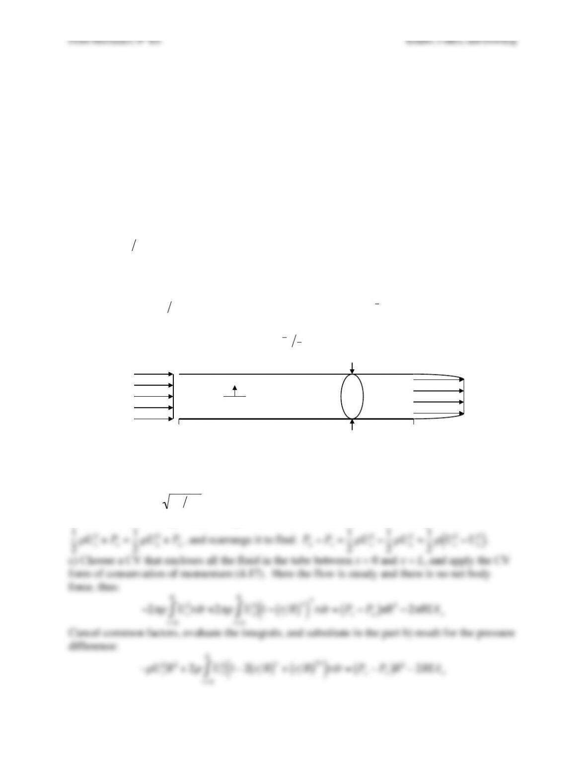
Exercise 4.17. Consider how pressure gradients and skin friction develop in an empty wind
tunnel or water tunnel test section when the flow is incompressible. Here the fluid has viscosity
µ
and density
ρ
, and flows into a horizontal cylindrical pipe of length L with radius R at a uniform
horizontal velocity Uo. The inlet of the pipe lies at x = 0. Boundary layer growth on the pipe’s
walls induces the horizontal velocity on the pipe’s centerline to be UL at x = L; however, the
pipe-wall boundary layer thickness remains much smaller than R. Here, L/R is of order 10, and
ρ
UoR/
µ
>> 1. The radial coordinate from the pipe centerline is r.
a) Determine the displacement thickness,
δ
L
*
, of the boundary layer at x = L in terms of Uo, UL ,
and R. Assume that the boundary layer displacement thickness is zero at x = 0. [The boundary
layer displacement thickness,
δ
*, is the thickness of the zero-flow-speed layer that displaces the
outer flow by the same amount as the actual boundary layer. For a boundary layer velocity
profile u(y) with y = wall-normal coordinate and U = outer flow velocity,
δ
* is defined by:
δ
*=1−u U
( )
( )
0
∞
∫dy
.]
b) Determine the pressure difference, ΔP = PL – Po, between the ends of the pipe in terms of
ρ
,
Uo, and UL.
c) Assume the horizontal velocity profile at the outlet of the pipe can be approximated by:
u(r,x=L)=UL1−r R
( )
n
( )
and estimate average skin friction,
τ
w
, on the inside of the pipe
between x = 0 and x = L in terms of
ρ
, Uo, UL, R, L, and n.
d) Calculate the skin friction coefficient,
cf=
τ
w
1
2
ρ
Uo
2
, when Uo = 20.0 m/s, UL = 20.5 m/s, R =
1.5 m, L = 12 m, n = 80, and the fluid is water, i.e.
ρ
= 103 kg/m3.
Solution 4.17. a) Apply the principle of conservation of mass. The effective flow area will be
π
R2
at the inlet (x = 0), but will be
π
R−
δ
L
*
( )
2
at the outlet (x = L):
Uo
π
R2=UL
π
R−
δ
L
*
( )
2
.
Solve for
δ
L
*=R1−UoUL
( )
.
b) Start from the steady Bernoulli equation (4.19) for horizontal flow (no body force):
1
2
ρ
Uo
2+P
o=1
2
ρ
UL
2+P
L
, and rearrange it to find:
P
L−P
o=1
2
ρ
Uo
2−1
2
ρ
UL
2=1
2
ρ
Uo
2−UL
2
( )
.
c) Choose a CV that encloses all the fluid in the tube between x = 0 and x = L, and apply the CV
form of conservation of momentum (4.17). Here the flow is steady and there is no net body
force, thus:
−2
πρ
Uo
2rdr +
r=0
R
∫2
πρ
UL
21−r R
( )
n
( )
2
rdr =P
o−P
L
( )
r=0
R
∫
π
R2−2
π
RL
τ
w
Cancel common factors, evaluate the integrals, and substitute in the part b) result for the pressure
difference:
−
ρ
Uo
2R2+2
ρ
UL
21−2r R
( )
n+r R
( )
2n
( )
rdr =P
o−P
L
( )
r=0
R
∫R2−2RL
τ
w
x = 0!x = L!
2R!
Uo!UL!
r!
Fluid Mechanics, 6th Ed. Kundu, Cohen, and Dowling
Divide by
ρ
R2 and collect terms:
−Uo
2+UL
21−4
n+2+1
n+1
#
$
% &
‘
( =1
2
UL
2−Uo
2
( )
−2L
τ
w
ρ
R
1
2−4
n+2+1
n+1
#
$
% &
‘
(
UL
2−1
2
Uo
2=−2L
τ
w
ρ
R
Solve for the average shear stress:
τ
w=
ρ
R
4L
Uo
2−1−8
n+2+2
n+1
%
&
‘ (
)
*
UL
2
+
,
–
.
/
0
d) Use the result of part c) to find:
cf=2
τ
w
ρ
Uo
2=R
2L
1−1−8
n+2+2
n+1
%
&
‘ (
)
*
UL
2
Uo
2
+
,
–
.
/
0
. Evaluate:
cf=1.5m
2(12m)1−1−8
82 +2
81
#
$
% &
‘
( 20.5
20.0
#
$
% &
‘
(
2
)
*
+
,
–
.
= 0.00162
The numbers provided here are approximately applicable to the William B. Morgan Large
Cavitation Channel in Memphis, Tennessee, the world’s largest low-turbulence water tunnel.
Fluid Mechanics, 6th Ed. Kundu, Cohen, and Dowling
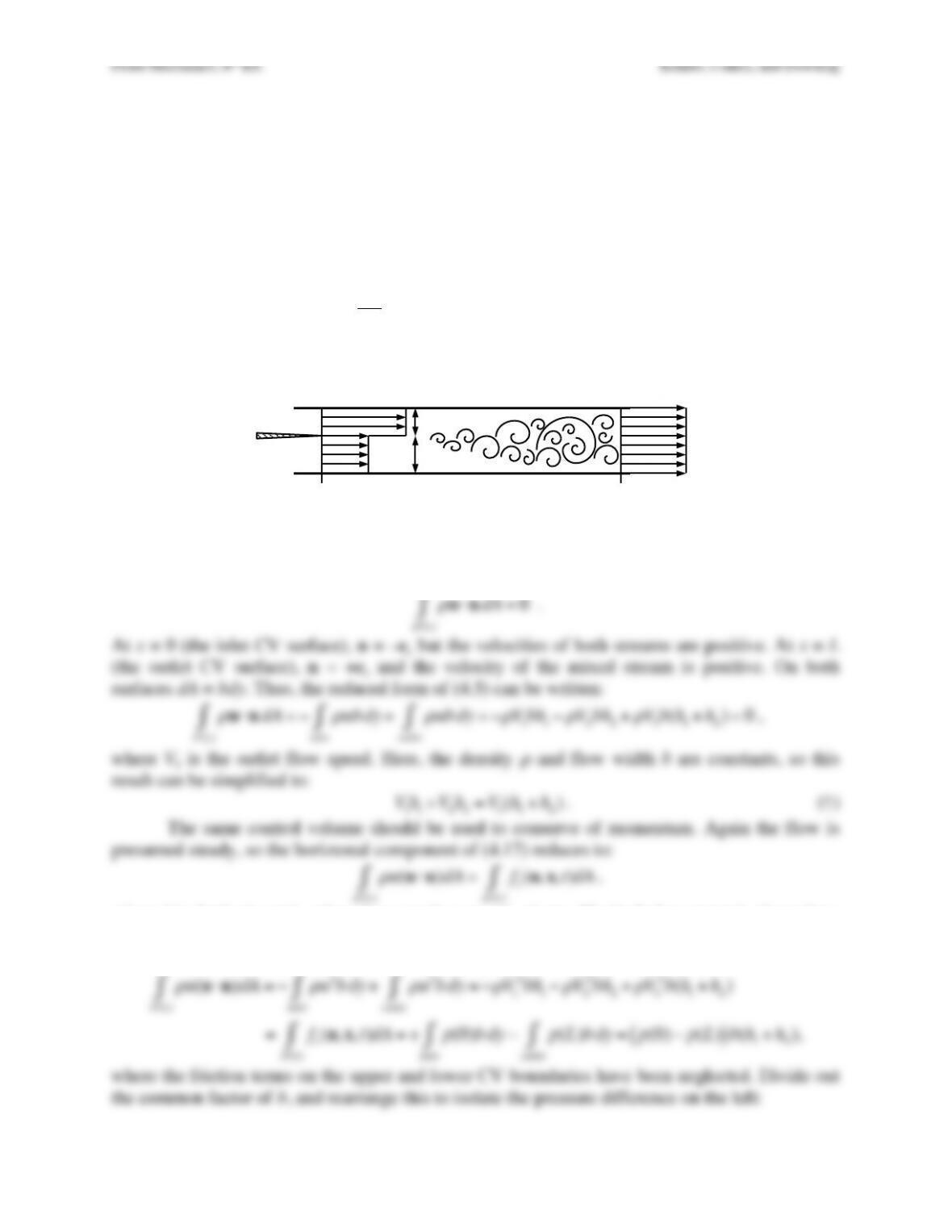
Exercise 4.18. An acid solution with density
ρ
flows horizontally into a mixing chamber at
speed V1 at x = 0 where it meets a buffer solution with the same density moving at speed V2. The
inlet flow layer thicknesses are h1 and h2 as shown, the mixer chamber height is constant at h1 +
h2, and the chamber width into the page is b. Assume steady uniform flow across the two inlets
and the outlet. Ignore fluid friction on the interior surfaces of the mixing chamber for parts a) and
b).
a) By conserving mass and momentum in a suitable control volume, determine the pressure
difference, Δp = p(L) – p(0), between the outlet (x = L) and inlet (x = 0) of the mixing chamber in
terms of V1, V2, h1, h2, and
ρ
. Do not use the Bernoulli equation.
b) Is the pressure at the outlet higher or lower than that at the inlet when V1 ≠ V2?
c) Explain how your answer to a) would be modified by friction on the interior surfaces of the
mixing chamber.
Solution 4.18. a) Choose a stationary control volume (b = 0) that captures the fluid between x =
0 and x = L. Here the inflows and outflows are presumed steady. Thus, conservation of mass
from (4.5) reduces to:
ρ
u⋅ndA =0
A*(t)
∫
.
At x = 0 (the inlet CV surface), n = –ex but the velocities of both streams are positive. At x = L
(the outlet CV surface), n = +ex and the velocity of the mixed stream is positive. On both
surfaces dA = bdy. Thus, the reduced form of (4.5) can be written:
ρ
u⋅ndA =−
ρ
ub dy
inlet
∫+
ρ
ub dy
outlet
∫=−
ρ
V
1bh1−
ρ
V2bh2+
ρ
V3b(h1+h2)=0
A*(t)
∫
,
where V3 is the outlet flow speed. Here, the density
ρ
and flow width b are constants, so this
result can be simplified to:
V
1h
1+V2h2=V3(h
1+h2)
. (†)
The same control volume should be used to conserve of momentum. Again the flow is
presumed steady, so the horiztonal component of (4.17) reduces to:
ρ
u
A*(t)
∫(u⋅n)dA =fx(n,x,t)
A*(t)
∫dA
,
where fx is the horizontal surface force on the control volume. The body force term is absent here
because gravity acts vertially. As for conservation of mass with this control volume, only the
inflow and outflow surfaces contribute. Evaluating the reduced form of (4.17) produces:
ρ
u
A*(t)
∫(u⋅n)dA =−
ρ
u2b dy
inlet
∫+
ρ
u2b dy
outlet
∫=−
ρ
V
1
2bh1−
ρ
V2
2bh2+
ρ
V3
2b(h1+h2)
=fx(n,x,t)
A*(t)
∫dA = + p(0)b dy
inlet
∫−p(L)b dy
outlet
∫=p(0) −p(L)
( )
b(h
1+h2),
where the friction terms on the upper and lower CV boundaries have been neglected. Divide out
the common factor of b, and rearrange this to isolate the pressure difference on the left:
h1!
h2!
V1!
V2!
x = 0!x = L!
Fluid Mechanics, 6th Ed. Kundu, Cohen, and Dowling
Fluid Mechanics, 6th Ed. Kundu, Cohen, and Dowling
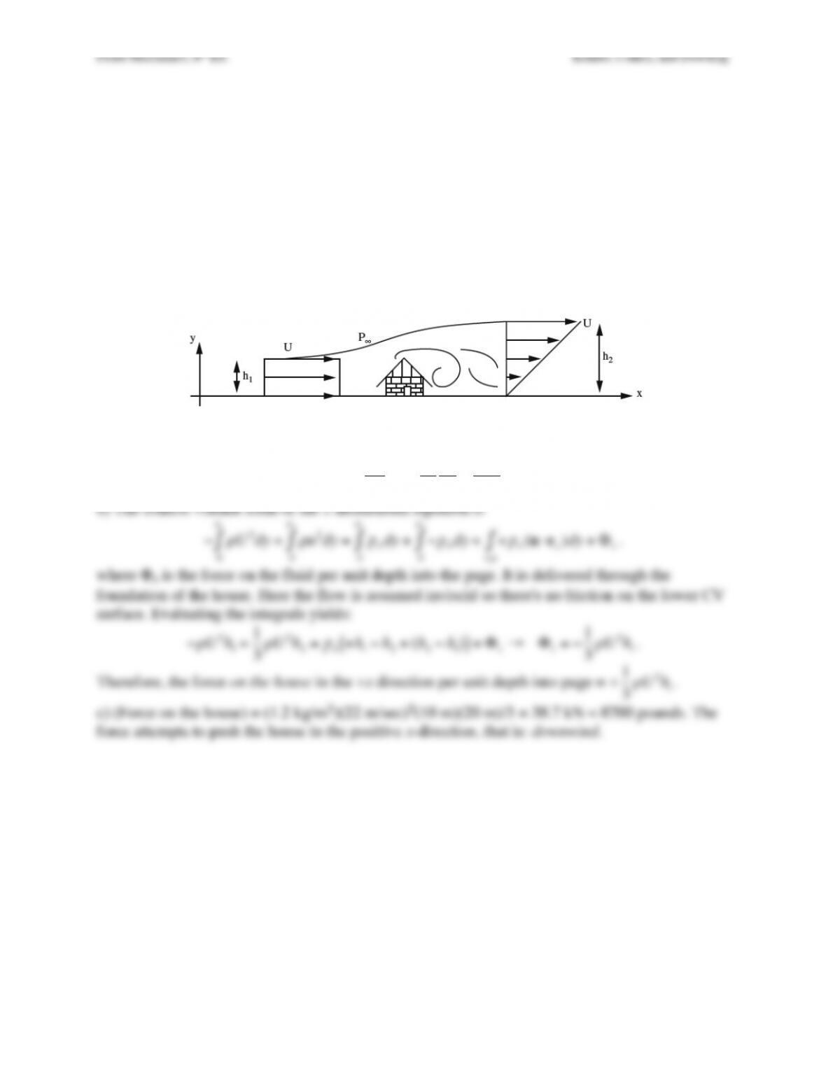
Exercise 4.19. Consider the situation depicted below. Wind strikes the side of a simple
residential structure and is deflected up over the top of the structure. Assume the following: two-
dimensional steady inviscid constant-density flow, uniform upstream velocity profile, linear
gradient in the downstream velocity profile (velocity U at the upper boundary and zero velocity
at the lower boundary as shown), no flow through the upper boundary of the control volume, and
constant pressure on the upper boundary of the control volume. Using the control volume shown:
a) Determine h2 in terms of U and h1, and
b) Determine the direction and magnitude of the horizontal force on the house per unit depth into
the page in terms of the fluid density
ρ
, the upstream velocity U, and the height of the house h1.
c) Evaluate the magnitude of the force for a house that is 10 m tall and 20 m long in wind of 22
m/sec (approximately 50 miles per hour).
Solution 4.19. 3. a) Use the control volume formulation of the continuity equation to find that:
Uh1=u(y)dy
0
h2
∫=Uy
h2
dy
0
h2
∫=U
h2
h2
2
2=Uh2
2
→ h2 = 2h1.
b) The control volume form of the x-momentum equation is
Fluid Mechanics, 6th Ed. Kundu, Cohen, and Dowling
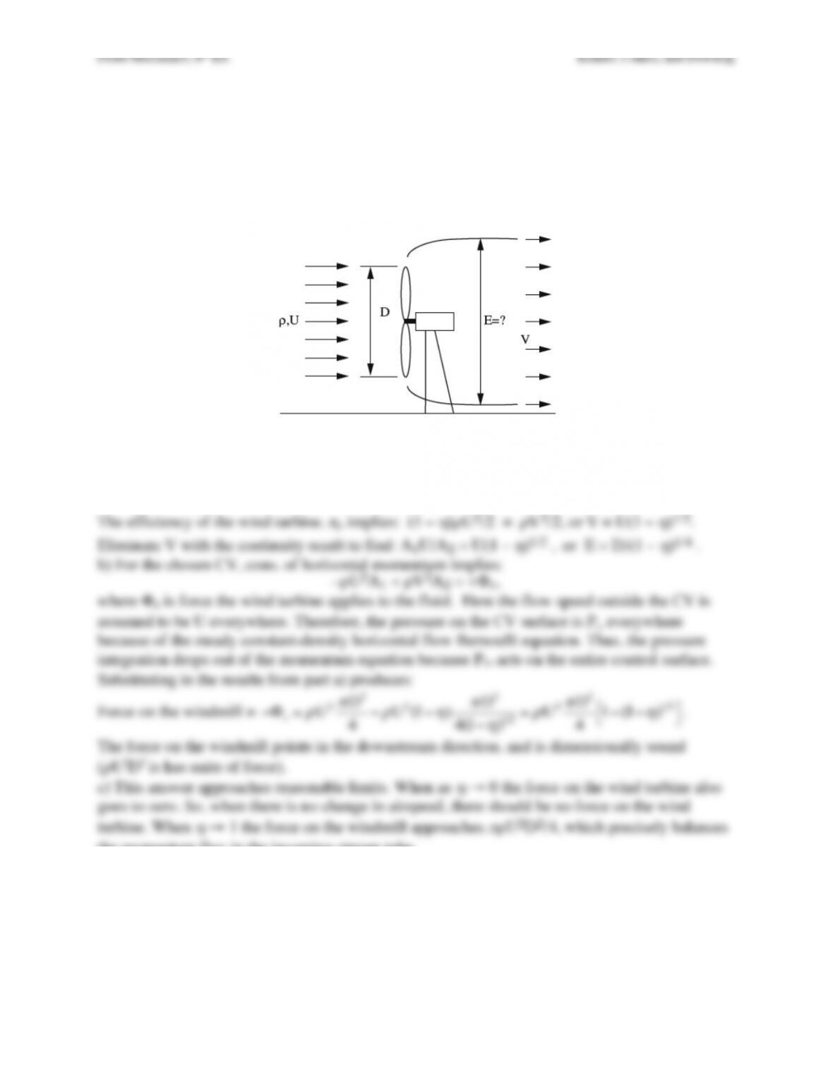
Exercise 4.20. A large wind turbine with diameter D extracts a fraction
η
of the kinetic energy
from the airstream (density =
ρ
= constant) that impinges on it with velocity U.
a) What is the diameter of the wake zone, E, downstream of the windmill?
b) Determine the magnitude and direction of the force on the windmill in terms of
ρ
, U, D, and
η
.
c) Does your answer approach reasonable limits as
η
→ 0 &
η
→ 1?
Solution 4.20. Place a control volume around the stream tube that hits the windmill with vertical
inflow-outflow surfaces well upstream and downstream of the wind turbine.
a) For ρ = const, the volume flux in the stream tube must be constant. Therefore: V = A1U/A2.
The efficiency of the wind turbine, η, implies: (1 –
η
)
ρ
U2/2 =
ρ
V2/2, or V = U(1 –
η
)1/2.
the momentum flux in the incoming stream tube.
Fluid Mechanics, 6th Ed. Kundu, Cohen, and Dowling
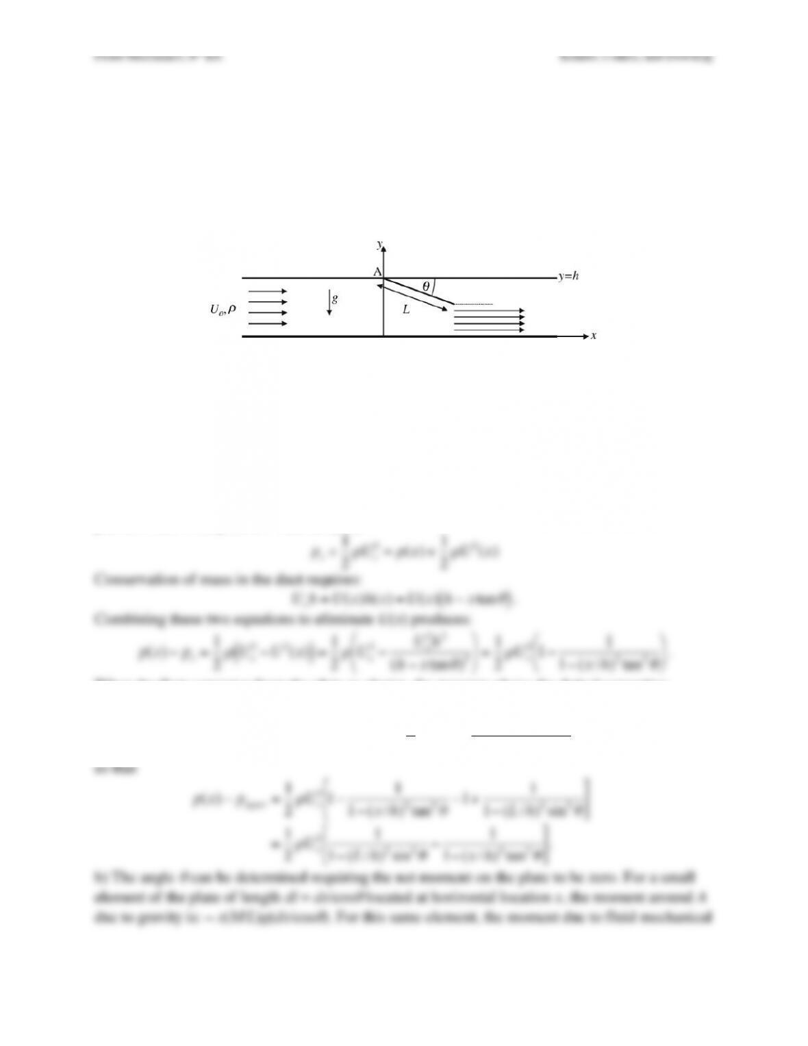
Exercise 4.21. An incompressible fluid of density
ρ
flows through a horizontal rectangular duct
of height h and width b. A uniform flat plate of length L and width b attached to the top of the
duct at point A is deflected to an angle
θ
as shown.
a) Estimate the pressure difference between the upper and lower sides of the plate in terms of x,
ρ
, Uo, h, L and
θ
when the flow separates cleanly from the tip of the plate.
b) If the plate has mass M and can rotate freely about the hinge at A, determine a formula for the
angle
θ
in terms of the other parameters. You may leave your answer in terms of an integral.
Solution 4.21. a) The question says to estimate the pressure difference. Thus, reasonable
simplifying assumptions should be acceptable. The first of these is to ignore the two-dimensional
character of the flow field and assume uniform horizontal flow at each x location. The second is
to assume steady flow.
So, for the conditions stated (incompressible), the pressure difference between the upper
and lower side the plate can be estimated from the Bernoulli equation applied between a mid-
duct point comfortably upstream of the plate, where the flow speed is Uo and the pressure is po,
and a location x that is connected to the first point by a streamline, where the flow speed and
pressure below the plate are U(x) and p(x).
po+1
2
ρ
Uo
2=p(x)+1
2
ρ
U2(x)
Conservation of mass in the duct requires:
Uoh=U(x)h(x)=U(x)h−xtan
θ
( )
.
Combining these two equations to eliminate U(x) produces:
p(x)−po=1
2
ρ
Uo
2−U2(x)
( )
=1
2
ρ
Uo
2−Uo
2h2
(h−xtan
θ
)2
%
&
‘
(
)
* =1
2
ρ
Uo
21−1
1−(x/h)2tan2
θ
%
&
‘ (
)
*
.
When the flow separates from the plate as shown, the pressure above the dotted separating
streamline will be the same as that below it. This pressure is
pupper =p(x=Lcos
θ
)−po=1
2
ρ
Uo
21−1
1−(L/h)2sin2
θ
%
&
‘ (
)
*
,
so that
Fluid Mechanics, 6th Ed. Kundu, Cohen, and Dowling
Fluid Mechanics, 6th Ed. Kundu, Cohen, and Dowling
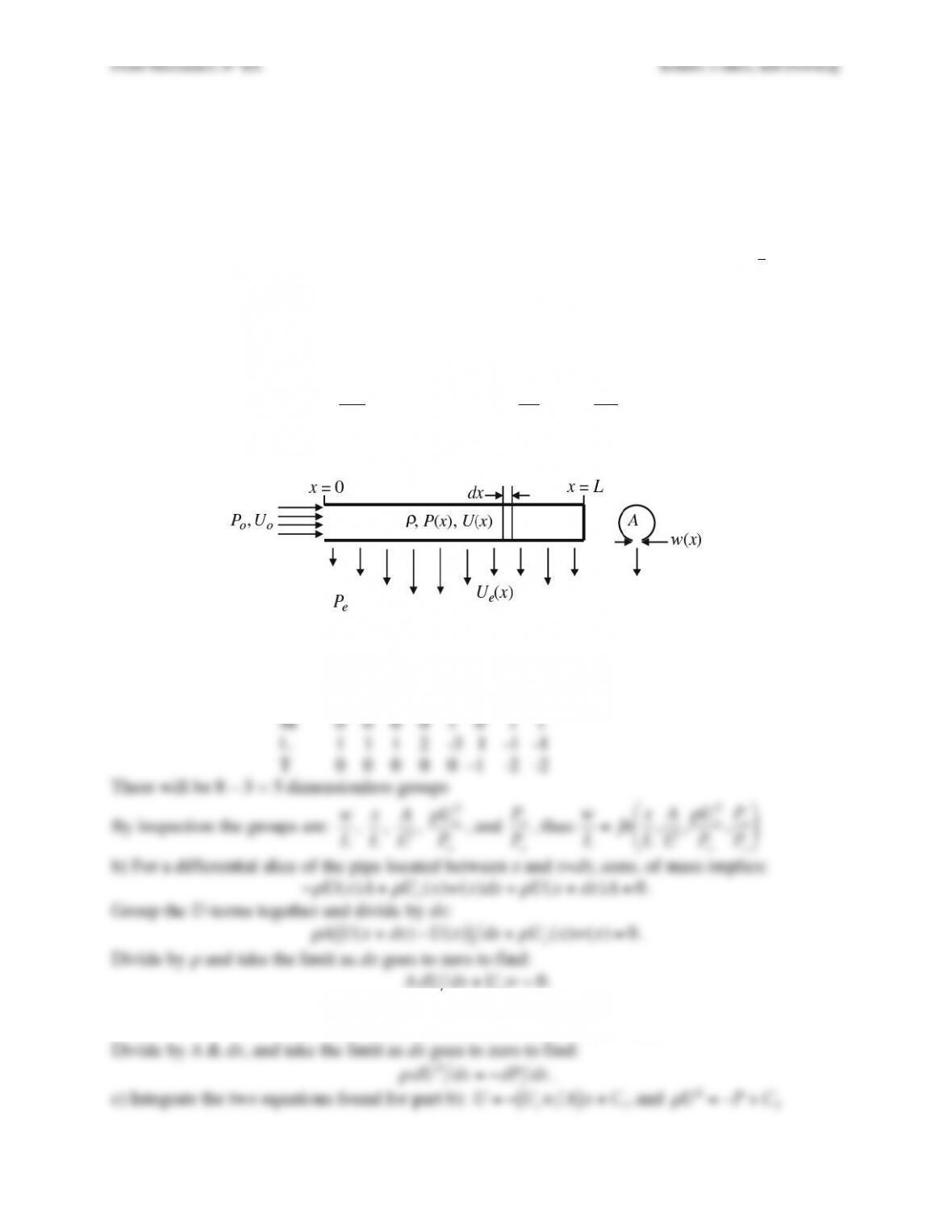
Exercise 4.22 A pipe of length L and cross sectional area A is to be used as a fluid distribution
manifold that expels a steady uniform volume flux per unit length of an incompressible liquid
from x = 0 to x = L. The liquid has density
ρ
, and is to be expelled from the pipe through a slot of
varying width, w(x). The goal of this problem is to determine w(x) in terms of the other
parameters of the problem. The pipe-inlet pressure and liquid velocity at x = 0 are Po and Uo,
respectively, and the pressure outside the pipe is Pe. If P(x) denotes the pressure on the inside of
the pipe, then the liquid velocity through the slot Ue is determined from:
P(x)−P
e=1
2
ρ
Ue
2
. For
this problem assume that the expelled liquid exits the pipe perpendicular to the pipe’s axis, and
note that wUe = const. = UoA/L, even though w and Ue both depend on x.
a) Formulate a dimensionless scaling law for w in terms of x, L, A,
ρ
, Uo, Po, and Pe.
b) Ignore the effects of viscosity, assume all profiles through the cross section of the pipe are
uniform, and use a suitable differential-control-volume analysis to show that:
AdU
dx +wUe=0
, and
ρ
d
dx
U2=−dP
dx
.
c) Use these equations and the relationships stated above to determine w(x) in terms of x, L, A,
ρ
,
Uo, Po, and Pe. Is the slot wider at x = 0 or at x = L?
Solution 4.22. a) Create the parameter matrix.
w x L A
ρ
Uo Po Pe
–––––––––––––––––––––––––––––
M 0 0 0 0 1 0 1 1
Using the same CV conserv horizontal momentum
−
ρ
U2(x)A+
ρ
U2(x+dx)A=P(x)A−P(x+dx)A
Divide by A & dx, and take the limit as dx goes to zero to find:
Fluid Mechanics, 6th Ed. Kundu, Cohen, and Dowling
Fluid Mechanics, 6th Ed. Kundu, Cohen, and Dowling
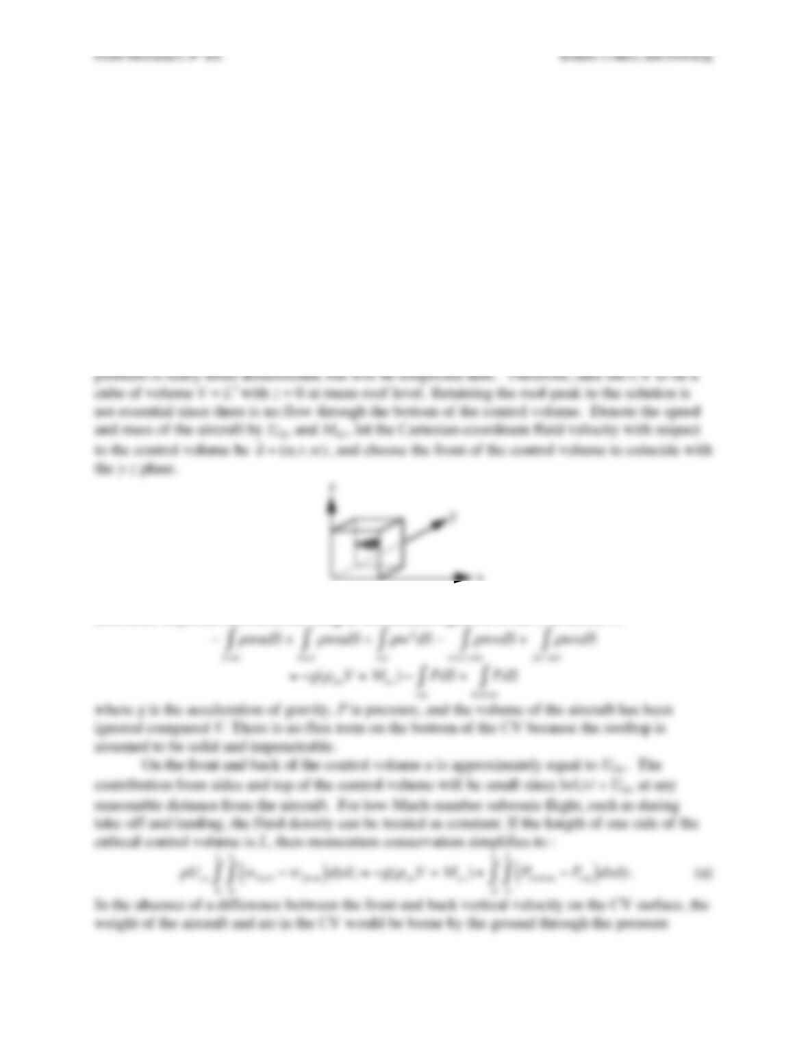
Exercise 4.23. The take-off mass of a Boeing 747-400 may be as high as 400,000 kg. An Airbus
A380 may be even heavier. Using a control volume (CV) that comfortably encloses the aircraft,
explain why such large aircraft do not crush houses or people when they fly low overhead. Of
course, the aircraft’s wings generate lift but they are entirely contained within the CV and do not
coincide with any of the CV’s surfaces; thus merely stating the lift balances weight is not a
satisfactory explanation. Given that the CV’s vertical body-force term,
−g
ρ
dV
CV
∫
, will exceed
4×10⁶ N when the airplane and air in the CV’s interior are included, your answer should instead
specify which of the CV’s surface forces or surface fluxes carries the signature of a large
aircraft’s impressive weight.
Solution 4.23. Assume that the airplane is in steady level flight so that the flow is steady in the
frame of reference of the airplane. Therefore, choose a frame of reference attached to the
airplane and select a control volume (CV) that comfortably encloses the aircraft. In this frame of
reference the CV is not moving but is instantaneously aligned above the house. The overall
problem is really three dimensional, but will be simplified here. Therefore, take the CV to be a
z
For steady flow of a perfect fluid with density
ρ
(viscous forces are irrelevant here because of the
enormous Reynolds number), the integral momentum equation in the z-direction is:
−
ρ
wudS
front
∫+
ρ
wudS +
ρ
w2dS
top
∫
back
∫−
ρ
wvdS
close side
∫+
ρ
wvdS
far side
∫
=−g(
ρ
airV+Mac )−PdS
top
∫+PdS
bottom
∫
where g is the acceleration of gravity, P is pressure, and the volume of the aircraft has been
ignored compared V. There is no flux term on the bottom of the CV because the rooftop is
assumed to be solid and impenetrable.
On the front and back of the control volume u is approximately equal to Uac. The
contribution from sides and top of the control volume will be small since |w|,|v| « Uac at any
reasonable distance from the aircraft. For low-Mach-number subsonic flight, such as during
take-off and landing, the fluid density can be treated as constant. If the length of one side of the
cubical control volume is L, then momentum conservation simplifies to :
ρ
Uac wback −wfront
( )
dydz
0
L
∫
0
L
∫=−g(
ρ
airV+Mac )+Pbottom −Ptop
( )
dxdy
0
L
∫
0
L
∫
. (a)
In the absence of a difference between the front and back vertical velocity on the CV surface, the
weight of the aircraft and air in the CV would be borne by the ground through the pressure
x
y
Fluid Mechanics, 6th Ed. Kundu, Cohen, and Dowling
difference Pbottom – Ptop. Here we can set Pbottom = Patm + Pextra, where Patm is the atmospheric
pressure that supports the air in the CV and counter acts the pressure on the top of the CV, and
Pextra is the extra pressure on the ground caused by the aircraft. In particular, evaluate (a) when
the aircraft is absent to find a hydrostatic balance,
all directions, so the supporting area for a plane with a weight of 4 mega-Newtons might easily
exceed 1 km2 or 106 square meters. Therefore the extra pressure on the ground will be at most a
few Pa (less than 0.01% of an atmosphere).
Fluid Mechanics, 6th Ed. Kundu, Cohen, and Dowling
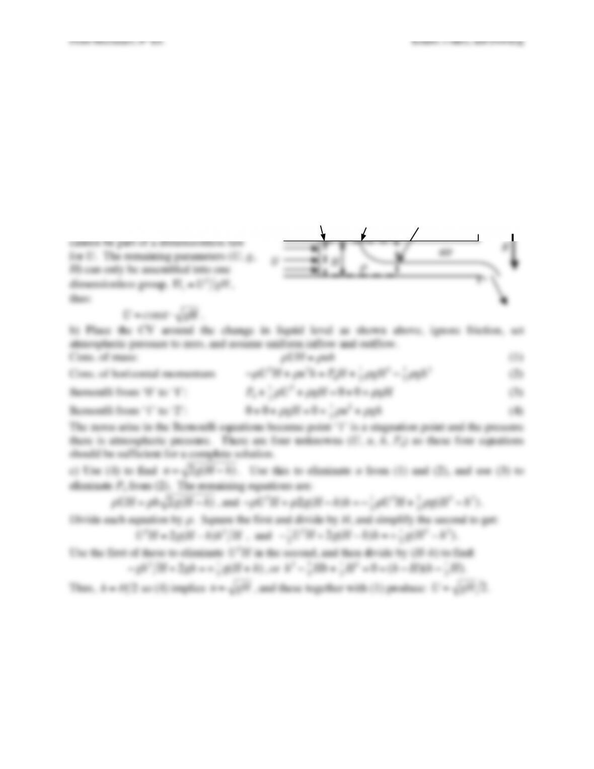
Exercise 4.24. An inviscid incompressible liquid with density
ρ
flows in a wide conduit of
height H and width B into the page. The inlet stream travels at a uniform speed U and fills the
conduit. The depth of the outlet stream is less than H. Air with negligible density fills the gap
above the outlet stream. Gravity acts downward with acceleration g. Assume the flow is steady
for the following items.
a) Find a dimensionless scaling law for U in terms of
ρ
, H, and g.
b) Denote the outlet stream depth and speed by h and u, respectively, and write down a set of
equations that will allow U, u, and h to be determined in terms of
ρ
, H, and g.
c) Solve for U, u, and h in terms of
ρ
, H, and g. [Hint: solve for h first.]
Solution 4.24. a) Density is the only
parameter with units of mass. Thus, it
cannot be part of a dimensionless law
!”
“#$!
$”
%!
&!
‘!
Fluid Mechanics, 6th Ed. Kundu, Cohen, and Dowling
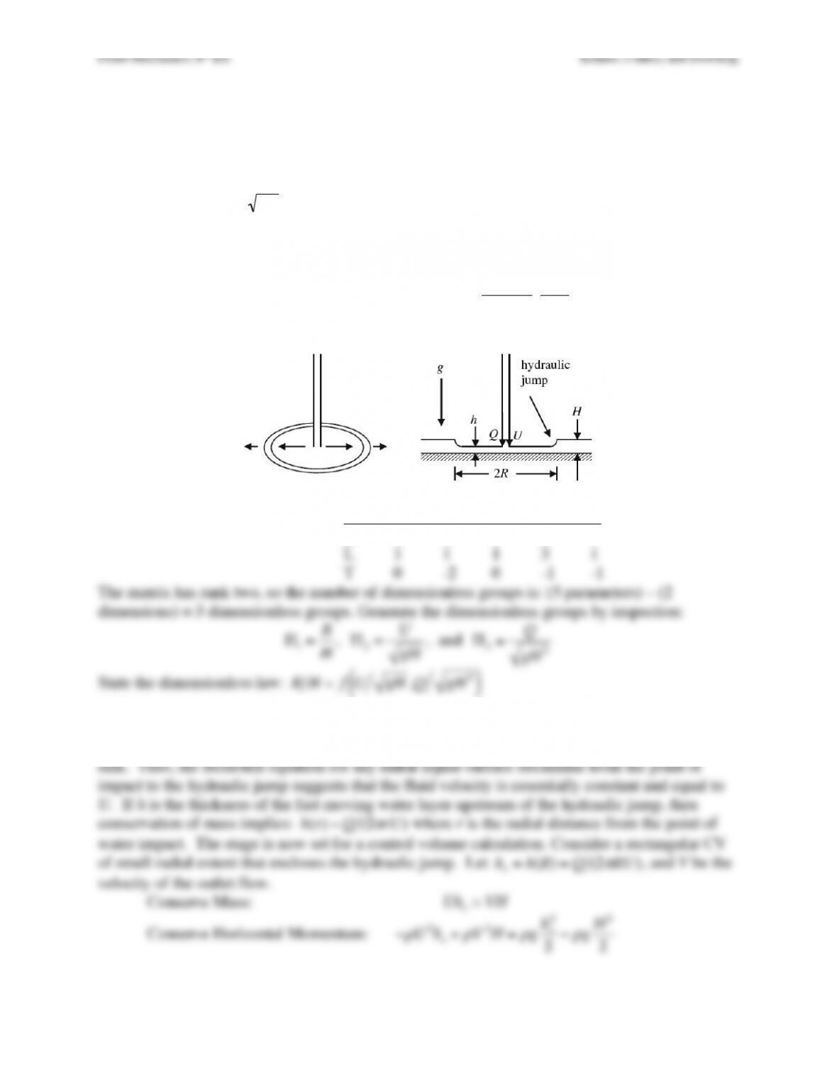
Exercise 4.25. A hydraulic jump is the shallow-water-wave equivalent of a gas-dynamic shock
wave. A steady radial hydraulic jump can be observed safely in one’s kitchen, bathroom, or
backyard where a falling stream of water impacts a shallow pool of water on a flat surface. The
radial location R of the jump will depend on gravity g, the depth of the water behind the jump H,
the volume flow rate of the falling stream Q, and stream’s speed, U, where it impacts the plate.
In your work, assume
2gh << U
where r is the radial coordinate from the point where the falling
stream impacts the surface.
a) Formulate a dimensionless law for R in terms of the other parameters.
b) Use the Bernoulli equation and a control volume with narrow angular and negligible radial
extents that contains the hydraulic jump to show that:
R≅Q
2
π
UH 2
2U2
g−H
%
&
‘
(
)
*
.
c) Rewrite the results of part b) in terms of the dimensionless parameters found for part a).
Solution 4.25. a) Units matrix R g H Q U
M 0 0 0 0 0
L 1 1 1 3 1
b) The pressure is atmospheric on all the water surfaces and observation of kitchen- or bathroom-
sink hydraulic jump suggests that any change of the thickness of the fast moving layer upstream
of the jump is negligible compared to this distance the water has fallen to reach the bottom of the
sink. Thus, the Bernoulli equation for any radial liquid-surface streamline from the point of
Fluid Mechanics, 6th Ed. Kundu, Cohen, and Dowling
Here the conservation of momentum equation specifies a balance between momentum fluxes and
hydrostatic pressure terms. First eliminate V from the second equation using the first.
−
ρ
U2ho+
ρ
Uho
H
$
%
& ‘
(
)
2
H=
ρ
gho
2
2−
ρ
gH2
2
Divide by
ρ
, and manipulate this equation to eliminate a common factor of H – ho.
−U2ho
H(H−ho)=−g
2H−ho
( )
H+ho
( )
–>
U2ho
H=g
2H+ho
( )
–>
ho2U2
gH −1
#
$
%
&
‘
( =H
Now use the relationship
ho=h(R)=Q(2
π
RU)
to eliminate ho and solve for R:
Q
2
π
RU
2U2
gH −1
$
%
&
‘
(
) =H
–>
R=Q
2
π
UH 22U2
g−H
$
%
&
‘
(
)
c) Putting this result into dimensionless form just takes a little algebra. The final result is:
R
H=1
2
π
Q
gH 5
2U
gH −gH
U
$
%
&
‘
(
)
Fluid Mechanics, 6th Ed. Kundu, Cohen, and Dowling
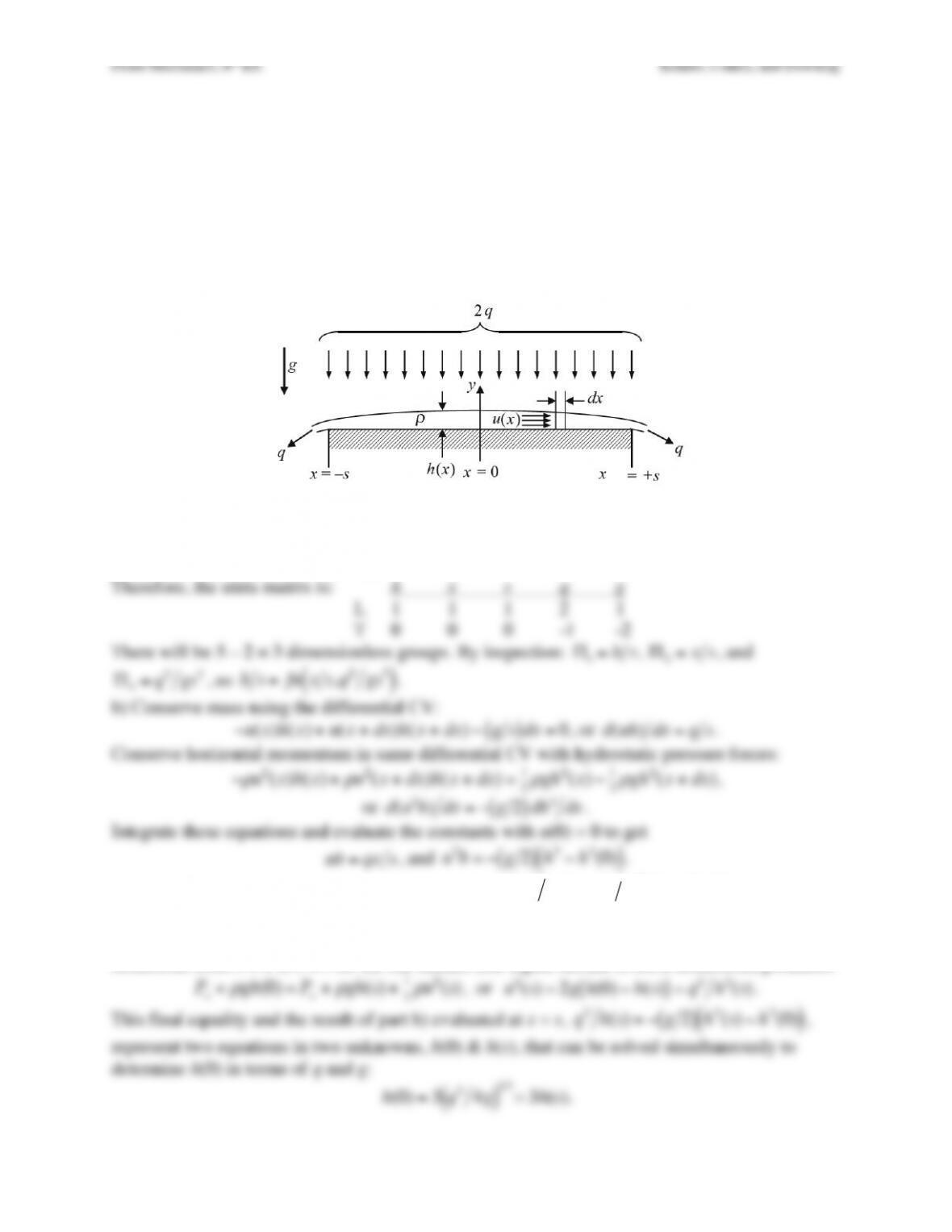
Exercise 4.26. A fine uniform mist of an inviscid incompressible fluid with density
ρ
settles
steadily at a total volume flow rate (per unit depth into the page) of 2q onto a flat horizontal
surface of width 2s to form a liquid layer of thickness h(x) as shown. The geometry is two-
dimensional.
a) Formulate a dimensionless scaling law for h in terms of x, s, q,
ρ
, and g.
b) Use a suitable control volume analysis, assuming u(x) does not depend on y, to find a single
cubic equation for h(x) in terms of h(0), s, q, x, and g.
c) Determine h(0).
Solution 4.26. a) There appear to be six parameters, but the density is the only parameter that
includes the units of mass so it can be set aside. Thus, there will only be two independent
dimensions, length (L) and time (T).
Therefore, the units matrix is: h x s q g
Eliminate u(x) between these two equations to find:
q2x2hs2=−g2
( )
h2−h2(0)
( )
, which is a
cubic equation so h(x) cannot be put into a simple form.
c) Global conservation of mass implies:
q=u(s)h(s)
. If Pa = atmospheric pressure, a Bernoulli
streamline from x = 0 to x = s on the flat surface (the liquid surface is not a streamline) produces:
Pa+
ρ
gh(0) =Pa+
ρ
gh(s)+1
2
ρ
u2(s)
, or
u2(s)=2g h(0) −h(s)
( )
=q2h2(s)
.
This final equality and the result of part b) evaluated at x = s,
q2h(s)=−g2
( )
h2(s)−h2(0)
( )
,
represent two equations in two unknowns, h(0) & h(s), that can be solved simultaneously to
determine h(0) in terms of q and g:
h(0) =3q24g
( )
1 3
= 3h(s).
Fluid Mechanics, 6th Ed. Kundu, Cohen, and Dowling
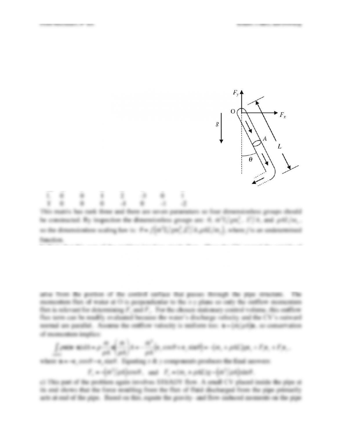
Exercise 4.27. A thin-walled pipe of mass mo, length L, and cross sectional area A is free to
swing in the x–y plane from a frictionless pivot at point O. Water with density
ρ
fills the pipe,
flows into it at O perpendicular to the x–y plane, and is expelled at a right angle from the pipe’s
end as shown. The pipe’s opening also has area A and gravity g acts downward. For a steady
mass flow rate of
˙
m
, the pipe hangs at angle
θ
with respect to the vertical as shown. Ignore fluid
viscosity.
a) Develop a dimensionless scaling law for
θ
in terms of mo,
L, A,
ρ
,
˙
m
, and g.
b) Use a control volume analysis to determine the force
components, Fx & Fy, applied to the pipe at the pivot point in
terms of
θ
, mo, L, A,
ρ
,
˙
m
, and g.
c) Determine
θ
in terms of mo, L, A,
ρ
,
˙
m
, and g.
d) Above what value of
˙
m
will the pipe rotate without
stopping?
Solution 4.27. a) The units matrix is:
θ
mo L A
ρ
˙
m
g
–––––––––––––––––––––––––––––––––––––
M 0 1 0 0 1 1 0
L 0 0 1 2 -3 0 1
the pipe except at the pivot point O where the CV slices through the pipe parallel to the x–y
plane. Assume that the flow is in the z-direction across this control surface slice at O. Here,
conservation of mass merely requires
˙
m
= const. The control surface pressure is atmospheric
everywhere outside the pipe, and pressure forces can only act in the z-direction on the control
surface slice at O. Thus, there is no pressure contribution to the reaction forces, Fx and Fy, which
arise from the portion of the control surface that passes through the pipe structure. The
Fluid Mechanics, 6th Ed. Kundu, Cohen, and Dowling
Fluid Mechanics, 6th Ed. Kundu, Cohen, and Dowling
Exercise 4.28. Construct a house of cards, or light a candle. Get the cardboard tube from the
center of a roll of paper towels and back away from the cards or candle several feet so that by
blowing you cannot knock down the cards or blow out the candle unaided. Now use the tube in
two slightly different configurations. First, place the tube snugly against your face encircling
your mouth, and try to blow down the house of cards or blow out the candle. Repeat the
experiment while moving closer until the cards are knocked down or the candle is blown out
(you may need to get closer to your target than might be expected; do not hyperventilate; do not
start the cardboard tube on fire). Note the distance between the end of the tube and the card
house or candle at this point. Rebuild the card house or relight the candle and repeat the
experiment, except this time hold the tube a few centimeters away from your face and mouth,
and blow through it. Again, determine the greatest distance from which you can knock down the
cards or blow out the candle.
a) Which configuration is more effective at knocking the cards down or blowing the candle out?
b) Explain your findings with a suitable control-volume analysis.
c) List some practical applications where this effect might be useful.
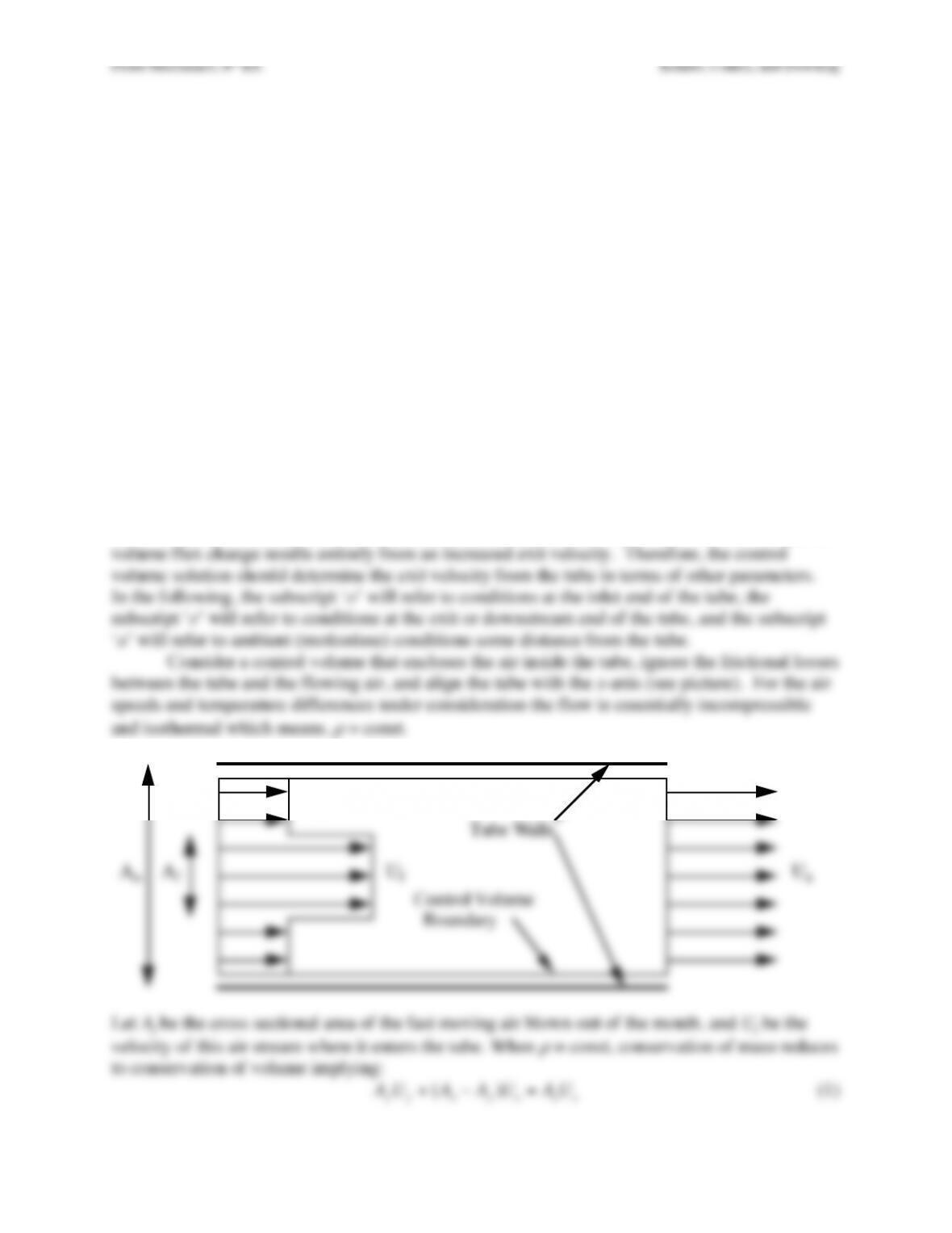
Solution 4.28. a) The most effective configuration is when the tube is held a few centimeters in
front of the face and mouth.
b) The difference between the two cases is the greater volume flux through the tube when it is
held a few centimeters in front of the mouth. Since the exit area of the tube does not change, the
volume flux change results entirely from an increased exit velocity. Therefore, the control
Tube Walls
Control Volume
Boundary
Ue
Uf
Uo
Af
Ao
po
pe
Fluid Mechanics, 6th Ed. Kundu, Cohen, and Dowling
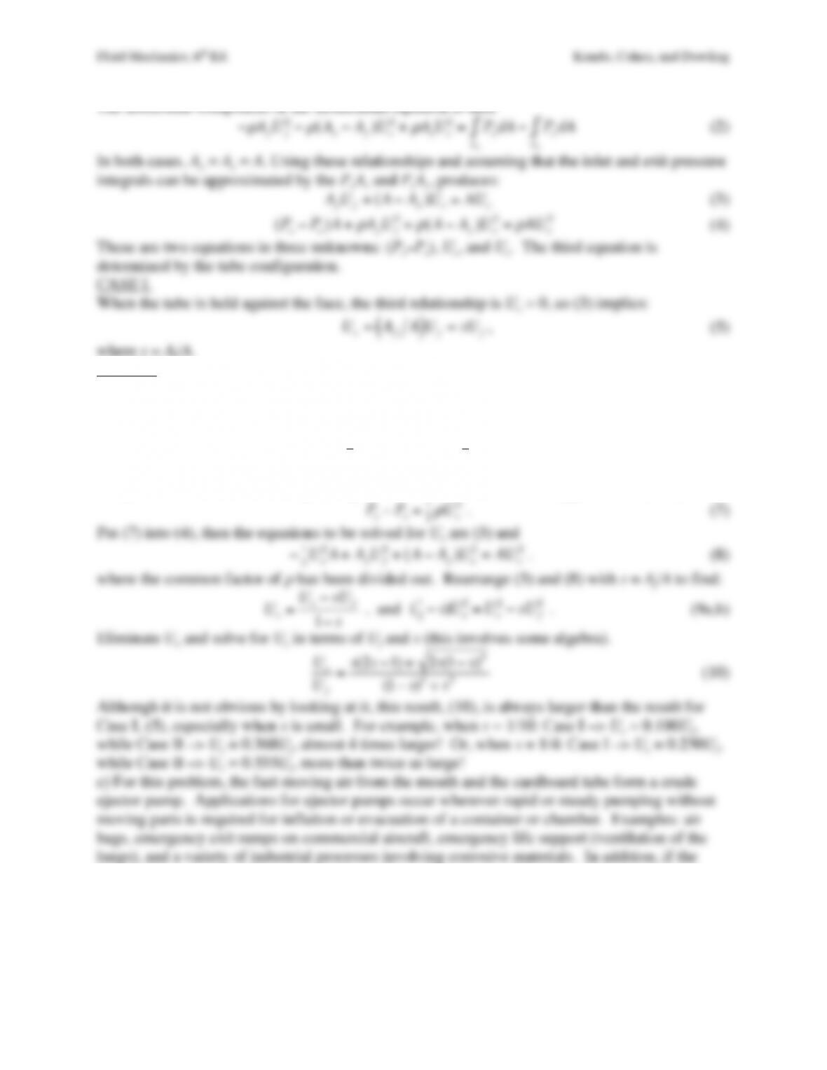
The horizontal-component of the momentum equation is then
−
ρ
AfUf
2−
ρ
(Ao−Af)Uo
2+
ρ
AeUe
2=PodA
Ao
∫−PedA
Ae
∫
(2)
In both cases, Ao = Ae = A. Using these relationships and assuming that the inlet and exit pressure
integrals can be approximated by the PoAo and PeAe, produces:
AfUf+(A−Af)Uo=AUe
(3)
(Po−Pe)A+
ρ
AfUf
2+
ρ
(A−Af)Uo
2=
ρ
AUe
2
(4)
These are two equations in three unknowns: (Po–Pe), Uo, and Ue. The third equation is
determined by the tube configuration.
CASE I.
When the tube is held against the face, the third relationship is Uo = 0, so (3) implies:
Ue=AfA
( )
Uf=sU f
, (5)
where s = Af/A.
CASE II.
When the tube is held away from the mouth. The remaining relationship comes from a pressure
balance outside the tube. The pressure of the air drawn into the tube from the ambient condition
can be estimated from the steady Bernoulli equation:
P
a+1
2
ρ
Ua
2=P
a=P
o+1
2
ρ
Uo
2
(6)
where, of course, Ua ≈ 0. In addition, if the exit velocity is parallel to the tube axis, then the
component of the momentum equation perpendicular to the tube axis suggests that Pa ≈ Pe so that
P
e−P
o=1
2
ρ
Uo
2
. (7)
Put (7) into (4), then the equations to be solved for Ue are (3) and
−1
2Uo
2A+AfUf
2+(A−Af)Uo
2=AUe
2
. (8)
where the common factor of
ρ
has been divided out. Rearrange (3) and (8) with s = Af/A to find:
Uo=Ue−sU f
1−s
, and
(1
2−s)Uo
2=Ue
2−sU f
2
. (9a,b)
Eliminate Uo and solve for Ue in terms of Uf and s (this involves some algebra).
Ue
Uf
=s(2s−1) +2s(1−s)3
(1−s)2+s2
(10)
Although it is not obvious by looking at it, this result, (10), is always larger than the result for
Case I, (5), especially when s is small. For example, when s = 1/10: Case I –> Ue = 0.100Uf,
while Case II –> Ue = 0.368Uf, almost 4 times larger! Or, when s = 1/4: Case I –> Ue = 0.250Uf,
while Case II –> Ue = 0.535Uf, more than twice as large!
c) For this problem, the fast-moving air from the mouth and the cardboard tube form a crude
ejector pump. Applications for ejector pumps occur wherever rapid or steady pumping without
moving parts is required for inflation or evacuation of a container or chamber. Examples: air
bags, emergency exit ramps on commercial aircraft, emergency life support (ventilation of the
lungs), and a variety of industrial processes involving corrosive materials. In addition, if the
fast-moving stream carries a fuel and the entrained fluid carries the oxidizer (for example), the
shape (i.e. the area ratio) of the ejector pump can be used to mix reactants to a set the mixture
ratio for combustion.