Fluid Mechanics, 6th Ed. Kundu, Cohen, and Dowling
Exercise 14.1. As an extension of Example 14.1, consider a sphere with radius a that moves
along the x-axis on a trajectory given by xp(t) = xp(t)ex in a fluid moving with uniform velocity: u
= Uex + Vey. Determine a formula for the mechanical power, W, necessary to overcome the
aerodynamic drag force on the sphere in terms of a, U, V, xp,
ρ
= the density of the air, and CD =
the drag coefficient of the sphere. If dxp/dt is constant, under what conditions is W reduced by the
presence of non-zero u?
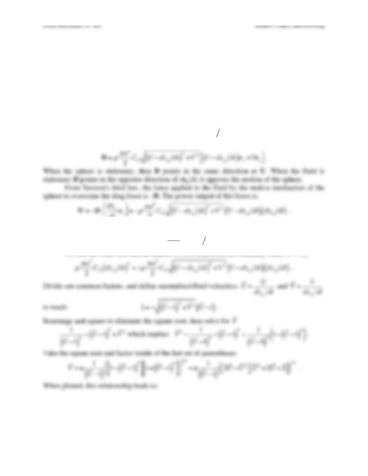
Solution 14.1. The drag force magnitude will depend on the square of the relative velocity
between the sphere and the fluid. The drag force direction will be parallel to the relative velocity
of the sphere and the fluid. The relative velocity is the fluid velocity observed when riding on the
sphere. If the fluid velocity is u = (U,V), then
Vrel =U−dxpdt
( )
ex+Vex
, so the drag force vector
is:
D=
ρπ
a2
2CDU−dxpdt
( )
2+V2U−dxpdt
( )
ex+Vex
“
#$
%
.
When the sphere is stationary, then D points in the same direction as U. When the fluid is
stationary D points in the opposite direction of dxp/dt; it opposes the motion of the sphere.
From Newton’s third law, the force applied to the fluid by the motive mechanism of the
sphere to overcome the drag force is –D. The power output of this force is:
W=−D⋅dxp
dt
ex
#
$
%&
‘
(=−
ρπ
a2
2CDU−dxpdt
( )
2+V2U−dxpdt
( )
dxpdt
( )
.
When the fluid velocity is zero, then the power is:
Wo=
ρπ
a2
2CDdxpdt
( )
3
.
To find out when non-zero u reduces W, first determine the boundary where W = Wo
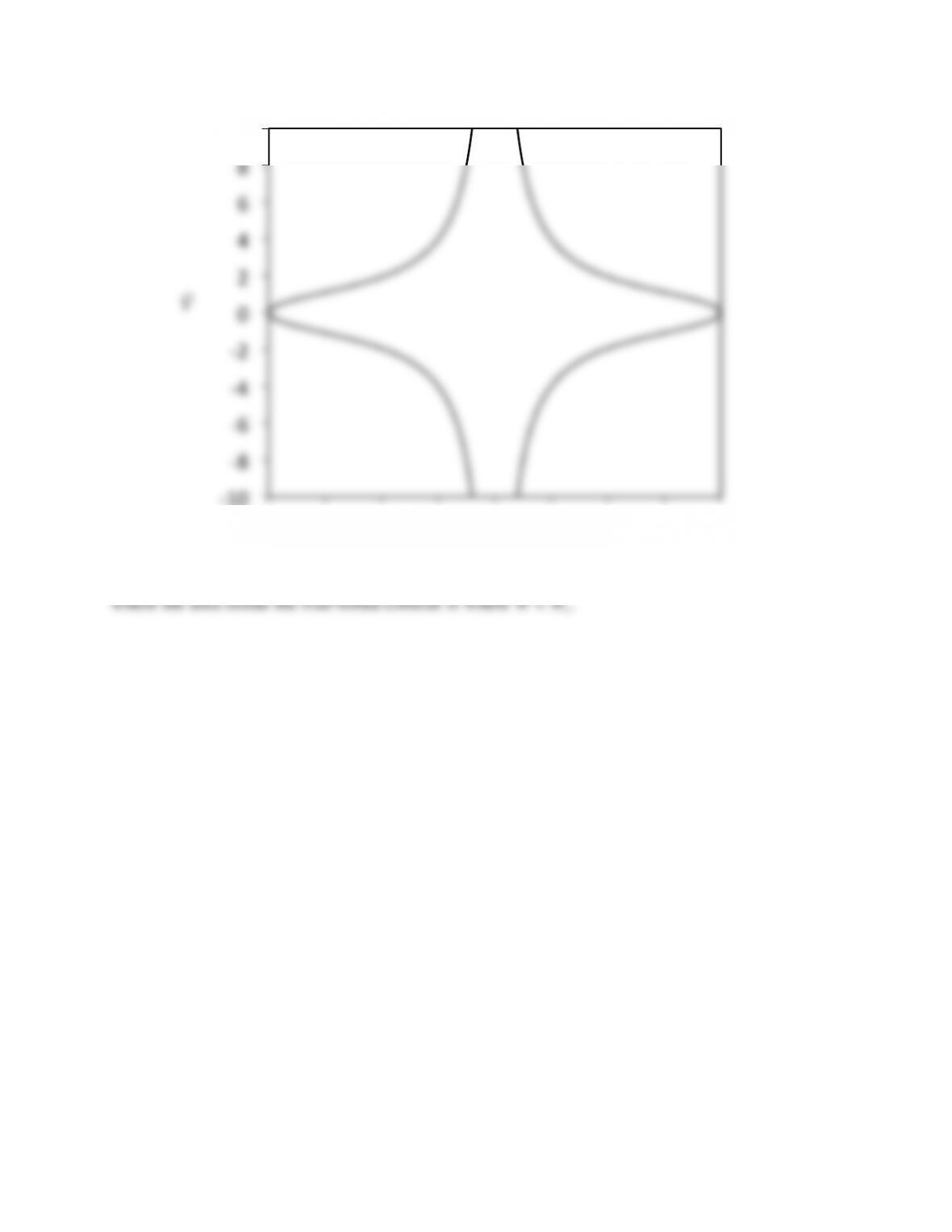
Fluid Mechanics, 6th Ed. Kundu, Cohen, and Dowling
where the area inside the four-lobed contour is where W < Wo.
!10$
!8$
!6$
!4$
!2$
0$
2$
4$
6$
8$
10$
0$ 0.25$ 0.5$ 0.75$ 1$ 1.25$ 1.5$ 1.75$ 2$
!
V
!
U
Fluid Mechanics, 6th Ed. Kundu, Cohen, and Dowling
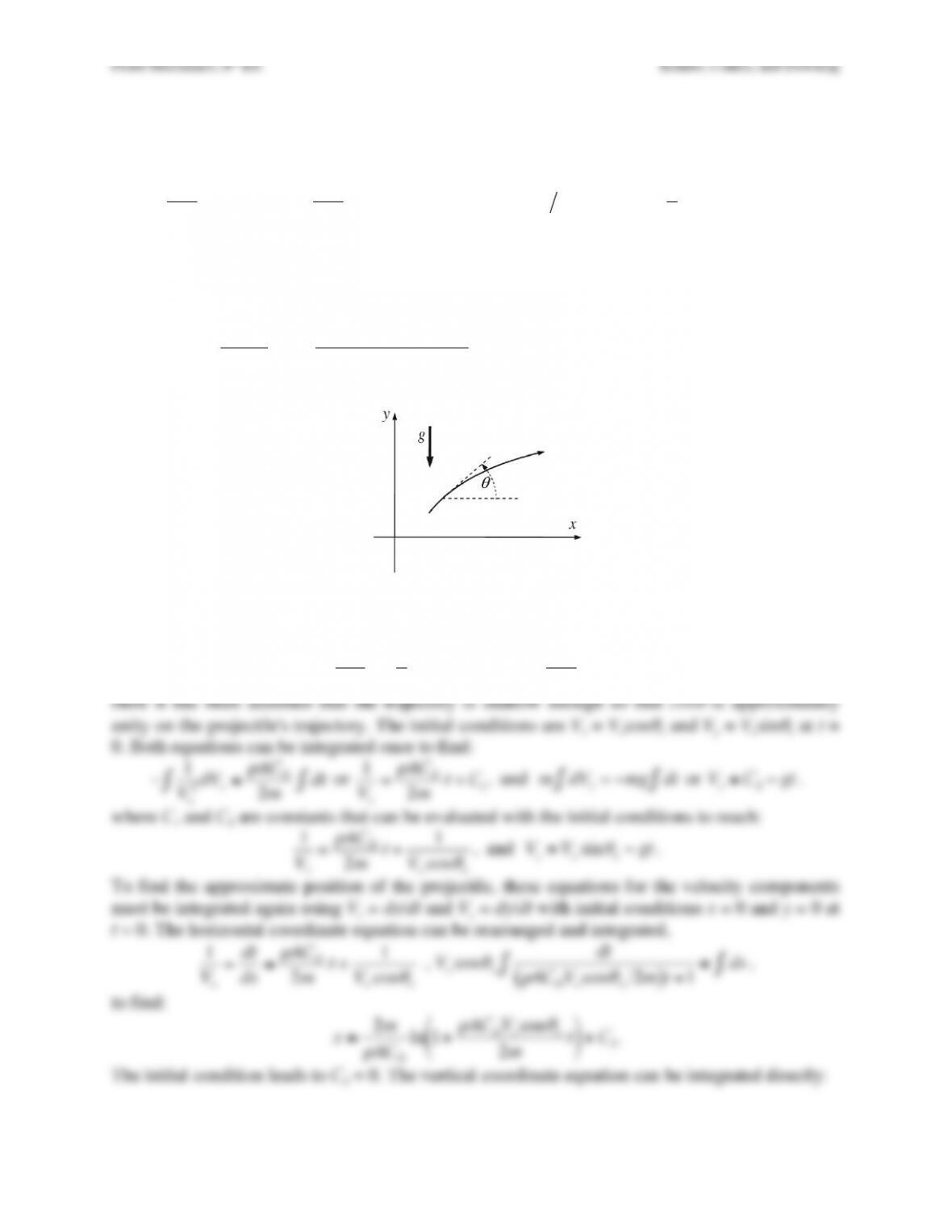
Exercise 14.2. Consider the elementary aerodynamics of a projectile of mass m with CL = 0 and
CD = constant. In Cartesian coordinates with gravity g acting downward along the y-axis, a set of
equations for such a projectile’s motion are:
mdVx
dt =−Dcos
θ
,
mdVy
dt =−mg −Dsin
θ
,
tan
θ
=VyVx
, and
D=1
2
ρ
Vx
2+Vy
2
( )
ACD
,
where Vx and Vy are the horizontal and vertical components of the projectile’s velocity,
θ
is the
angle of the projectile’s trajectory with respect to the horizontal, D is the drag force on the
projectile,
ρ
is the air density, and A is projectile’s frontal area. Assuming a shallow trajectory,
where
Vx
2>> Vy
2
and
mg >> Dsin
θ
, show that the distance traveled by the projectile over level
ground is:
x≅2m
ρ
ACD
ln 1+
ρ
ACDVo
2cos
θ
osin
θ
o
mg
%
&
‘
(
)
*
if it is launched from ground level with speed
of Vo at an angle of
θ
o with respect to the horizontal. Does this answer make sense as
CD→0
?
Solution 14.2. Insert the approximations in the horizontal and vertical equations of motion to
find:
mdVx
dt ≅ − 1
2
ρ
Vx
2ACD
, and
mdVy
dt ≅ −mg
.
Here it has been assumed that the trajectory is shallow enough so that cos
θ
is approximately
Fluid Mechanics, 6th Ed. Kundu, Cohen, and Dowling
Vy=dy
dt ≅Vosin
θ
o−gt
or
y≅Votsin
θ
o−1
2gt2+C4
.
and the initial condition again leads to C4 = 0.
The time, tf, the projectile is in flight over level ground can be determined from the
vertical coordinate equation by looking for the second time y = 0:
y=0≅Votfsin
θ
o−1
2gt f
2
, which implies: tf = 0 , or
tf≅2Vosin
θ
o
g
.
Substituting this time into the horizontal coordinate equation determines the projectile’s
horizontal location when it hits the ground:
x≅2m
ρ
ACD
ln 1+
ρ
ACDVo
2cos
θ
osin
θ
o
mg
%
&
‘
(
)
*
.
When
CD→0
the frictionless mechanics solution should be recovered. Using the
expansion of the natural logarithm, ln(1 +
ε
) =
ε
+ … for
ε
<< 1, the above equation becomes:
x≅2m
ρ
ACD
ρ
ACDVo
2cos
θ
osin
θ
o
mg =2Vo
2cos
θ
osin
θ
o
g
,
which is correct when the projectile flies in vacuum.
Although the main result of this exercise is approximate, it does incorporate the
physically important feature that aerodynamic drag decreases projectile travel distances in still
air.
Fluid Mechanics, 6th Ed. Kundu, Cohen, and Dowling
Exercise 14.3. As a model of a two-dimensional airfoil’s trailing edge flow consider the potential
φ
(r,
θ
)=Ud n
( )
r d
( )
ncos n
θ
( )
in the usual r–
θ
coordinates (Figure 3.3a). Here U, d, and n are
positive constants, the fluid has density
ρ
, and the foil’s trailing edge lies at the origin of
coordinates.
a) Sketch the flow for n = 3/2, 5/4, and 9/8 in the angle range |
θ
| < π/n, and determine the full
included angle of the foil’s trailing edge in terms of n.
b) Determine the fluid velocity at r = d and
θ
= 0.
c) If p0 is the pressure at the origin of coordinates and pd is the pressure at r = d and
θ
= 0,
determine the pressure coefficient:
Cp=(p0−pd)1
2
ρ
U2
( )
as a function of n. In particular, what
is Cp when n = 1 and when n > 1?
Solution 14.3. a) The velocity components in this flow are:
ur=
∂
∂
r
φ
=Ud
n
nrn−1
dncos(n
θ
)=Ur
d
&
‘
( )
*
+
n−1
cos(n
θ
)
, and
u
θ
=1
r
∂
∂θφ
=Ud
n
rn−1
dn−n
( )
sin(n
θ
)=−Ur
d
&
‘
( )
*
+
n−1
sin(n
θ
)
.
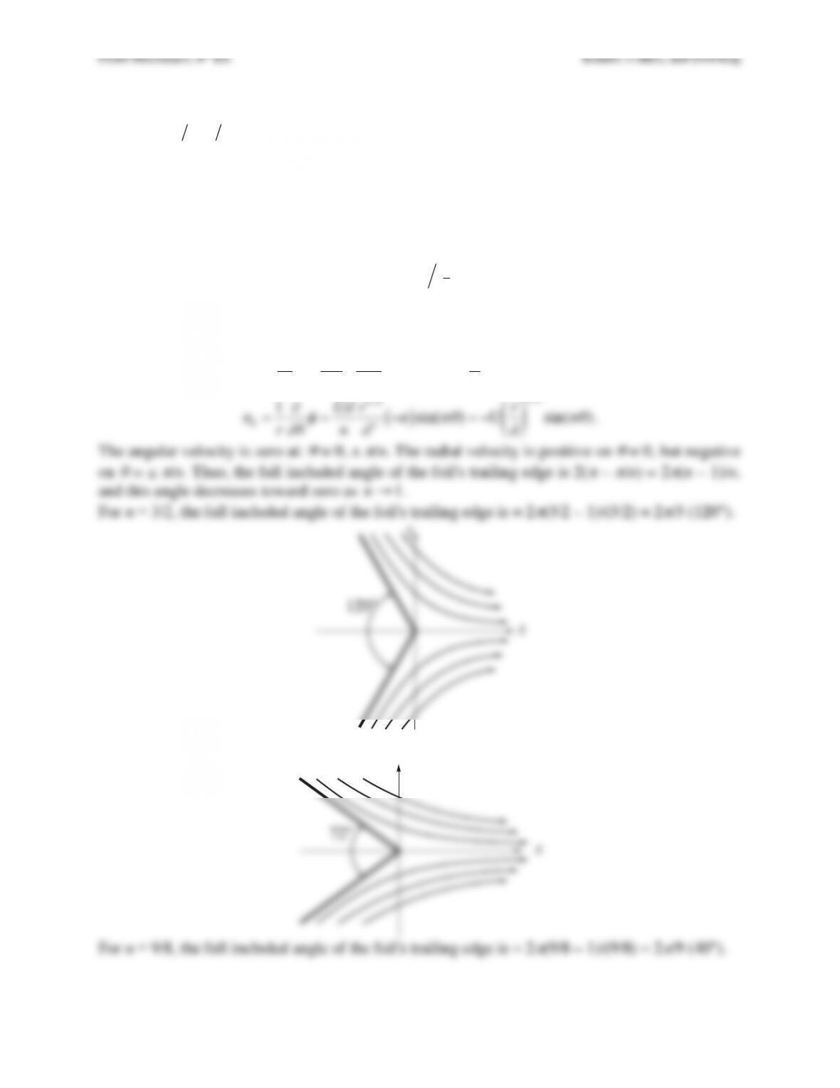
The angular velocity is zero at:
θ
= 0, ±
π
/n. The radial velocity is positive on
θ
= 0, but negative
on
θ
= ±
π
/n. Thus, the full included angle of the foil’s trailing edge is 2(
π
–
π
/n) = 2
π
(n – 1)/n,
and this angle decreases toward zero as
n→1
.
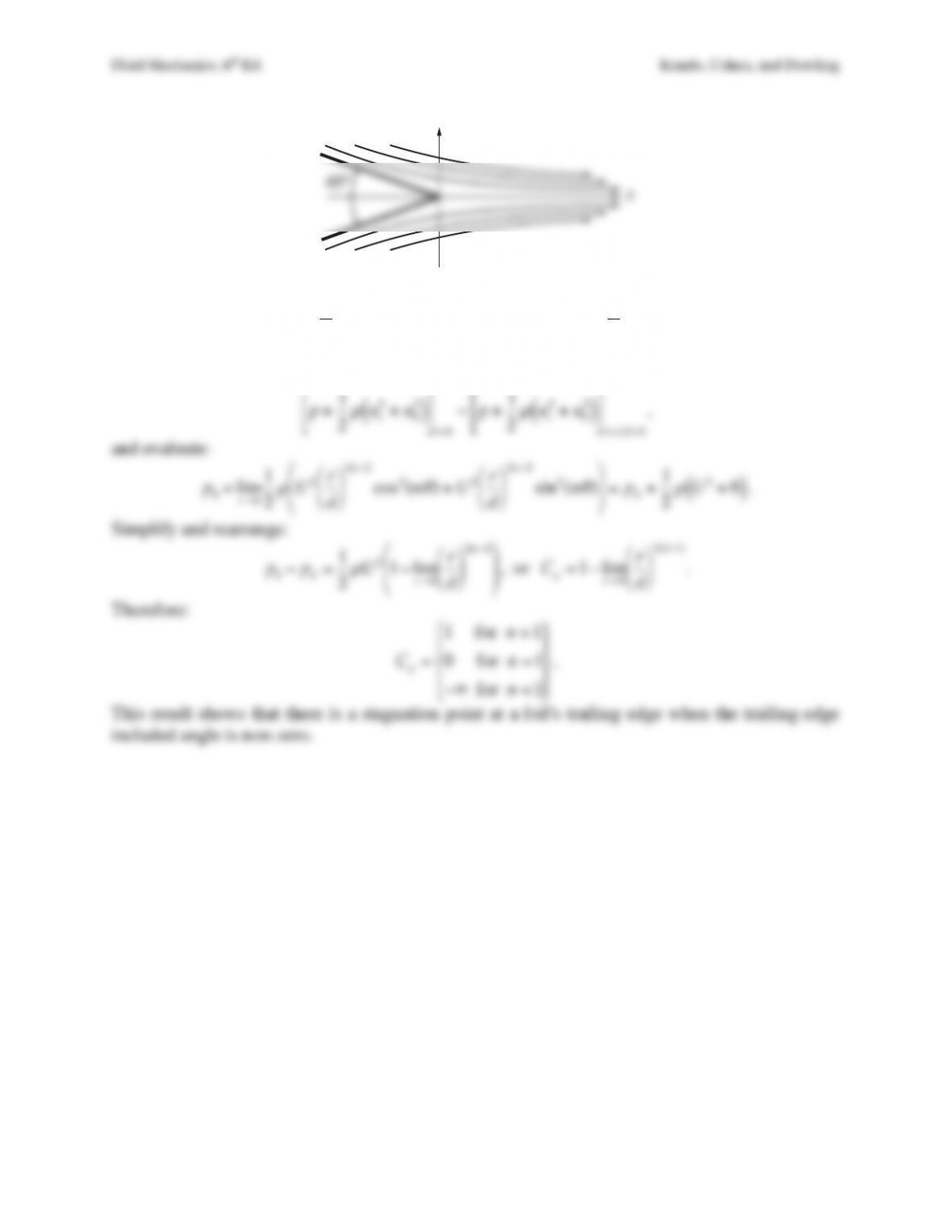
For n = 3/2, the full included angle of the foil’s trailing edge is = 2
π
(3/2 – 1)/(3/2) = 2
π
/3 (120°).
For n = 5/4, the full included angle of the foil’s trailing edge is = 2
π
(5/4 – 1)/(5/4) = 2
π
/5 (72°).
x
y
120°
x
y
72°
Fluid Mechanics, 6th Ed. Kundu, Cohen, and Dowling
b) From the velocity results provided above in part a), the fluid velocity at r = d and
θ
= 0 is:
ur(d,0) =Ud
d
“
#
$ %
&
‘
n−1
cos(0) = +U
, and
u
θ
(d,0) =−Ud
d
$
%
& ‘
(
)
n−1
sin(0) =0
.
c) To determine the coefficient of pressure, use the steady-flow Bernoulli equation without the
body-force term:
p+1
2
ρ
ur
2+u
θ
2
( )
$
%
&
‘
(
)
r=0
=p+1
2
ρ
ur
2+u
θ
2
( )
$
%
&
‘
(
)
r=d,
θ
=0
,
and evaluate:
p0+lim
r→0
1
2
ρ
U2r
d
$
%
& ‘
(
)
2n−2
cos2(n
θ
)+U2r
d
$
%
& ‘
(
)
2n−2
sin2(n
θ
)
$
%
&
&
‘
(
)
) =pd+1
2
ρ
U2+0
( )
.
Simplify and rearrange:
p0−pd=1
2
ρ
U21−lim
r→0
r
d
%
&
‘ (
)
*
2n−2
%
&
‘
‘
(
)
*
*
, or
Cp=1−lim
r→0
r
d
$
%
& ‘
(
)
2(n−1)
.
Therefore:
Cp=
1 for n>1
0 for n=1
−∞ for n<1
$
%
&
‘
&
(
)
&
*
&
.
This result shows that there is a stagnation point at a foil’s trailing edge when the trailing-edge
included angle is non-zero.
x
y
40°
Fluid Mechanics, 6th Ed. Kundu, Cohen, and Dowling
Exercise 14.4. Consider an airfoil section in the xy-plane, the x-axis being aligned with the chord
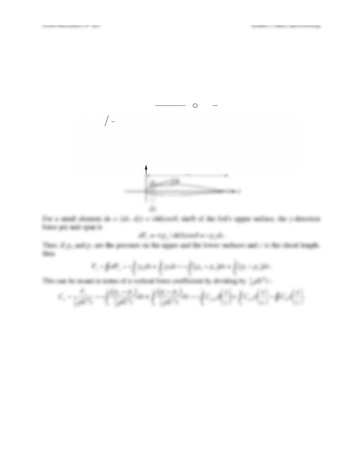
line. Examine the pressure forces on an element ds = (dx, dy) on the surface, and show that the
net force (per unit span) in the y-direction is
Fy=−pudx
0
c
∫+pldx
0
c
∫
where pu and p1 are the pressure on the upper and the lower surfaces and c is the chord length.
Show that this relation can be rearranged in the form
Cy=Fy
(1/2)
ρ
U2c=Cpdx
c
#
$
% &
‘
(
∫
,
where
Cp=(p0−p∞)1
2
ρ
U2
( )
, and the integral represents the area enclosed in a Cp vs x/c
diagram, such as Figure 14.8. Neglect shear stresses. [Note that Cy is not exactly the lift
coefficient, since the airstream is inclined at a small angle
α
with respect to the x-axis.]
Solution 14.4. Here’s a nominal drawing of a foil with the x-axis along the chord line of length c.
dx
y
!
ds
x
c
Fluid Mechanics, 6th Ed. Kundu, Cohen, and Dowling
Exercise 14.5. The measured pressure distribution over a section of a two-dimensional airfoil at
4° incidence has the following form:
Upper Surface: Cp is constant at −0.8 from the leading edge to a distance equal to
60% of chord and then increases linearly to 0.1 at the trailing edge.
Lower Surface: Cp is constant at −0.4 from the leading edge to a distance equal to
60% of chord and then increases linearly to 0.1 at the trailing edge.
Using the results of Exercise 14.4, show that the lift coefficient is nearly 0.32.
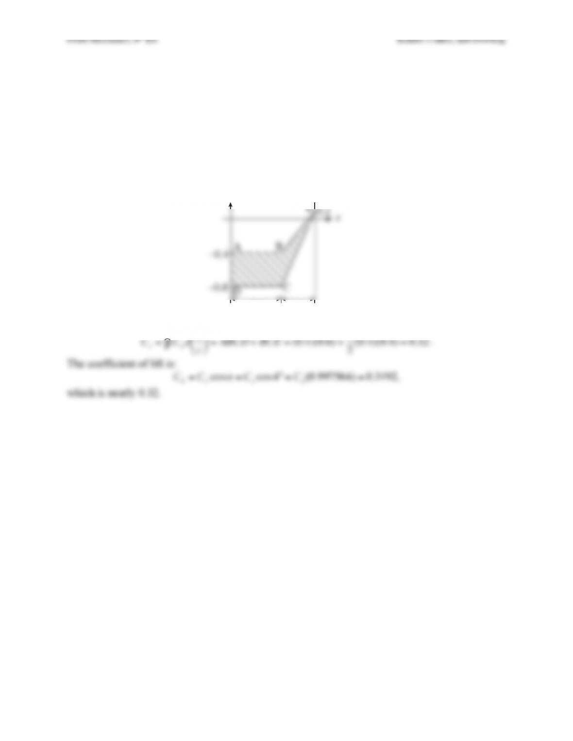
Solution 14.5.The distribution of the pressure coefficient is sketched below.
Using the result of Exercise 14.3,
Cy=Cp
∫dx
c
#
$
% &
‘
( =ABCD +BCE =(0.4)(0.6) +1
2(0.4)(0.4) =0.32
.
The coefficient of lift is:
CL=Cycos
α
=Cycos 4° = Cy(0.997564) =0.3192
,
which is nearly 0.32.
–!”#
–!”$
!”%
0.4c
0.6c
x
Cp
AB
E
C
D
Fluid Mechanics, 6th Ed. Kundu, Cohen, and Dowling
Exercise 14.6. Zhukhovsky transformation z =
ζ
+ b2/
ζ
transforms a circle of radius b, centered
at the origin of the
ζ
-plane, into a flat plate of length 4b in the z-plane. The circulation around the
cylinder is such that the Kutta condition is satisfied at the trailing edge of the flat plate. If the
plate is inclined at an angle
α
to a uniform stream U, show that
(i) The complex potential in the
ζ
-plane is
w=U
ζ
e−i
α
+b2
ζ
e+i
α
“
#
$%
&
‘+iΓ
2
π
ln
ζ
e−i
α
( )
, where Γ =
4
π
Ubsin
α
. Note that this represents flow over a circular cylinder with circulation, in
which the oncoming velocity is oriented at an angle
α
.
(ii) The velocity components at point P (−2b, 0) in the
ζ
-plane are
3
4Ucos
α
,9
4Usin
α
!
“#
$
(iii) The coordinates of the transformed point P# in the xy-plane are [−5b/2, 0].
(iv) The velocity components at [−5b/2, 0] in the xy-plane are [Ucos
α
, 3Usin
α
].
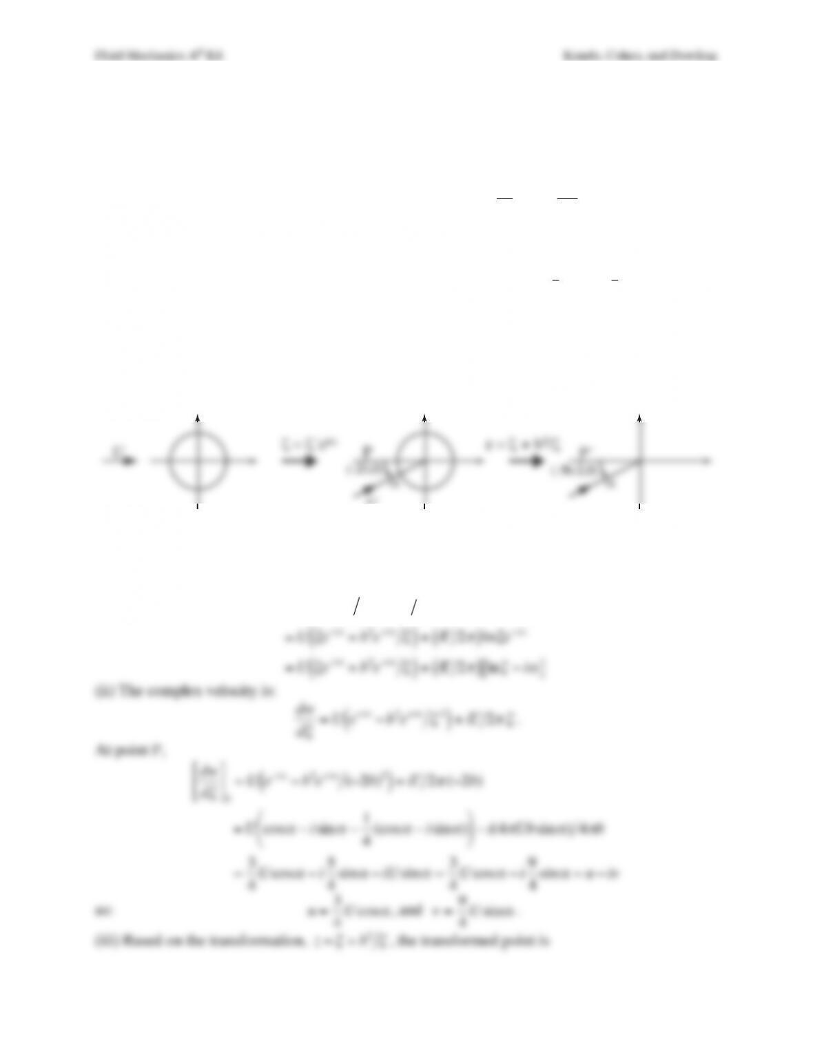
Solution 14.6. The three complex planes for this problem appear as:
(i) From equation (14.11), the circulation will be
Γ=4
π
Ubsin
α
. In the
ζ
´-plane choose U to
flow parallel to the real axis. Then, the transformation
ζ
=#
ζ
ei
α
rotates the
ζ
´-plane counter-
clockwise to produce the
ζ
-plane. The complex potential is:
w=U“
ζ
+b2“
ζ
( )
+iΓ2
π
( )
ln “
ζ
=U
ζ
e−i
α
+b2e+i
αζ
( )
+iΓ2
π
( )
ln
ζ
e−i
α
=U
ζ
e−i
α
+b2e+i
αζ
( )
+iΓ2
π
( )
ln
ζ
−i
α
[ ]
(ii) The complex velocity is:
dw
d
ζ
=U e−i
α
−b2e+i
αζ
2
( )
+iΓ2
π ζ
.
At point P,
dw
d
ζ
#
$
%
&
‘
(
P
=U e−i
α
−b2e+i
α
(−2b)2
( )
+iΓ2
π
(−2b)
=Ucos
α
−isin
α
−1
4(cos
α
−isin
α
)
–
.
/ 0
1
2 −i(4
π
Ubsin
α
) 4
π
b
=3
4
Ucos
α
−i5
4sin
α
−iU sin
α
=3
4
Ucos
α
−i9
4sin
α
=u−iv
so:
u=3
4
Ucos
α
, and
v=9
4
Usin
α
.
(iii) Based on the transformation,
z=
ζ
+b2
ζ
, the transformed point is
!
´-plane
! = !´ei“
U
!
-plane
U
“
z-plane
P
(-2b,0)
P´
(-5b/2,0)
z = !#+ b2/!
“
Fluid Mechanics, 6th Ed. Kundu, Cohen, and Dowling
Fluid Mechanics, 6th Ed. Kundu, Cohen, and Dowling
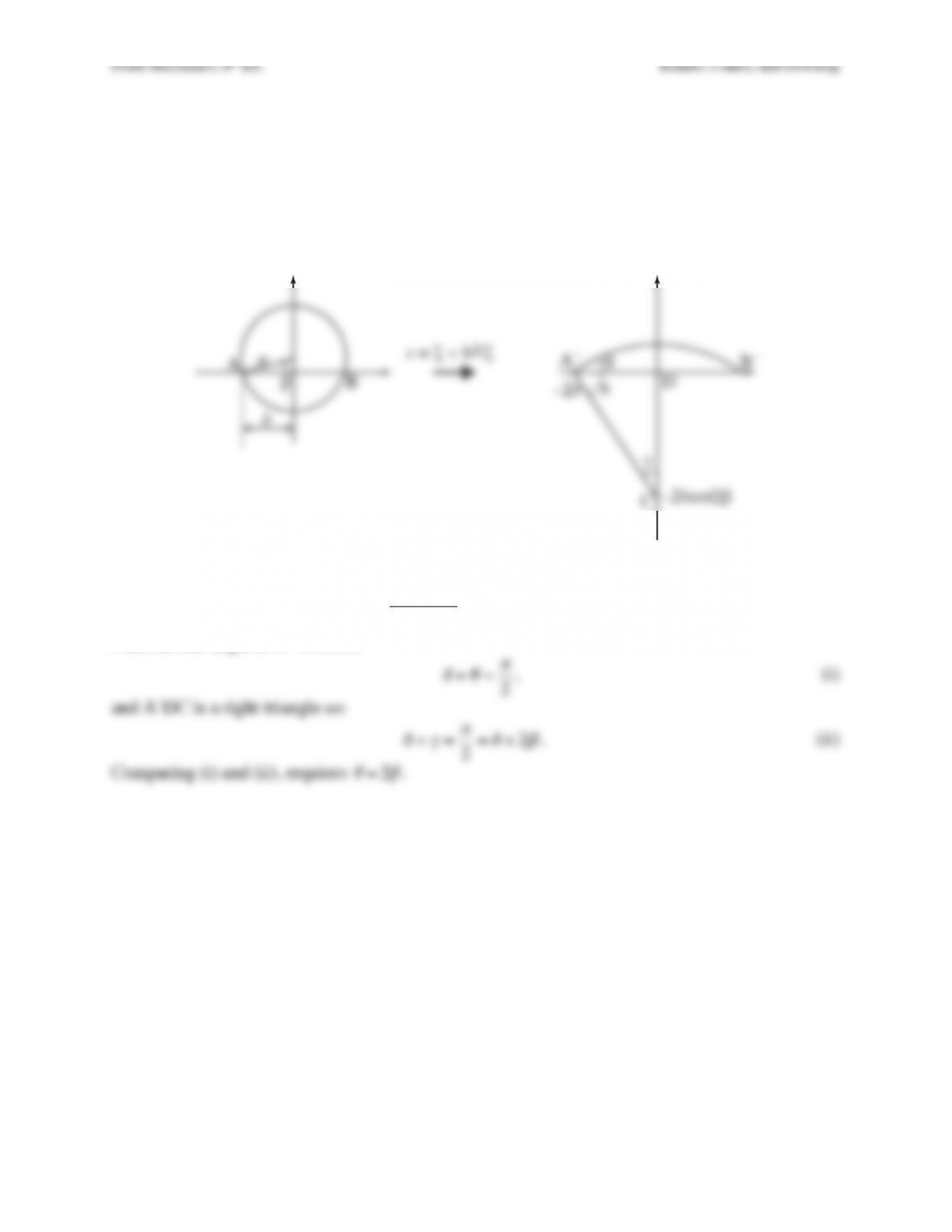
Exercise 14.7. In Figure 14.13, the angle at A# has been marked 2
β
. Prove this. [Hint: Locate the
center of the circular arc in the z-plane.]
Solution 14.7. From the discussion following Figure 14.12, point C is located on the imaginary
axis in the z-plane at –2bcot2
β
.
From triangle A´DC
tan
γ
=2b
2bcot 2
β
=tan2
β
, so
γ
= 2
β
.
Plus, the full angle at A´ is π/2 so
δ
+
θ
=
π
2
, (i)
and A´DC is a right triangle so:
δ
+
γ
=
π
2=
δ
+2
β
. (ii)
Comparing (i) and (ii), requires
θ
=2
β
.
!-plane
D
z-plane
z = !”+ b2/!
A
B#
aA´ B´
$
%
&
b
–2b
C–2bcot2#
Fluid Mechanics, 6th Ed. Kundu, Cohen, and Dowling
Exercise 14.8. Ideal flow past a flat plate inclined at angle
α
with respect to a horizontal free
stream produces lift but no drag when the Kutta condition is applied at the plate’s trailing edge.
However, pressure forces can only act in the plate-normal direction and this direction is not
perpendicular to the flow. Therefore, to achieve zero drag, another force must act on the plate.
This extra force is known as leading-edge suction and its existence can be assessed from the
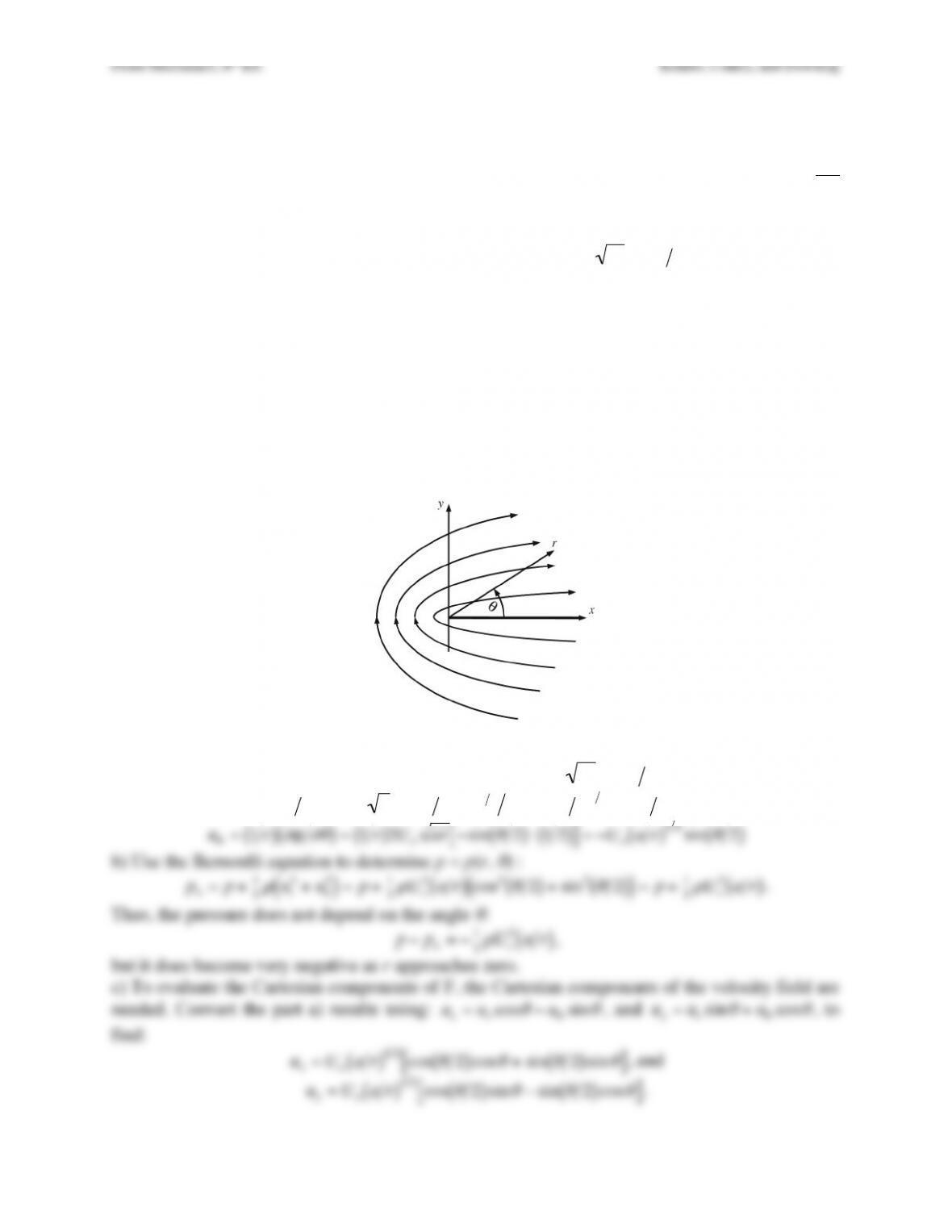
potential for flow around the tip of a flat plate that is coincident with the x-axis for x > 0. In two-
dimensional polar coordinates, this velocity potential is
φ
=2Uoar cos
θ
2
( )
where Uo and a are
velocity and length scales, respectively, that characterize the flow.
a) Determine ur and u
θ
, the radial and angular-directed velocity components, respectively.
b) If the pressure far from the origin is p∞, determine the pressure p at any location (r,
θ
).
c) Use the given potential, a circular control volume of radius
ε
centered at the origin of
coordinates, and the control volume version of the ideal flow momentum equation,
ρ
u(u⋅n)d
ξ
=
C
∫−pnd
ξ
C
∫+F
, to determine the force F (per unit depth into the page) that holds
the plate stationary when
ε
→0
. Here, n is the outward unit normal vector to the control volume
surface, and d
ξ
is the length increment of the circular control surface.
d) If the plate is released from rest, in what direction will it initially accelerate?
Solution 14.8. a) Directly differentiate the potential
φ
=2Uoar cos
θ
2
( )
.
ur=
∂φ ∂
r=2Uoacos
θ
2
( )
⋅r−1 2 2=Uoa r
( )
1 2 cos
θ
2
( )
, and
u
θ
=1r
( )
∂φ ∂θ
( )
=1r
( )
2Uoar −sin
θ
2
( )
⋅1 2
( )
[ ]
=−Uoa r
( )
1 2 sin
θ
2
( )
b) Use the Bernoulli equation to determine p = p(r,
θ
) :
p∞=p+1
2
ρ
ur
2+u
θ
2
( )
=p+1
2
ρ
Uo
2a r
( )
cos2
θ
2
( )
+sin2
θ
2
( )
( )
=p+1
2
ρ
Uo
2a r
( )
.
Thus, the pressure does not depend on the angle
θ
:
p−p∞=−1
2
ρ
Uo
2a r
( )
,
but it does become very negative as r approaches zero.
c) To evaluate the Cartesian components of F, the Cartesian components of the velocity field are
needed. Convert the part a) results using:
ux=urcos
θ
−u
θ
sin
θ
, and
uy=ursin
θ
+u
θ
cos
θ
, to
find:
ux=Uoa r
( )
1 2 cos
θ
2
( )
cos
θ
+sin
θ
2
( )
sin
θ
[ ]
, and
uy=Uoa r
( )
1 2 cos
θ
2
( )
sin
θ
−sin
θ
2
( )
cos
θ
[ ]
.
Fluid Mechanics, 6th Ed. Kundu, Cohen, and Dowling
These can be simplified to:
ux=Uoa r
( )
1 2 cos
θ
2
( )
, and
uy=Uoa r
( )
1 2 sin
θ
2
( )
, using
trigonometric identities. Here
n=er=excos
θ
+exsin
θ
, so
u⋅n=u⋅er=ur
. Thus, the CV
equation can be written in terms of x– and y-components:
ρ
uxex+uyey
( )
ur
ε
d
θ
0
2
π
∫=−p(excos
θ
+exsin
θ
)
ε
d
θ
0
2
π
∫+Fxex+Fyey
.
where d
ξ
=
ε
d
θ
. The pressure does not depend on
θ
, and the integrals of cos
θ
and sin
θ
from 0 to
2π are both zero so the pressure integration drops out leaving:
ρ
Uoa
ε
( )
1 2 cos
θ
2
( )
( )
Uoa
ε
( )
1 2 cos
θ
2
( )
ε
d
θ
0
2
π
∫=Fx
, and
ρ
Uoa
ε
( )
1 2 sin
θ
2
( )
( )
Uoa
ε
( )
1 2 cos
θ
2
( )
ε
d
θ
0
2
π
∫=Fy
.
The
ε
contour-radius factors cancel, so the integrands can be simplified to:
ρ
Uo
2acos2
θ
2
( )
d
θ
0
2
π
∫=Fx
, and
ρ
Uo
2asin
θ
2
( )
cos
θ
2
( )
d
θ
0
2
π
∫=Fy
.
Use the double-angle trigonometric identities to evaluate the integrals to find:
ρ
Uo
2a1
2
cos
θ
+1
( )
d
θ
0
2
π
∫=
πρ
Uo
2a=Fx
, and
ρ
Uo
2a1
2
sin
θ
( )
d
θ
0
2
π
∫=0=Fy
.
The fact that
ε
does not appear in either final answer suggests that the horizontal force, known as
leading edge suction, found in part d) will exist for any
ε
, even
ε
→0
. This force is applied to
the tip of the plate and arises from the singularity in the potential at r = 0.
Interestingly, the real-world effects of this singularity are exploited for both natural and
anthropogenic flight. The leading edges of real airfoils are rounded so that the flow remains
attached to the foil’s surface and does not have a singularity. Attached flow passing around a
finite-radius-of-curvature leading edge produces a leading-edge suction force of the size
predicted here that increases the lift and reduces the drag of real airfoils. The only superfluous
part of the above discussion and analysis is the limit
ε
→0
.
d) Fx holds the plate stationary by pushing it to the right. Therefore, if Fx is not applied, the plate
will accelerate to the left.
Fluid Mechanics, 6th Ed. Kundu, Cohen, and Dowling
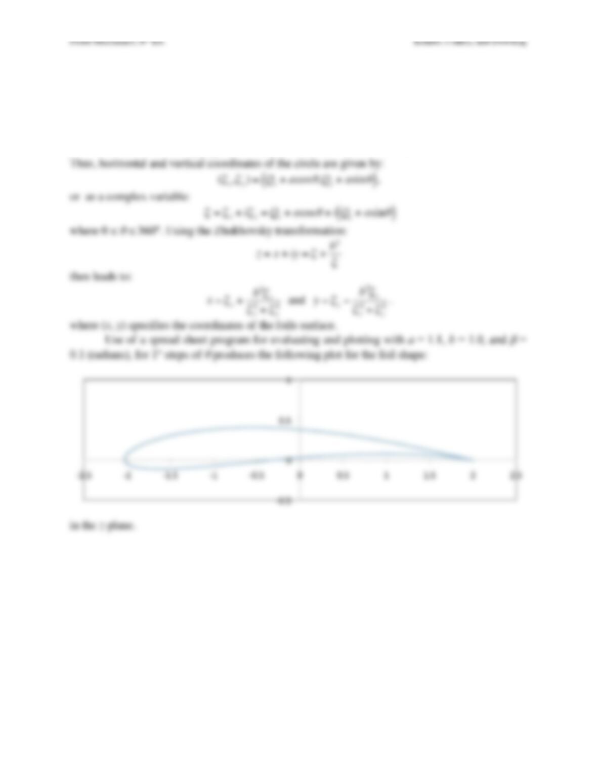
Exercise 14.9. Consider a cambered Zhukhovsky airfoil determined by the following
parameters: a = 1.1, b = 1.0, and
β
= 0.1. Using a computer, plot its contour by evaluating the
Zhukhovsky transformation. Also plot a few streamlines, assuming an angle of attack of 5°.
Solution 14.9. In the case the point Q at the center of the circle in the
ζ
-plane lies at:
(Qx,Qy)=(b−cos
β
,asin
β
)≅(−0.0945,0.1098)
.
Thus, horizontal and vertical coordinates of the circle are given by: