228 RADIATIVE HEAT TRANSFER
Solv-
ing the problem via GRAYDIFFXCH requires the following input, with results given below the code:

rr=0.1d0
A(1)=12*rr
EPS(1)=0.05
T(1)=0. ! T in K
! Surfaces 2 (oil tube)
HO(2)=2*rr/A(2)*qsun ! external irradiation
id(2)=1 ! T specified
! use loop for 3 different T2
DO k=1,3
T(2)= 200.+100*k ! T in K
! Fill PIN array with q and T
DO i=1,N
IF(id(i)==0) THEN
PIN(i)=q(i)
ELSEPIN(i)=sigma*T(i)**4 ! Convert temperatures to emissive powers
ENDIF
ENDDO
! View Factors; since configuration is open (iclsd=0), diagonal terms are needed
iclsd=0
F(1,1)=0.1994d0; F(1,2)=0.4003d0; F(2,2)=0.0000d0
! Solve system of equations for 3 T2:
CALL GRAYDIFF(N,iclsd,A,EPS,HO,F,ID,PIN,POUT)
! Output
! Convert emissive powers to temperatures
sumq=0 ! Check total flux=0?
rr=0.1d0
A(1)=12*rr ! per unit depth
id(1)=1 ! T specified
A(2)=2*pi*rr ! per unit depth
id(2)=1 ! T specified
! use loop for 3 different T2
DO k=1,3
T(2)= 200.+100*k ! T in K
! View Factors; since configuration is open (iclsd=2), diagonal terms are also needed

232 RADIATIVE HEAT TRANSFER
7.14
R = 40 cm R
A2: 2 = 0.1, q2 = 0
∋
r=25 cm
h=30 cm
L=30 cm
A1: 1 = 0.8, Q1 = -0.4 kW
∋
Q
s
=10 kW
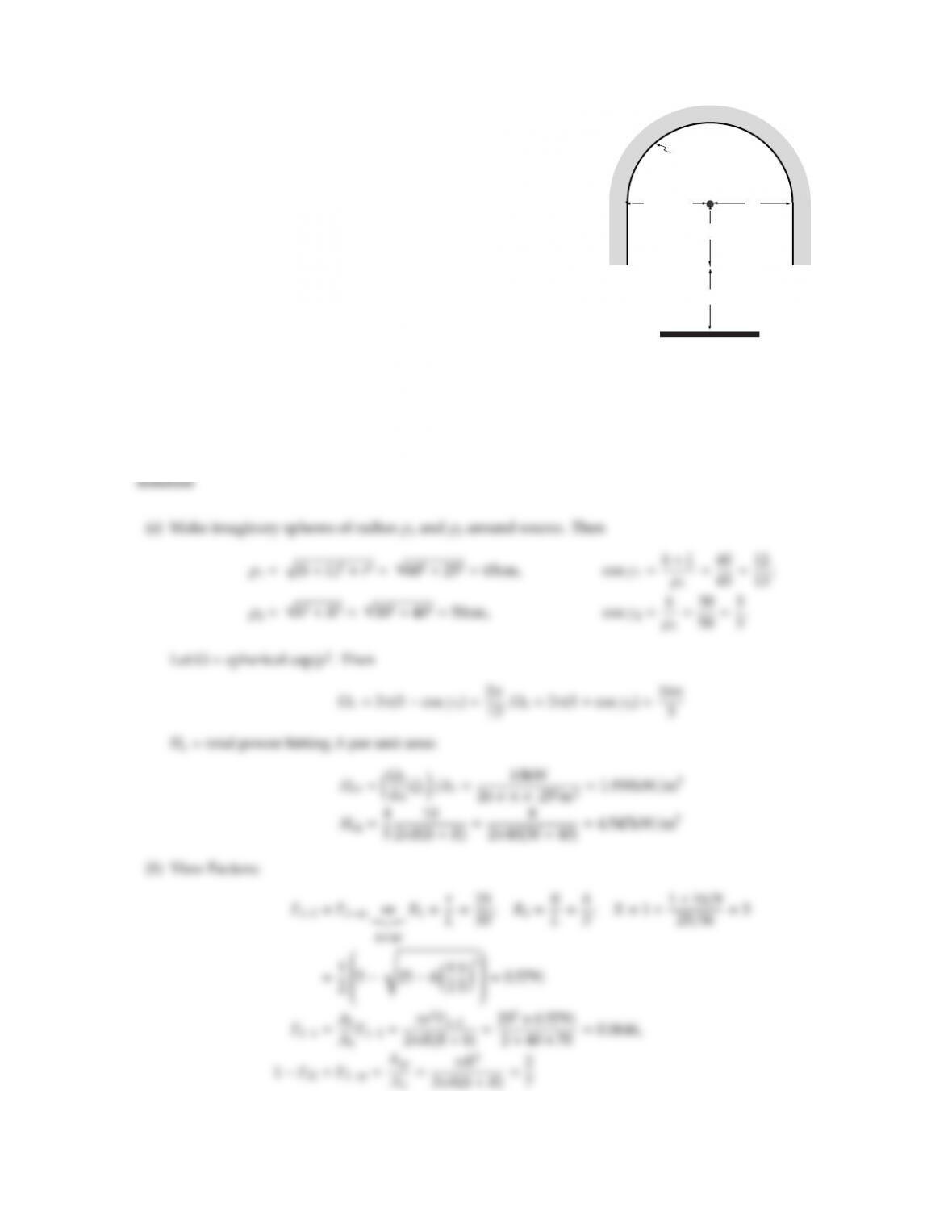
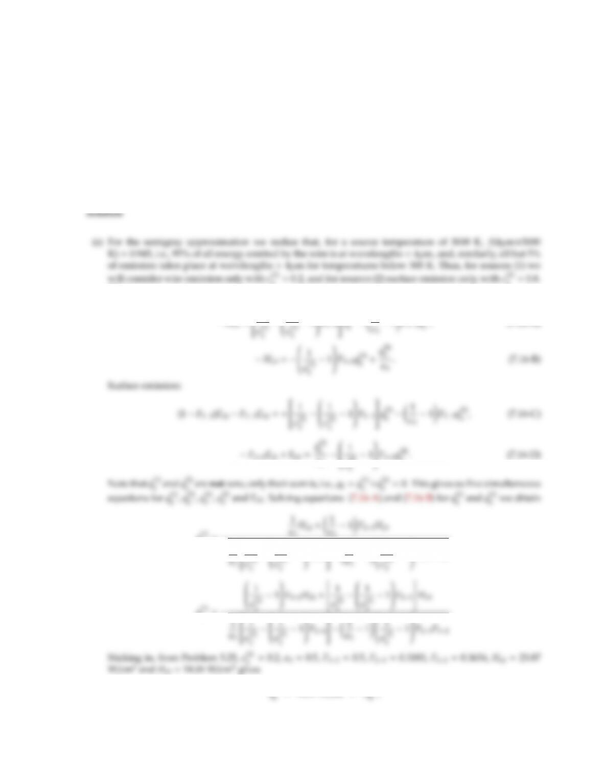
A small spherical heat source outputting Qs=10 kW power,
spreading equally into all directions, is encased in a reflector as
shown, consisting of a hemisphere of radius R=40 cm, plus a
ring of radius Rand height h=30 cm. The arrangement is used
to heat a disk of radius =25 cm a distance of L=30 cm below
the reflector. Reflector A2is gray and diffuse with emittance of
ǫ2=0.1 and is insulated. Disk A1is diffuse and coated with a
selective absorber, i.e.,
ǫ1λ=0.8,0≤λ < 3µm,
0.2,3µm<λ<∞.
The source is of the tungsten–halogen type, i.e., the spectral vari-
ation of its emissive power follows that of a blackbody at 4000 K.
(a) Determine (per unit area of receiving surface) the irradiation from heat source to reflector and to disk;
(b) Determine all relevant view factors;
(c) Outline how you would obtain the temperature of the disk, if 0.4 kW of power is extracted from it.
(“Outline” implies setting up all the necessary equations, plus a sentence on how you would solve
them.)
0.2(1 −f)≈0.8, and one may assume that all of Ho1is below 3µm. Then
0=q1
1
1
2+Ho1
2. Surface emission
Eb1−F1−2Eb2=q2
1
1
2
1
234 RADIATIVE HEAT TRANSFER
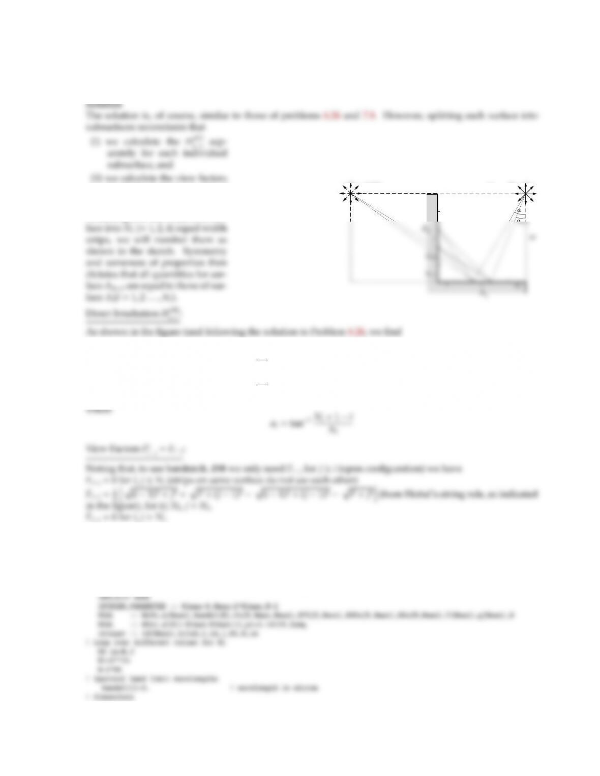
7.15 Repeat Problem 7.8 using subroutine bandapp of Appendix F (or modifying the sample program bandmodelxch).
Break up each surface into Nsubsurfaces of equal width (n=1,2,4,8).
for all the individual pairs of
strips.
Assuming that we break each sur–
w
S´
S´
(2)
2Ni
n+1
n
Hs(1)
o−i=S′
2πhθi+ρs(1)θi(1)i
=S′
2πh(αi−αi+1)+ρs(1)(α1−i−α2−i)i,
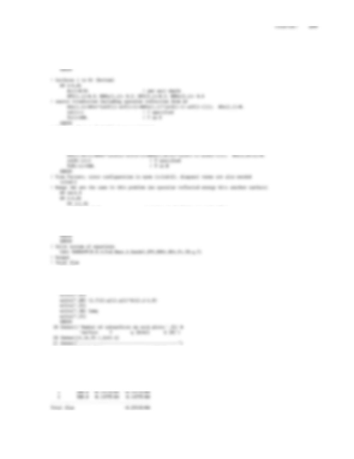
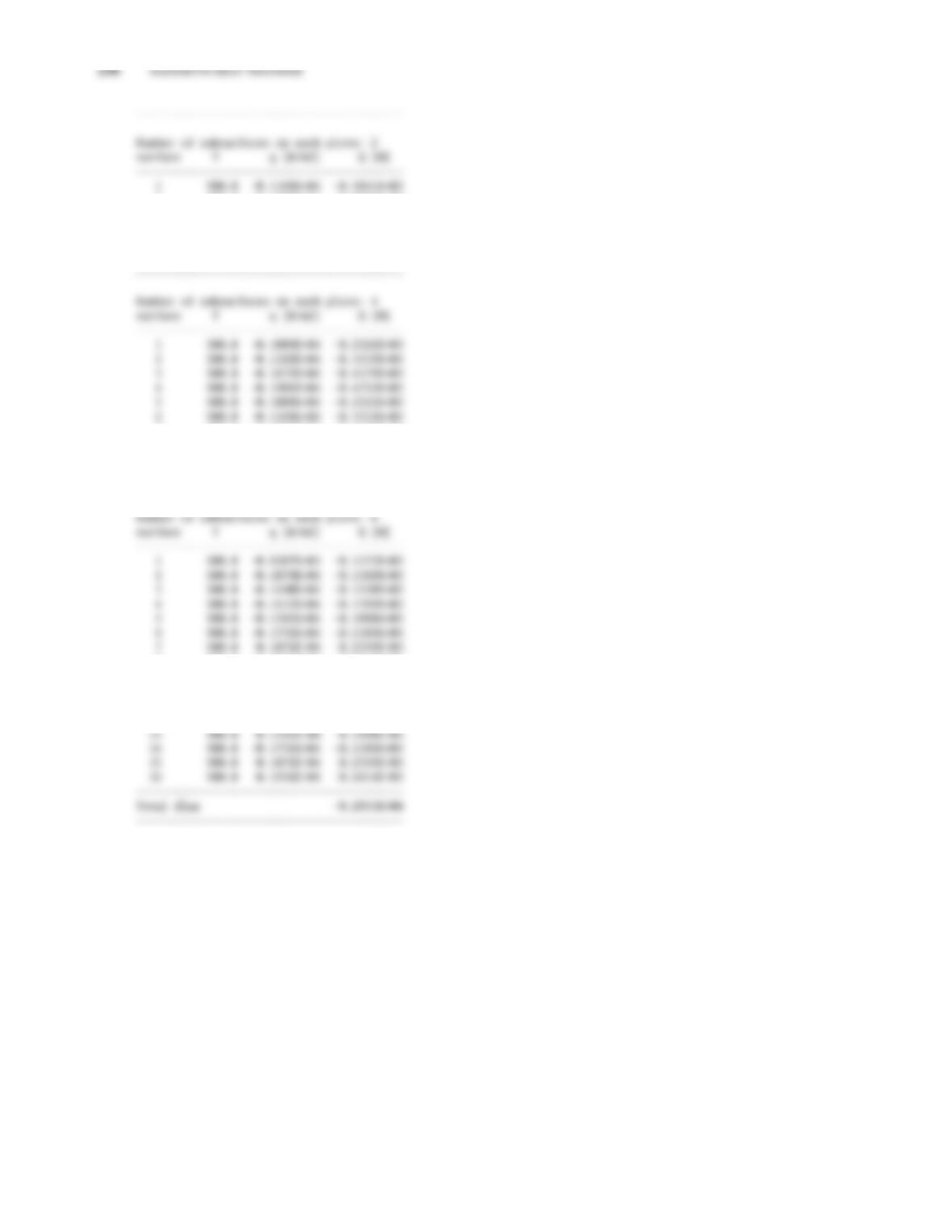
The corresponding modified version of bandmxch.f90 is shown below, together with the heat flux results for
Ni=1, 2, 4 and 8. As expected, it is seen that – for increasing Ni– the strips closest to the line source have to
remove more heat than those close to the corner.
PROGRAM BANDMpr7_11
! Program to solve Problem 7.11; does not take advantage of symmetry
W=1.
HOst=20000./(2.*pi)*Ni/W
! Angle with which Ni surfaces are seen from S
DO i=1-Ni,Ni+1
alf(i)=atan(FLOAT(Ni+1-i)/Ni)
! Surfaces Ni+1 to N (left) (same as bottom)
DO i=1,Ni
A(Ni+i)=W/Ni ! per unit depth
EPS(1,Ni+i)=0.8; RHOs(1,Ni+i)= 0.2; EPS(2,Ni+i)=0.2; RHOs(2,Ni+i)= 0.8
! source irradiation including specular reflection from A2
Fs(im,i,j)=0. ! strips on A1 don’t see each other
Fs(im,i,Ni+j)=(sqrt(FLOAT((i-1)**2+j**2))+sqrt(FLOAT(i**2+(j-1)**2)) &
-sqrt(FLOAT((i-1)**2+(j-1)**2))-sqrt(FLOAT(i**2+j**2)))/2.
Fs(im,Ni+i,Ni+j)=0.
ENDDO
Sumq=0.
DO i=1,N
Sumq=Sumq+q(i)*A(i)
ENDDO
write(*,10) Ni
30 format(’Total flux ’,e13.4)
stop
end
Number of subsurfaces on each plate: 1
surface T q [W/m2] Q [W]
——————————————
2 500.0 -0.1786E+04 -0.8932E+03
3 500.0 -0.1168E+04 -0.5841E+03
4 500.0 -0.1786E+04 -0.8932E+03
——————————————
Total flux -0.2955E+04
7 500.0 -0.1671E+04 -0.4179E+03
8 500.0 -0.1901E+04 -0.4753E+03
——————————————
Total flux -0.2955E+04
——————————————
8 500.0 -0.1931E+04 -0.2414E+03
9 500.0 -0.9387E+03 -0.1173E+03
10 500.0 -0.1079E+04 -0.1349E+03
11 500.0 -0.1240E+04 -0.1550E+03
12 500.0 -0.1415E+04 -0.1769E+03
CHAPTER 7 237
7.16 Repeat Problem 5.25 for the case that the insulated cylinder is coated with a material that has
ǫ2λ=0.2,0≤λ < 4µm,
0.8,4µm<λ<∞
(the flat surface remains gray with ǫ3=0.5). Note that the wire heater is gray and diffuse and at a temperature
of T1=3000 K.
(a) Find the solution using the semigray method; also set up the same problem and find the solution by
using program semigrayxchdf.
(b) Set up the solution using the band approximation, i.e., to the point of having a set of simultaneous
equations and an outline of how to solve them. Also find the solution using program bandmxchdf.
2=0.2, and for sources (2) surface emission only, with ǫ(2)
2=0.8.
Thus,
Wire emission:
−Ho2=
1
1
2−1
3,(7.16-A)
−F3−2Eb2+Eb3=q(2)
ǫ3−
ǫ(2)
2.(7.16-D)
q(1)
2=−
1
1
1
1
,
q(1)
238 RADIATIVE HEAT TRANSFER
ǫ3
(1 −F2−2−F2−3F3−2)+F2−3F3−2
And the total flux is q3=−15.11 −3.61 =−18.72 W/cm2, which is the same as for a gray surface.
However, in order to reemit the absorbed source radiation (same in both cases), the surface must be a lot
PROGRAM SEMIGRXCHDF
IMPLICIT NONE
INTEGER,PARAMETER :: N=2
DOUBLE PRECISION :: A(N),F(N,N),EPS(2,N),HO(N),T(N),q(N),L1,L2
integer :: id(N),iclsd,i
! Dimensions
L1=3.1416*0.02
A(1)=L1 ! per unit depth
id(1)=0 ! q specified
A(2)=L2 ! per unit depth
id(2)=1 ! T specified
T(2)=300.D0 ! T in K
! View Factors; since configuration is open (iclsd=2), diagonal terms are also needed
iclsd=2
! Range 1&2 have same Fij for diffuse surfaces
F(1,1)=0.3634; F(1,2)=0.3183; F(2,2)=0.;
1 1307.2 0.0000E+00 0.0000E+00
2 300.0 -0.1872E+06 -0.7487E+04
More accurately, one should use emissive-power-weighted emittances, with ǫ1evaluated at 3000 K,
and ǫ2evaluated at a temperature close to the unknown T2(emission from A3at 300 K will be pretty
negligible). Thus, replacing the EPS line by
i=2 : (1 −F2−2)Eb2f2(λcT2)−F2−3Eb3f3(λcT3)=
1
ǫ(1)
1
ǫ(1)
2−1
ǫ3−1q(1)
3+Ho2f1(λcT1)
1
3
i=2 : (1 −F2−2)Eb2(1 −f2)−F2−3Eb3(1 −f3)=
ǫ(2)
2−
ǫ(2)
2−1F2−2q(2)
2−1
ǫ3−1q(2)
3+Ho2(1 −f1)
1
3
2. However, the relations are nonlinear in T(or rather, T4) because of the f(λcT) terms. Therefore,
aT2must be guessed and updated until q2≃0. The necessary changes in bandmxch.f90 and its output
are given below:
L2=0.04
! Surface 1 (cylinder A2)
A(1)=L1 ! per unit depth
q(1)= 0. ! q in W/m2
! Surface2 (top A3)
A(2)=L2 ! per unit depth
T(2)=300. ! T in K
! View Factors; since configuration is open (iclsd=2), diagonal terms are also needed
iclsd=2
! Range 1&2 have same Fij for diffuse surfaces
F(1,1)=0.3634; F(1,2)=0.3183; F(2,2)=0.;