9-139
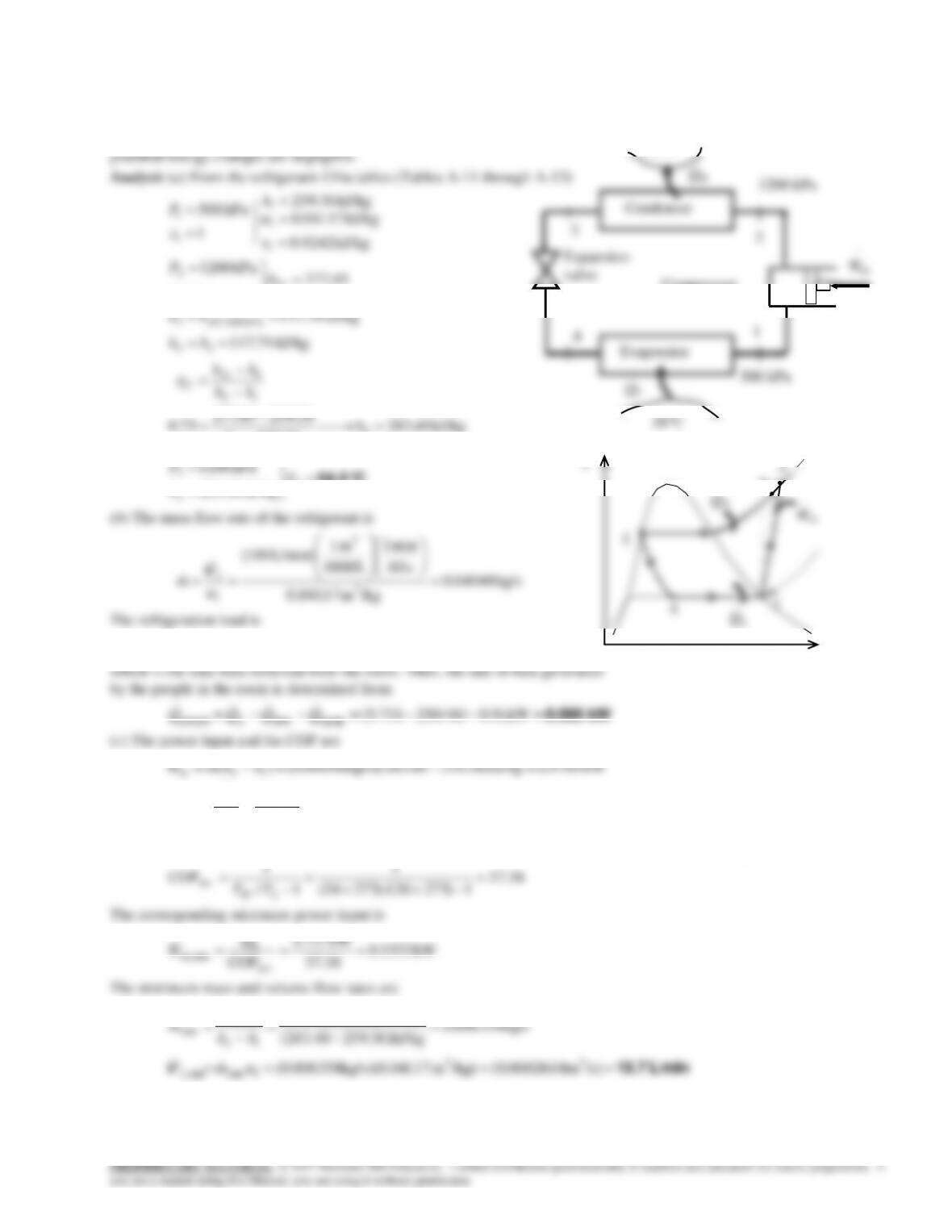
kJ 7077.0kJ/kg88.2301703.6kg) 0004805.0()( 14out uumQ
0.528 kJ 1.5
kJ 0.792
in
outnet,
th Q
W
(c) The mean effective pressure is determined to be
kPa 1761
kJ
mkPa
m)000045.0000495.0(
kJ 0.7923
MEP
3
3
21
outnet,
VV
W
(d) The power for engine speed of 3000 rpm is
kW 79.2
s 60
min 1
rev/cycle) 2(
rev/min) 3000(
cycle)–rkJ/cylinde 0.792cylinder)( 4(
rev
netcylnet n
n
WnW
Note that there are two revolutions in one cycle in four-stroke engines.

9-141
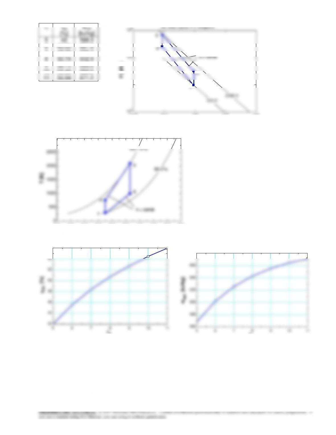
9-174 Problem 9-173 is reconsidered. The effect of the compression ratio net work done and the efficiency of the
cycle is to be investigated. Also, the T–s and P–
v
diagrams for the cycle are to be plotted.
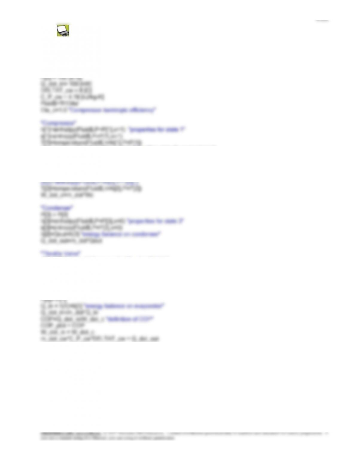
Analysis Using EES, the problem is solved as follows:
“Input Data”
R=0.287 [kJ/kg-K]
“Conservation of energy for process 1 to 2: no heat transfer (s=const.) with work input”
w_in = DELTAu_12
DELTAu_12=intenergy(air,T=T[2])-intenergy(air,T=T[1])
“Process 2-3 is constant volume heat addition”
P[4]*v[4]/T[4]=P[3]*v[3]/T[3]
{P[4]*v[4]=R*T[4]}
“Conservation of energy for process 3 to 4: no heat transfer (s=const) with work output”
– w_out = DELTAu_34
DELTAu_34=intenergy(air,T=T[4])-intenergy(air,T=T[3])
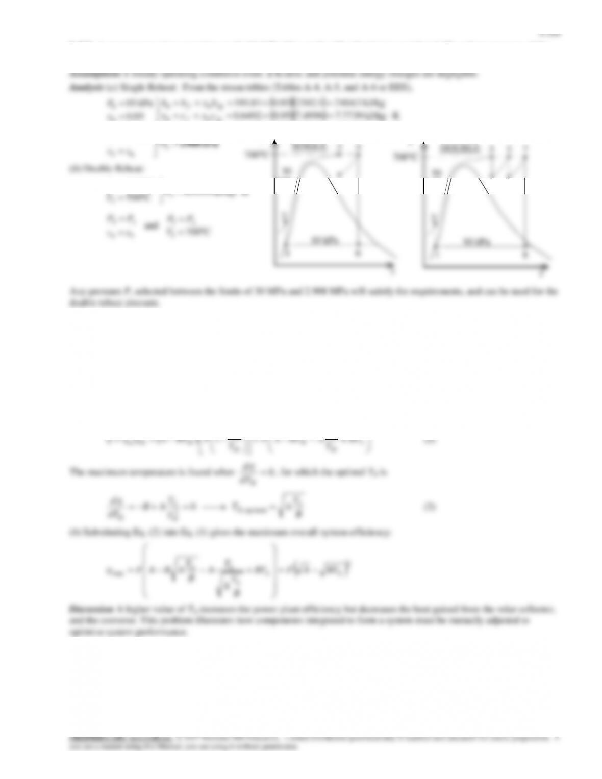
9-142
rv
th
[%]
wnet
[kJ/kg]
5
6
7
8
9
10
11
42
45.55
48.39
50.74
52.73
54.44
55.94
568.3
601.9
625.7
642.9
655.5
664.6
671.2
4.0 4.5 5.0 5.5 6.0 6.5 7.0 7.5 8.0 8.5
0
500
1000
1500
2000
2500
3000
s [kJ/kg-K]
T [K]
98 kPa
6971 kPa
Air Otto Cycle T-s Diagram
1
2
3
4
v = const
5 6 7 8 9 10 11
42
44
46
48
50
52
54
56
rv
th [%]
10-2 10-1 100101102
102
103
104
v [m3/kg]
P [kPa]
2
3
4
s = const
Air Otto Cycle P-v Diagram
5 6 7 8 9 10 11
560
580
600
620
640
660
680
rv
wnet [kJ/kg]
9-143
9-175 The compression ratio required for an ideal Otto cycle to produce certain amount of work when consuming a given
amount of fuel is to be determined.
Assumptions 1 The air-standard assumptions are applicable. 2 Kinetic and potential energy changes are negligible. 3 Air is
9-144
9-176E An ideal dual cycle with air as the working fluid with a compression ratio of 12 is considered. The thermal
efficiency of the cycle is to be determined.
A-2E).
Analysis The mass of air is
lbm 003881.0
R 580R/lbmftpsia 0.3704
ft 98/1728psia 14.7
3
3
1
11
RT
P
m
V
P
3
1.1 Btu
x
9-145
9-177 A regenerative Brayton cycle with helium as the working fluid is considered. The thermal efficiency and the required
mass flow rate of helium are to be determined for 100 percent and 80 percent isentropic efficiencies for both the compressor
and the turbine.
Assumptions 1 The air-standard assumptions are applicable. 2 Kinetic and potential energy changes are negligible. 3
Helium is an ideal gas with constant specific heats.
9-146
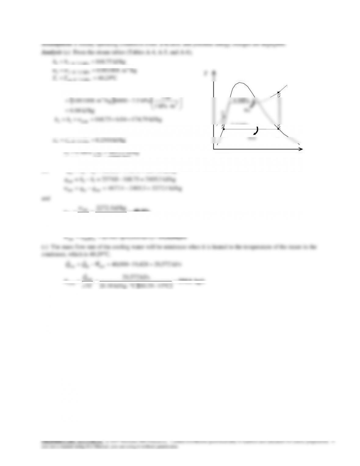
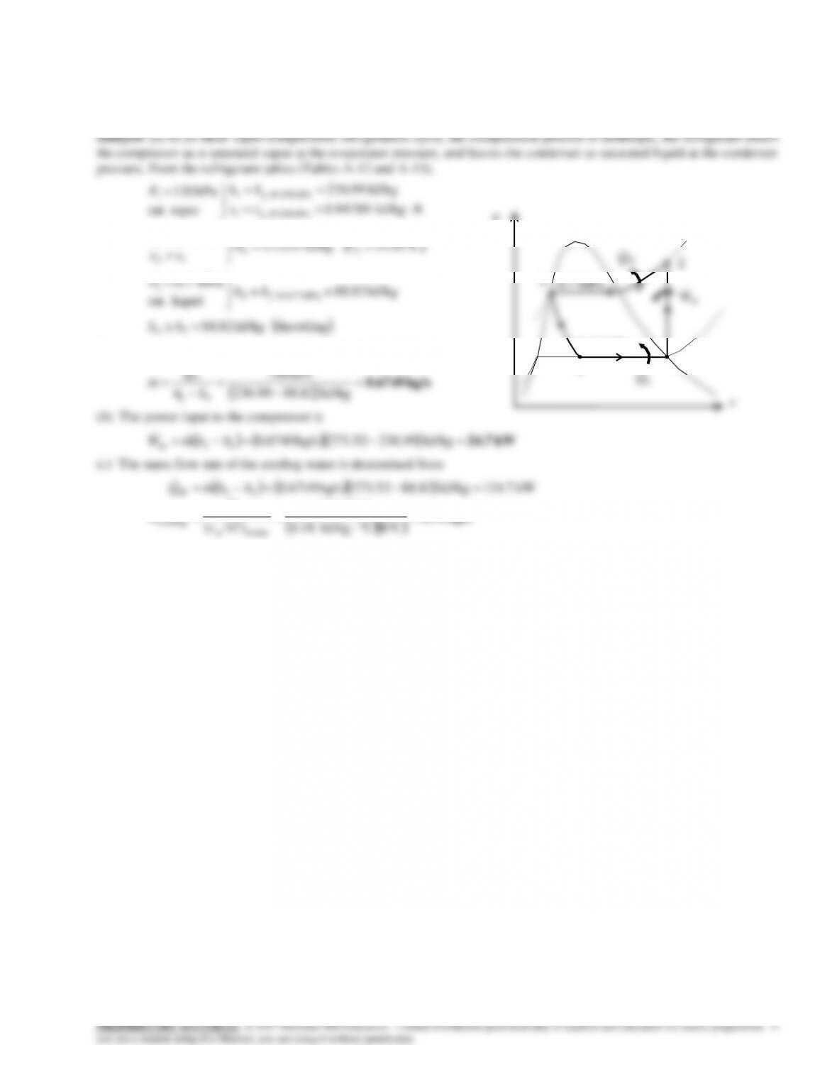
9-178 A steam power plant operates on the simple ideal Rankine cycle. The turbine inlet temperature, the net power output,
the thermal efficiency, and the minimum mass flow rate of the cooling water required are to be determined.
kJ/kg 2501.8
kJ/kg 0.2574
kJ/kg 79.17404.675.168
kJ/kg 6.04 mkPa 1
kJ 1
kPa 7.56000/kgm 0.001008
C29.40
/kgm 001008.0
kJ/kg 75.168
kPa 5.7 @ 4
kPa 5.7 @ 4
inp,12
3
3
121inp,
kPa 7.5 @ sat1
3
kPa 5.7 @ 1
kPa 5.7 @ 1
g
g
f
f
ss
hh
whh
PPw
TT
hh
v
vv
C1089.2
3
3
43
3kJ/kg 2.4852
MPa 6
T
h
ss
P
(b)
kJ/kg 1.22723.24054.4677
kJ/kg 3.240575.1680.2574
kJ/kg 4.467779.1742.4852
outinnet
14out
23in
qqw
hhq
hhq
48.6% kJ/kg 4677.4
kJ/kg 2272.1
in
net
th q
w
Thus,
qin
qout
7.5 kPa
1
3
2
4
6 MPa
s
T
9-148
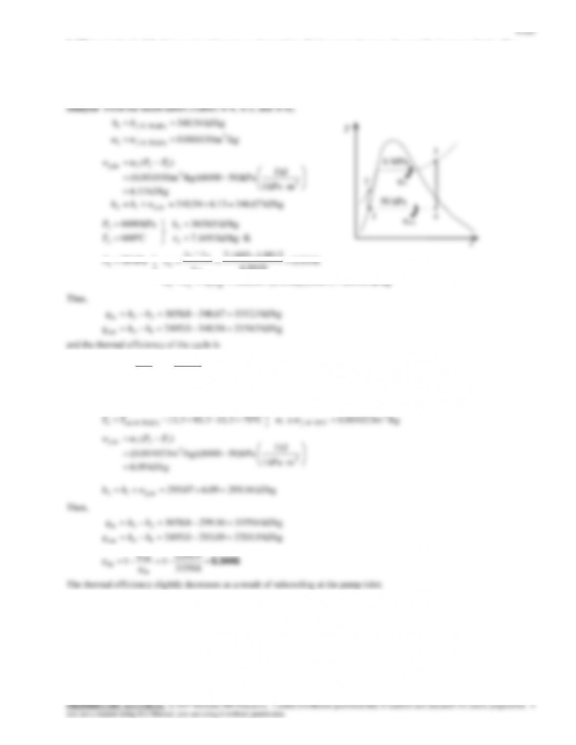
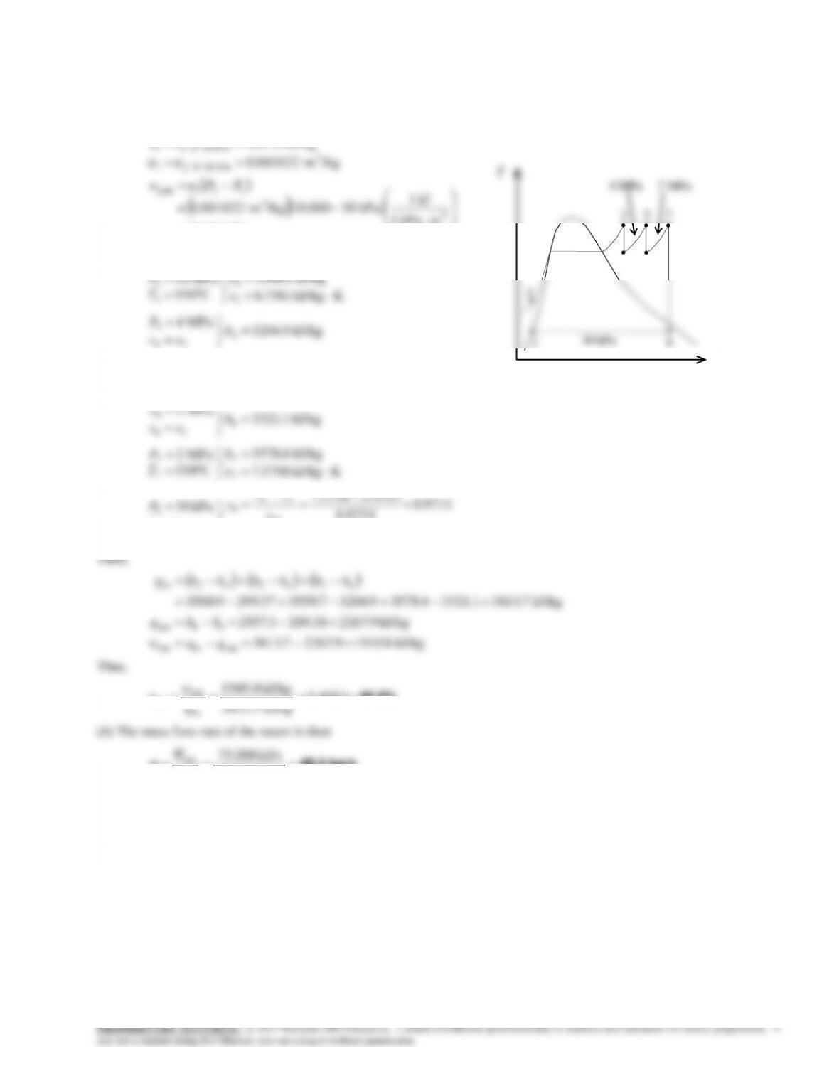
9-180 A steam power plant operating on an ideal Rankine cycle with two stages of reheat is considered. The thermal
efficiency of the cycle and the mass flow rate of the steam are to be determined.
Assumptions 1 Steady operating conditions exist. 2 Kinetic and potential energy changes are negligible.
Analysis (a) From the steam tables (Tables A-4, A-5, and A-6),
kJ/kg 37.29919.1018.289
kJ/kg .1910 mkPa 1
kJ 1
kPa 3010,000/kgm 0.001022
/kgm 001022.0
kJ/kg 18.289
inp,12
3
3
121inp,
3
kPa 30 @ 1
kPa 30 @ 1
whh
PPw
hh
f
f
v
vv
kJ/kg 1.25573.23359711.027.289
9711.0
8234.6
9441.05706.7
kPa 30
KkJ/kg 5706.7
kJ/kg 4.3578
C550
MPa 2
kJ/kg 1.3321
MPa 2
KkJ/kg 2335.7
kJ/kg 7.3559
C550
MPa 4
kJ/kg 9.3204
MPa 4
KkJ/kg 7561.6
kJ/kg 9.3500
C550
MPa 10
88
8
8
78
8
7
7
7
7
6
56
6
5
5
5
5
4
34
4
3
3
3
3
fgf
fg
f
hxhh
s
ss
x
ss
P
s
h
T
P
h
ss
P
s
h
T
P
h
ss
P
s
h
T
P
Then,
kJ/kg 8.15459.22677.3813
kJ/kg 9.226718.2891.2557
kJ/kg 7.38131.33214.35789.32047.355937.2999.3500
outinnet
18out
674523in
qqw
hhq
hhhhhhq
Thus,
40.5% 4053.0
kJ/kg 3813.7
kJ/kg 1545.8
in
net
th q
w
kg/s 48.5 kJ/kg 1545.8
kJ/s 75,000
net
net
w
W
m
1
5
2
8
s
T
3
4
10 MPa
30 kPa
7
6
4 MPa
2 MPa
9-150
9-183 A house is cooled adequately by a 3.5 ton air-conditioning unit. The rate of heat gain of the house when the air–
conditioner is running continuously is to be determined.
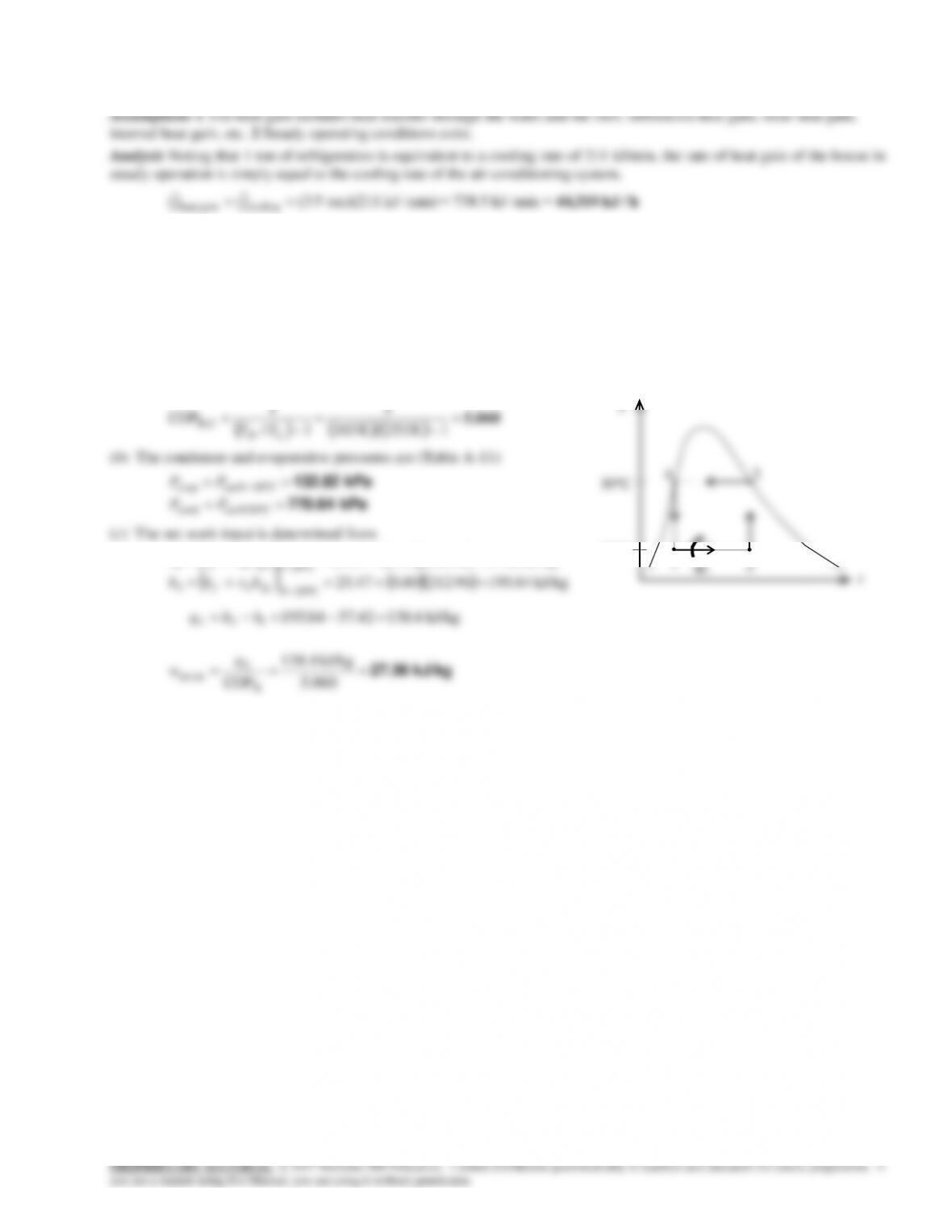
9-184 A steady-flow Carnot refrigeration cycle with refrigerant-134a as the working fluid is considered. The COP, the
condenser and evaporator pressures, and the net work input are to be determined.
Assumptions 1 Steady operating conditions exist. 2 Kinetic and potential energy changes are negligible.
Analysis (a) The COP of this refrigeration cycle is determined from
5.060
1K 253/K 303
1
1/
1
COP CR,
LH TT
(b) The condenser and evaporative pressures are (Table A–11)
kPa 770.64
kPa 132.82
C03@satcond
C20@satevap
PP
PP
(c) The net work input is determined from
kJ/kg 42.5796.21215.047.25
C20@
11
fgf
hxhh
kJ/kg 27.36
060.5
kJ/kg 138.4
COP
R
innet,
L
q
w
T
qL
1
2
3
4
30C
–20C
9-151
9-185 A heat pump water heater has a COP of 3.4 and consumes 6 kW when running. It is to be determined if this heat
pump can be used to meet the cooling needs of a room by absorbing heat from it.
Assumptions The COP of the heat pump remains constant whether heat is absorbed from the outdoor air or room air.
Analysis The COP of the heat pump is given to be 3.4. Then the COP of the air-conditioning system becomes
Then the rate of cooling (heat absorption from the air) becomes
9-152
9-187 A large refrigeration plant that operates on the ideal vapor-compression cycle with refrigerant-134a as the working
fluid is considered. The mass flow rate of the refrigerant, the power input to the compressor, and the mass flow rate of the
cooling water are to be determined.
Assumptions 1 Steady operating conditions exist. 2 Kinetic and potential energy changes are negligible.
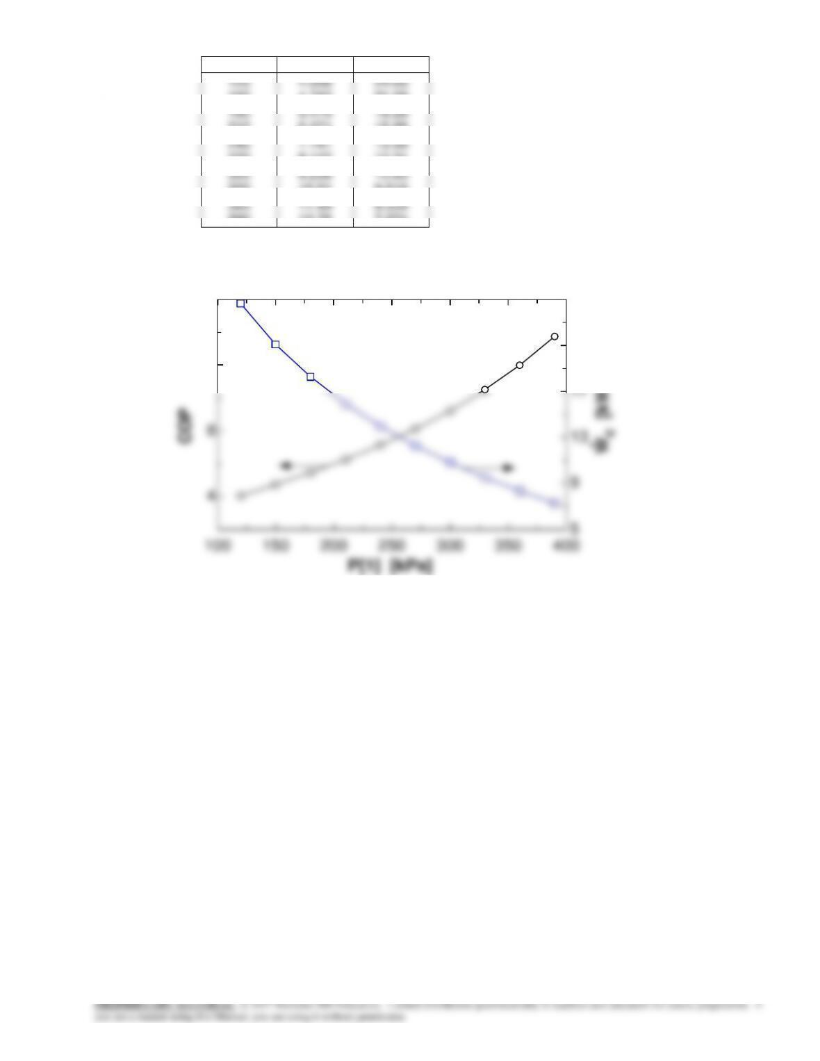
9-154
P1 [kPa]
COP
WC [kW]
120
150
180
210
240
270
300
330
360
390
4.056
4.743
5.475
6.271
7.147
8.127
9.236
10.51
11.99
13.75
24.65
21.08
18.26
15.95
13.99
12.31
10.83
9.516
8.339
7.274
100 150 200 250 300 350 400
4
8
12
16
5
9
13
17
21
25
P[1] [kPa]
COP
Wc [kW]
9-155
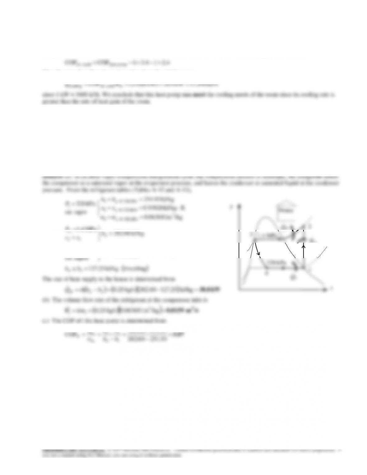
9-189 An air-conditioner with refrigerant-134a as the refrigerant is considered. The temperature of the refrigerant at the
compressor exit, the rate of heat generated by the people in the room, the COP of the air-conditioner, and the minimum
volume flow rate of the refrigerant at the compressor inlet are to be determined.
Assumptions 1 Steady operating conditions exist. 2 Kinetic and
26°C
34°C
9-156