9-41
9-56 A four-cylinder ideal diesel engine with nitrogen as the working fluid has a compression ratio of 22 and a cutoff ratio
of 1.8. The power the engine will deliver at 2300 rpm is to be determined.
Assumptions 1 The air-standard assumptions are applicable with nitrogen as the working fluid. 2 Kinetic and potential
energy changes are negligible. 3 Nitrogen is an ideal gas with constant specific heats.
Properties The properties of nitrogen at room temperature are cp = 1.039 kJ/kg·K, c
v
= 0.743 kJ/kg·K, R = 0.2968
kJ/kg·K, and k = 1.4 (Table A-2).
9-42
9-57E An ideal dual cycle has a compression ratio of 15 and cutoff ratio of 1.4. The net work, heat addition, and the thermal
efficiency are to be determined.
c
v
= 0.171 Btu/lbm·R, and k = 1.4 (Table A-2Ea).
Analysis Working around the cycle, the germane properties at the various states are
1
1
1
k
k
v
2
v
psia 1.692psia) 2.629)(1.1(
23 PrPP px
psia 692.1
P
4
1
2
qout

9-45
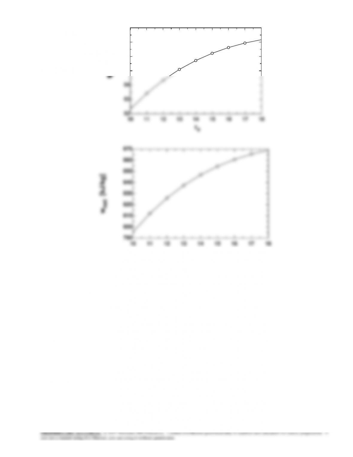
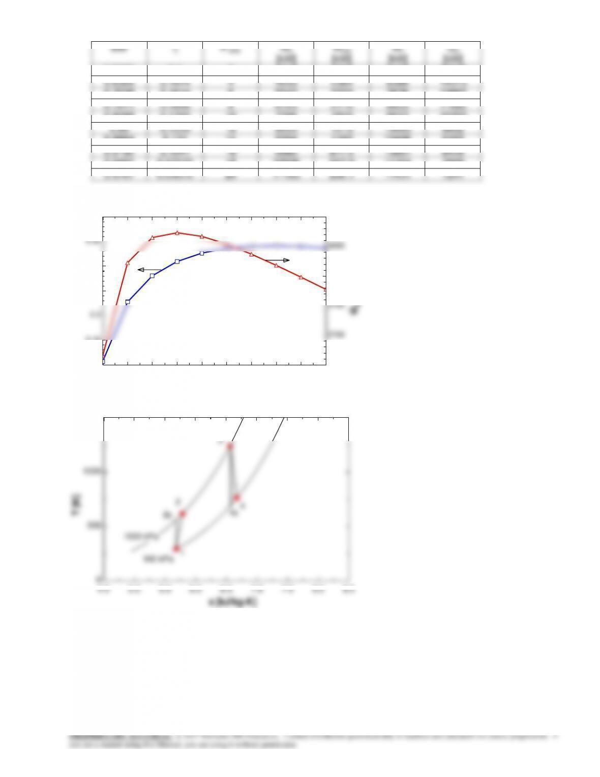
rv
th [%]
wnet [kJ/kg]
10
52.33
795.4
11
53.43
812.1
12
54.34
826
13
55.09
837.4
14
55.72
846.9
15
56.22
854.6
16
56.63
860.7
17
56.94
865.5
18
57.17
869
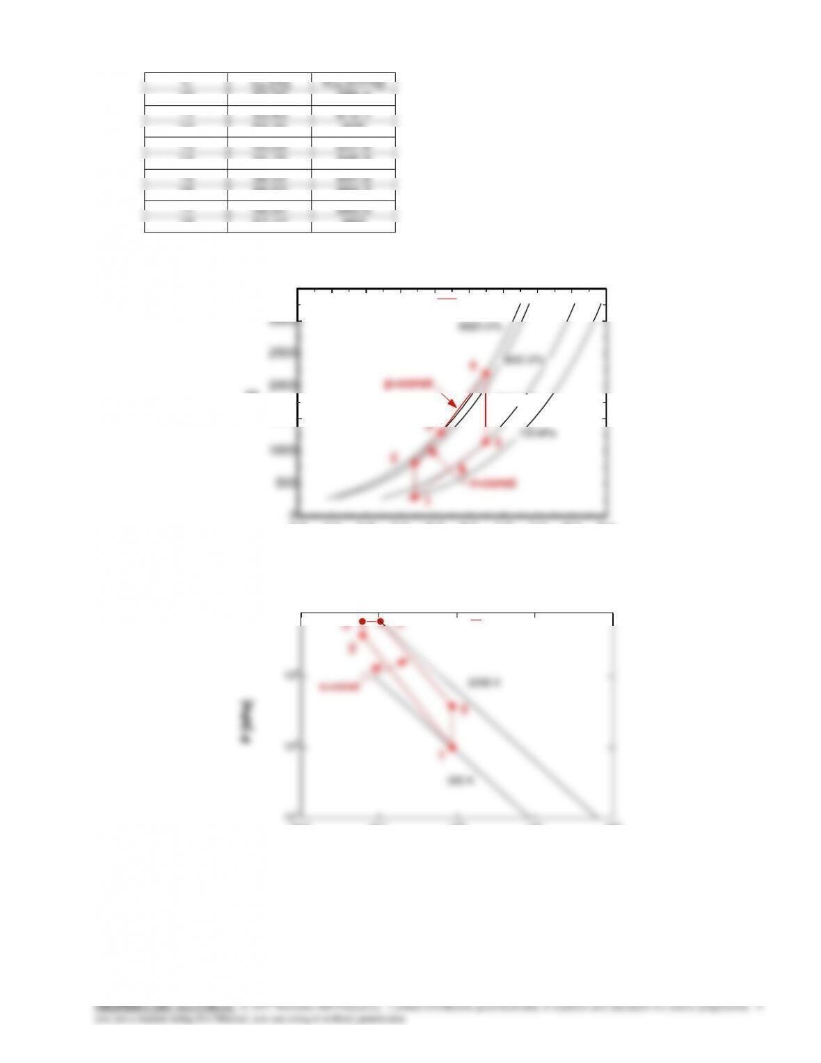
4.0 4.5 5.0 5.5 6.0 6.5 7.0 7.5 8.0 8.5
0
500
1000
1500
2000
2500
3000
3500
s [kJ/kg-K]
T [K]
100 kPa
382.7 kPa
3842 kPa
6025 kPa
T-s Diagram for Air Dual Cycle
1
2
3
4
5
v=const
p=const
10-2 10-1 100101102
101
102
103
8x10³
v [m3/kg]
P [kPa]
300 K
2200 K
P-v Diagram for Air Dual Cycle
1
2
34
5
s=const
9-46
10 11 12 13 14 15 16 17 18
52
53
54
55
56
57
58
rv
th [%]
10 11 12 13 14 15 16 17 18
790
800
810
820
830
840
850
860
870
rv
wnet [kJ/kg]
9-50
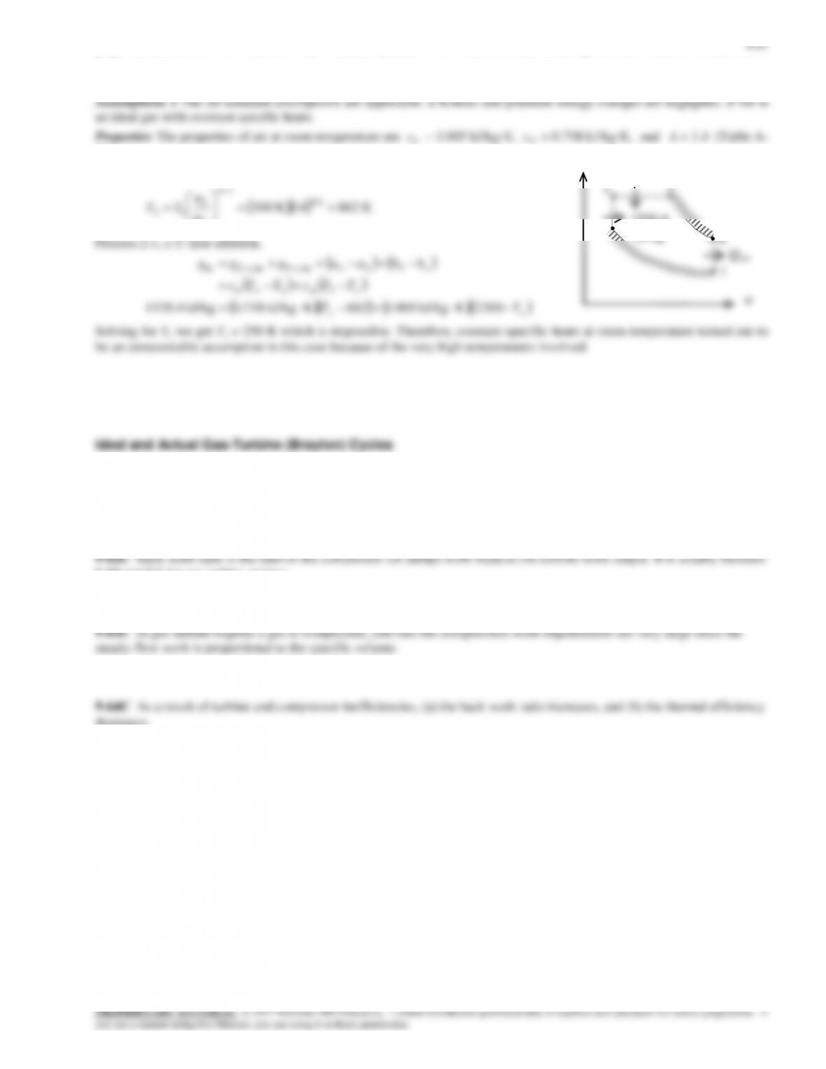
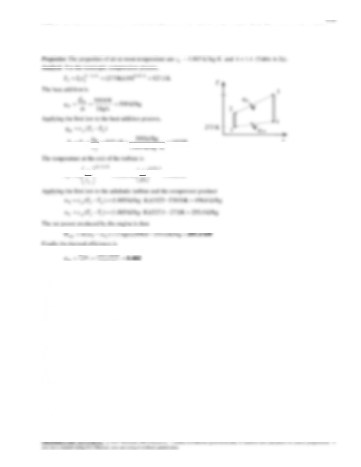
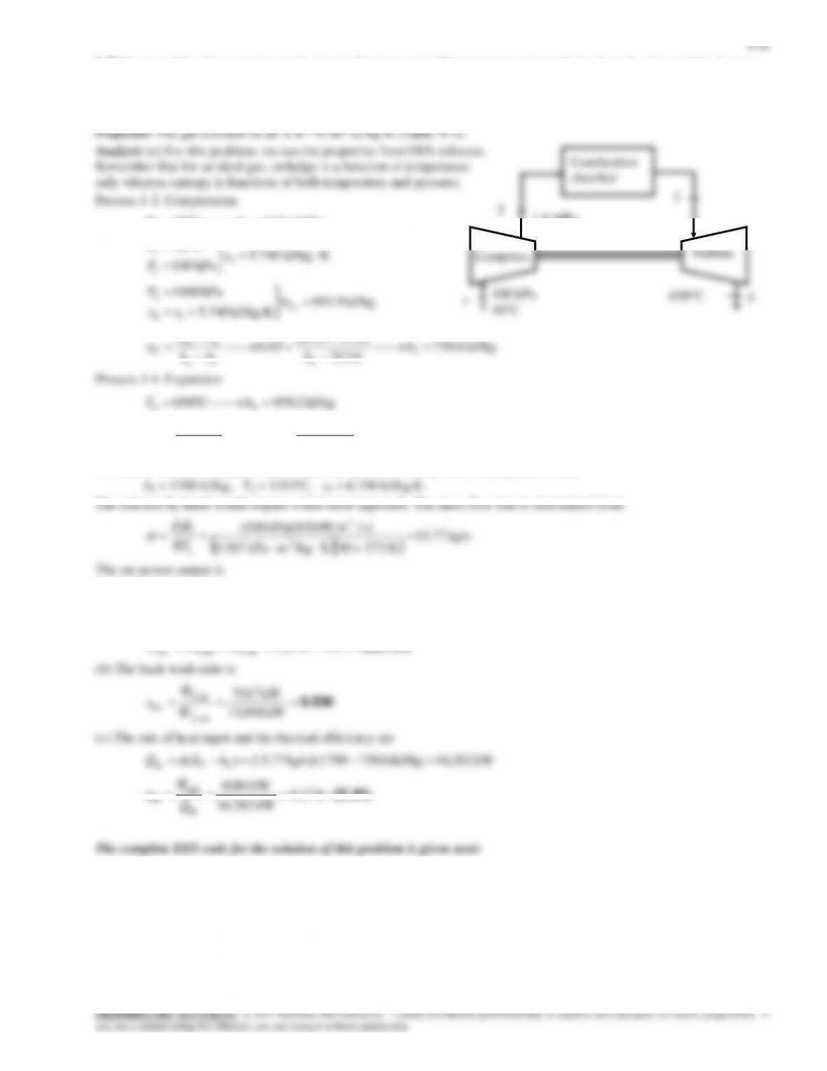
9-68 A simple Brayton cycle with air as the working fluid has a pressure ratio of 10. The air temperature at the turbine exit,
the net work output, and the thermal efficiency are to be determined.
Assumptions 1 Steady operating conditions exist. 2 The air-standard
assumptions are applicable. 3 Kinetic and potential energy changes are
T
3

9-52
Bwr
Pratio
Wc
[kW]
Wnet
[kW]
Wt
[kW]
Qin
[kW]
0.5229
0.1
2
1818
1659
3477
16587
0.6305
0.1644
4
4033
2364
6396
14373
0.7038
0.1814
6
5543
2333
7876
12862
0.7611
0.1806
8
6723
2110
8833
11682
0.8088
0.1702
10
7705
1822
9527
10700
0.85
0.1533
12
8553
1510
10063
9852
0.8864
0.131
14
9304
1192
10496
9102
0.9192
0.1041
16
9980
877.2
10857
8426
0.9491
0.07272
18
10596
567.9
11164
7809
0.9767
0.03675
20
11165
266.1
11431
7241
2 4 6 8 10 12 14 16 18 20
0.12
0.16
0.2
0.24
0.28
0.32
0.36
2250
2700
3150
3600
4050
4500
Pratio
Wnet [kW]
4.5 5.0 5.5 6.0 6.5 7.0 7.5 8.0 8.5
0
500
1000
1500
T [K]
100 kPa
1000 kPa
Air
1
2
3
4
2s 4s
9-53
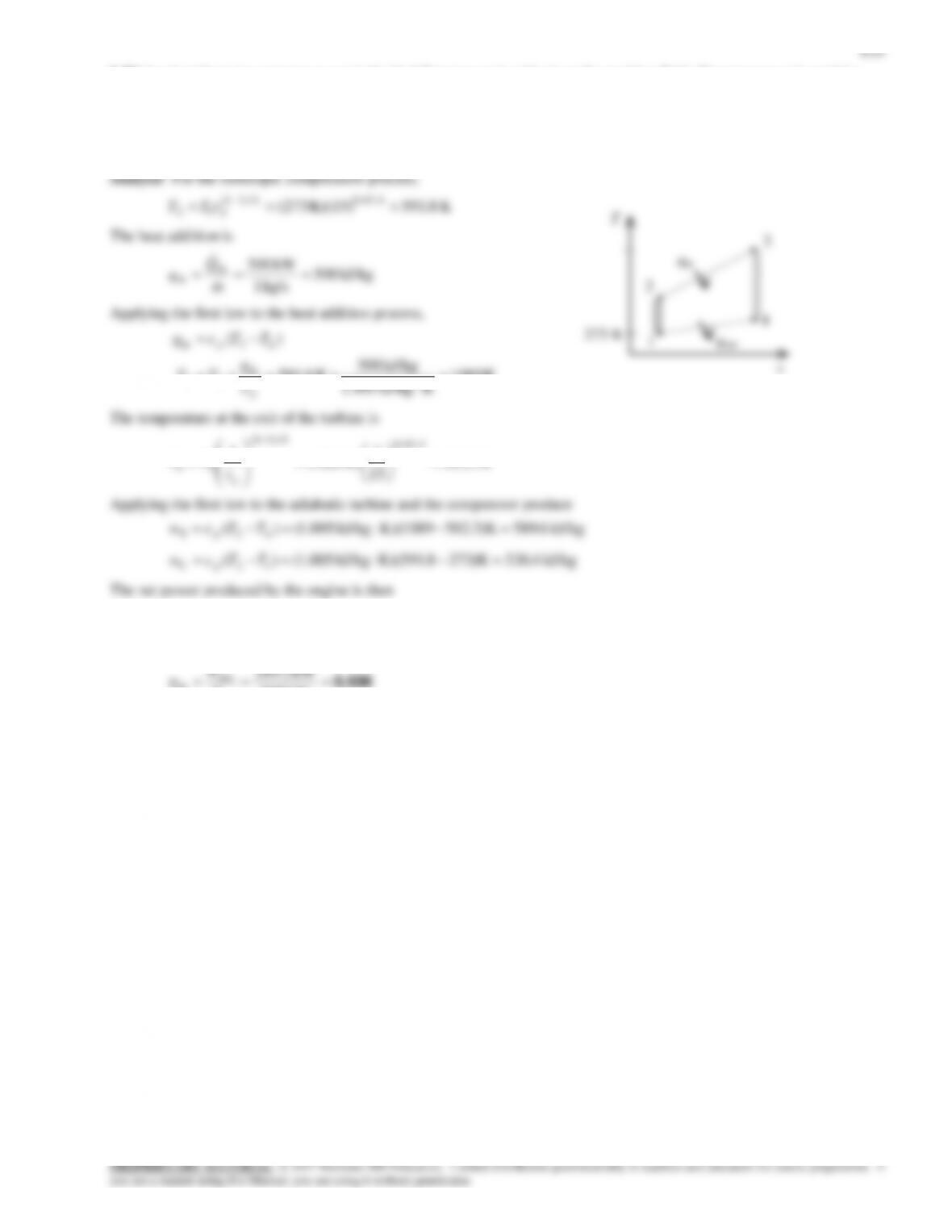
9-70 A simple Brayton cycle with air as the working fluid has a pressure ratio of 10. The air temperature at the turbine exit,
the net work output, and the thermal efficiency are to be determined.
9-54
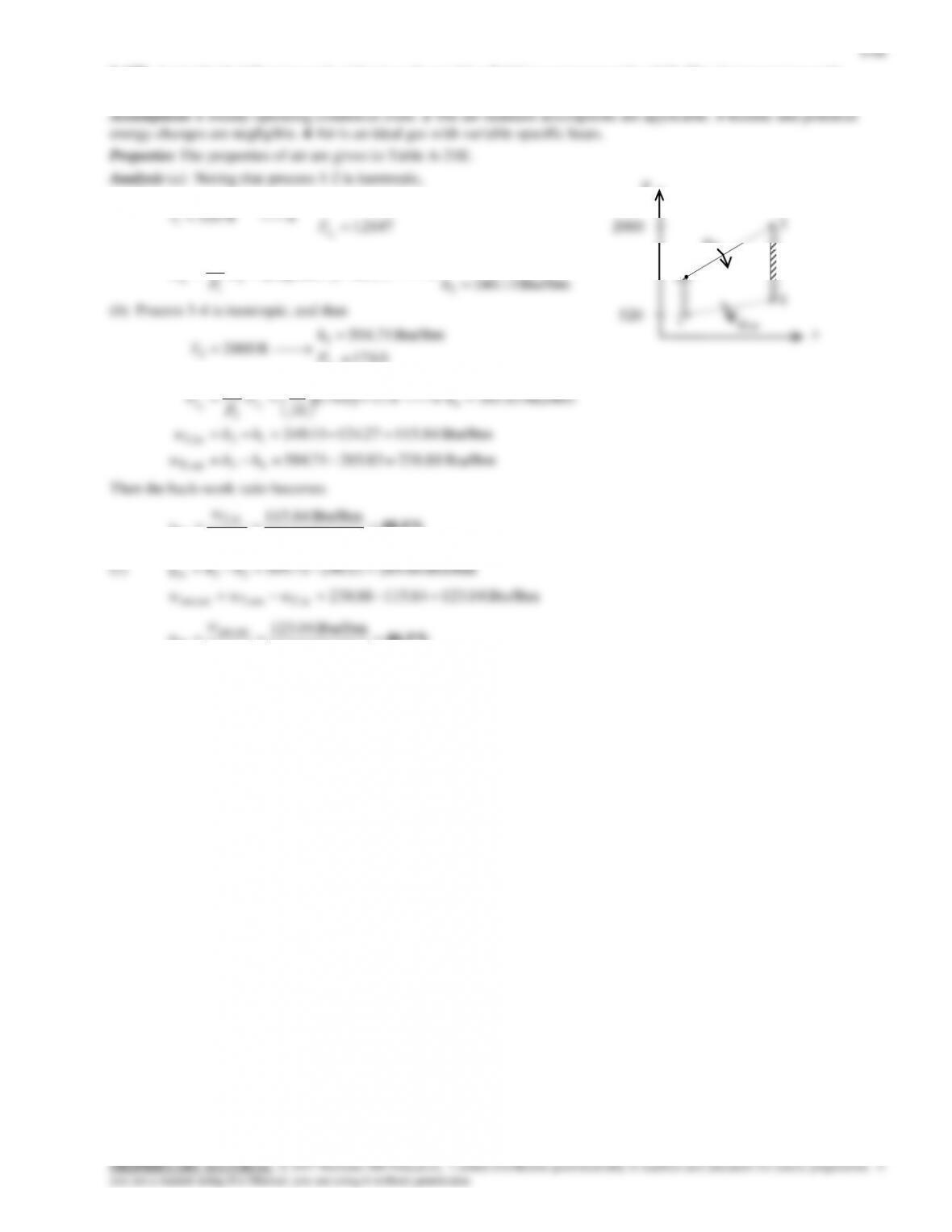
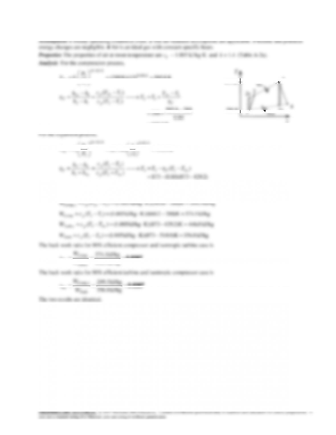
9-71 A simple Brayton cycle with air as the working fluid operates between the specified temperature and pressure limits.
The effects of non-isentropic compressor and turbine on the back-work ratio is to be compared.
K 8.585K)(12) 288( 0.4/1.4
/)1(
1
2
12
kk
sP
P
TT
K 2.660
80.0
2888.585
288
)(
)( 12
12
12
12
12
12
C
s
p
sp
s
C
TT
TT
TTc
TTc
hh
hh
For the expansion process,
K 2.429
12
1
K) 873(
0.4/1.4
/)1(
3
4
34
kk
sP
P
TT
K 0.518
)2.429873)(80.0(873
)(
)(
43
43
43
43
sp
p
s
TTc
TTc
hh
hh
The isentropic and actual work of compressor and turbine are
0.8387 kJ/kg 446.0
kJ/kg 374.1
Turb,
Comp
bw
s
W
W
r
4s
s
T
1
2s
4
3
qin
qout
873 K
288 K
2
9-55
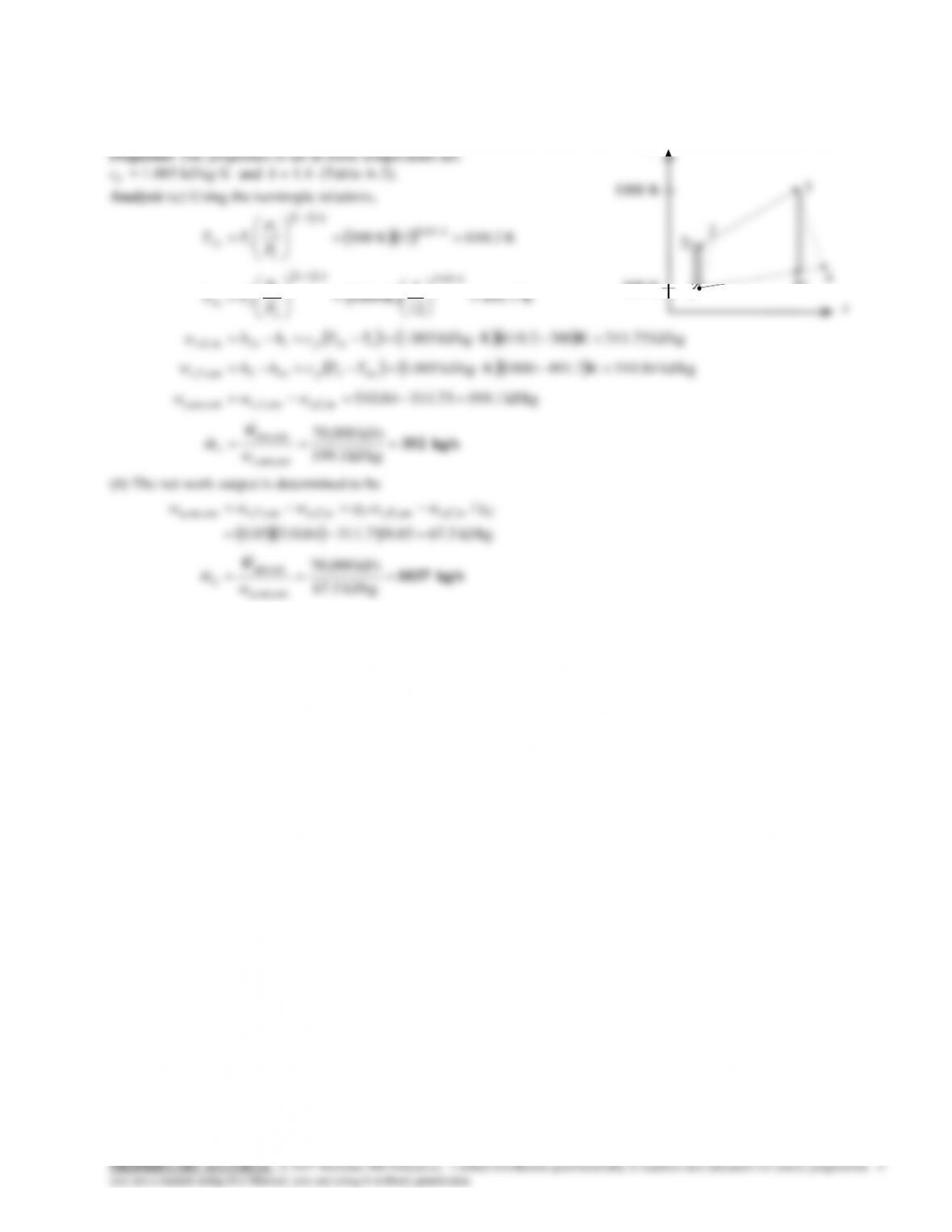
9-72 A gas turbine power plant that operates on the simple Brayton cycle with air as the working fluid has a specified
pressure ratio. The required mass flow rate of air is to be determined for two cases.
Assumptions 1 Steady operating conditions exist. 2 The air-standard assumptions are applicable. 3 Kinetic and potential
energy changes are negligible. 4 Air is an ideal gas with constant specific heats.
T
9-59
“GIVEN”
P_1=100 [kPa]
P_2=1600 [kPa]
T_1=40 [C]
s_1=entropy(Fluid$, T=T_1, P=P_1)
h_2s=enthalpy(Fluid$, P=P_2, s=s_1)
h_2=h_1+(h_2s-h_1)/eta_C
h_4=enthalpy(Fluid$, T=T_4)
s_3=entropy(Fluid$, T=T_3, P=P_2)