
9-1
Solutions Manual
for
Fundamentals of Thermal Fluid Sciences
5th Edition
Yunus A. Çengel, John M. Cimbala, Robert H. Turner
McGraw-Hill, 2017
Chapter 9
POWER AND REFRIGERATION CYCLES
PROPRIETARY AND CONFIDENTIAL
This Manual is the proprietary property of McGraw-Hill Education and protected by copyright and
other state and federal laws. By opening and using this Manual the user agrees to the following
restrictions, and if the recipient does not agree to these restrictions, the Manual should be promptly
returned unopened to McGraw-Hill Education: This Manual is being provided only to authorized
professors and instructors for use in preparing for the classes using the affiliated textbook. No
other use or distribution of this Manual is permitted. This Manual may not be sold and may not
be distributed to or used by any student or other third party. No part of this Manual may be
reproduced, displayed or distributed in any form or by any means, electronic or otherwise,
without the prior written permission of McGraw-Hill Education.
PROPRIETARY MATERIAL. © 2017 McGraw-Hill Education. Limited distribution permitted only to teachers and educators for course preparation. If
you are a student using this Manual, you are using it without permission.
9-1C The air standard assumptions are: (1) the working fluid is air which behaves as an ideal gas, (2) all the processes are
constant specific heats at room temperature.
same amount of net work as that produced during the actual cycle.
9-8C Assuming no accumulation of carbon deposits on the piston face, the compression ratio will remain the same
9-10C Stroke is the distance between the TDC and the BDC, bore is the diameter of the cylinder, TDC is the position of the
Analysis The maximum efficiency this cycle can have is
R )460(1100
R )460(80
H
L
T
T

9-5
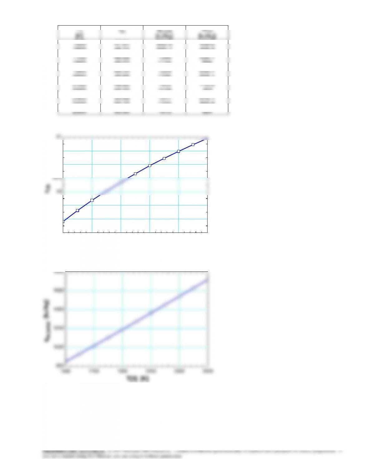
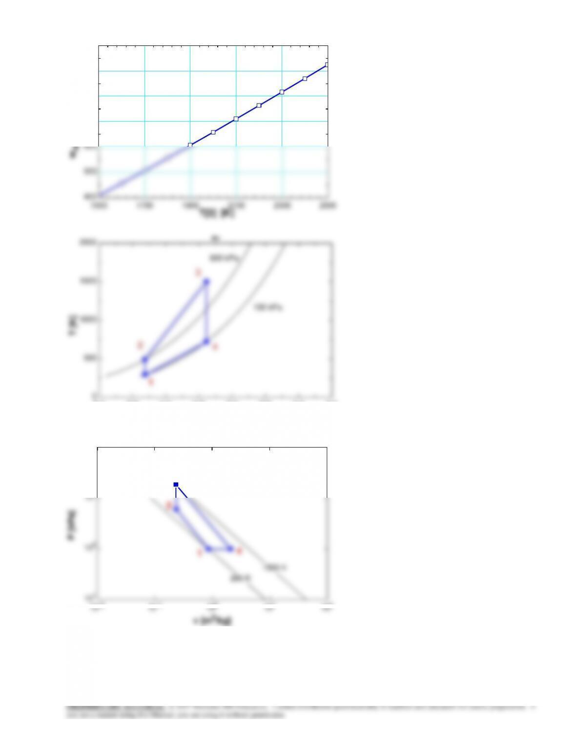
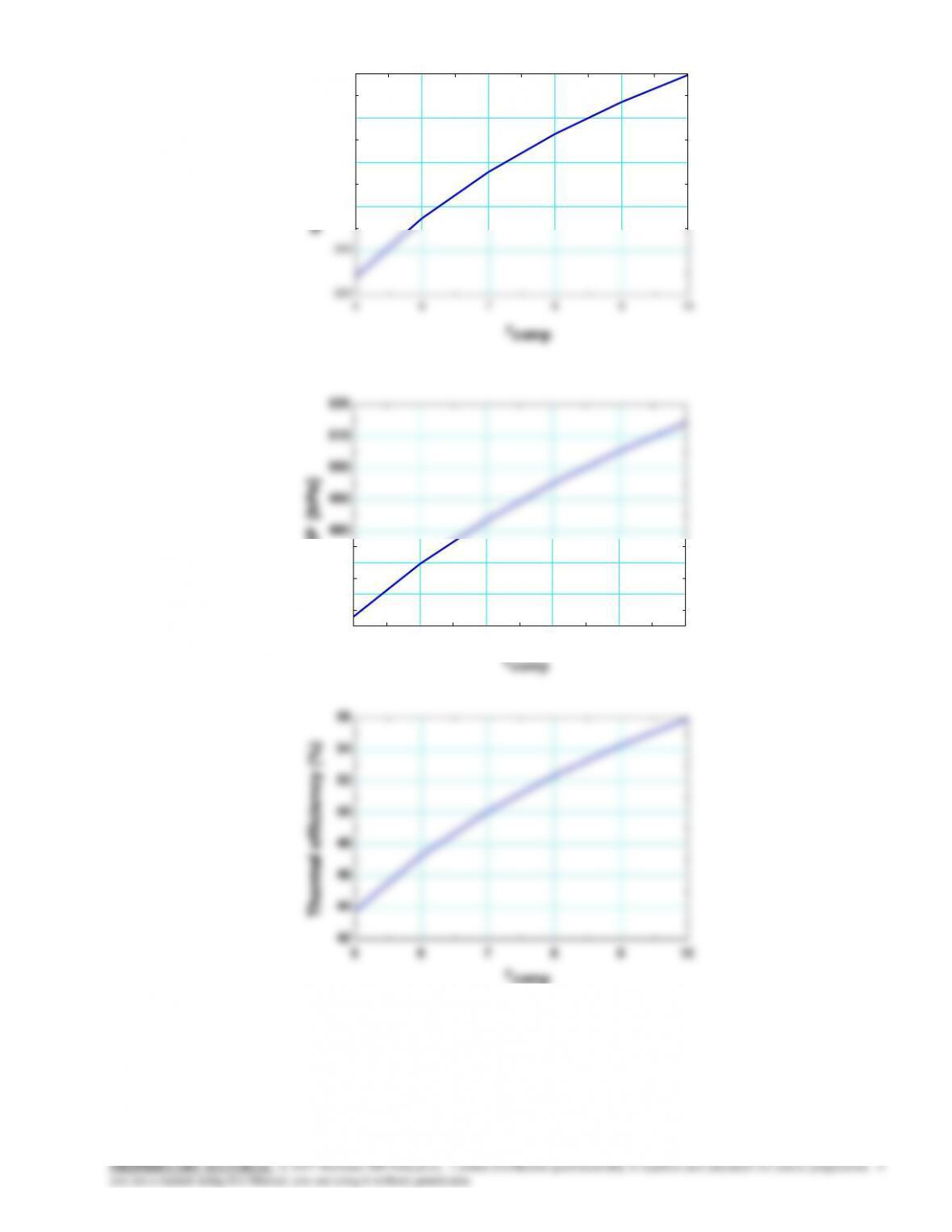
9-14 Problem 9-13 is reconsidered. The effect of the maximum temperature of the cycle on the net work output and
thermal efficiency is to be investigated. Also, T–s and P–
v
diagrams for the cycle are to be plotted.
Analysis Using EES, the problem is solved as follows:
“Input Data”
R=0.287 [kJ/kg-K]
“Conservation of energy for process 1 to 2″
q_12 -w_12 = DELTAu_12
q_12 =0“isentropic process”
DELTAu_12=intenergy(air,T=T[2])-intenergy(air,T=T[1])
s[4]=entropy(air,T=T[4],P=P[4])
s[4]=s[3]
P[4]*v[4]/T[4]=P[3]*v[3]/T[3]
{P[4]*v[4]=0.287*T[4]}
“Conservation of energy for process 3 to 4″
9-6
T3
[K]
th
qin,total
[kJ/kg]
Wnet
[kJ/kg]
1500
1600
1700
1800
1900
2000
2100
2200
2300
2400
2500
47.91
48.31
48.68
49.03
49.35
49.66
49.95
50.22
50.48
50.72
50.95
852.9
945.7
1040
1134
1229
1325
1422
1519
1617
1715
1813
408.6
456.9
506.1
556
606.7
658.1
710.5
763
816.1
869.8
924
1500 1700 1900 2100 2300 2500
47.5
48
48.5
49
49.5
50
50.5
51
T[3] [K]
th
1500 1700 1900 2100 2300 2500
800
1020
1240
1460
1680
1900
qin,total [kJ/kg]
9-7
1500 1700 1900 2100 2300 2500
400
500
600
700
800
900
1000
T[3] [K]
wnet [kJ/kg]
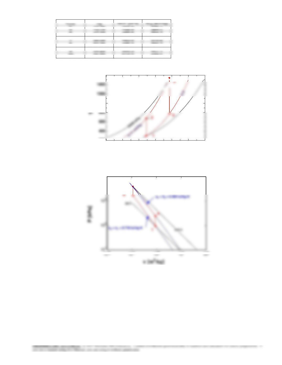
5.0 5.5 6.0 6.5 7.0 7.5 8.0 8.5
0
500
1000
1500
2000
s [kJ/kg-K]
T [K]
100 kPa
600 kPa
Air
1
2
3
4
10-2 10-1 100101102
101
102
103
104
P [kPa]
295 K
1500 K
Air
1
2
3
4
9-8
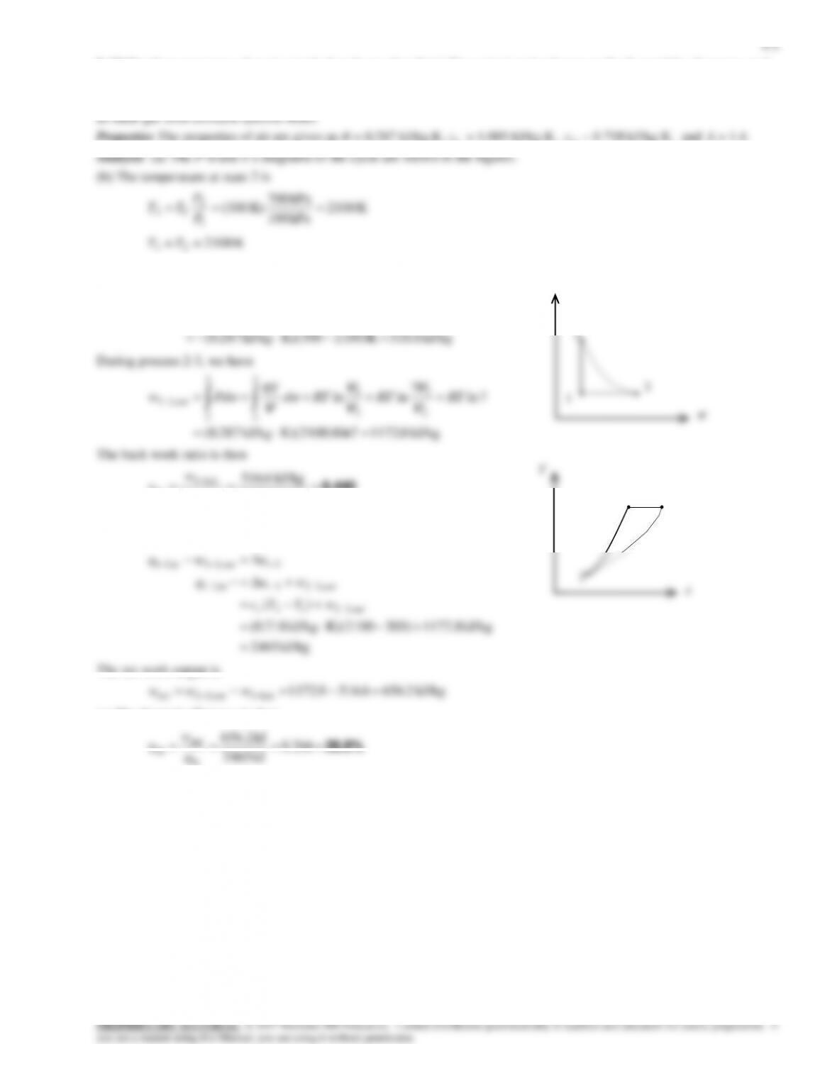
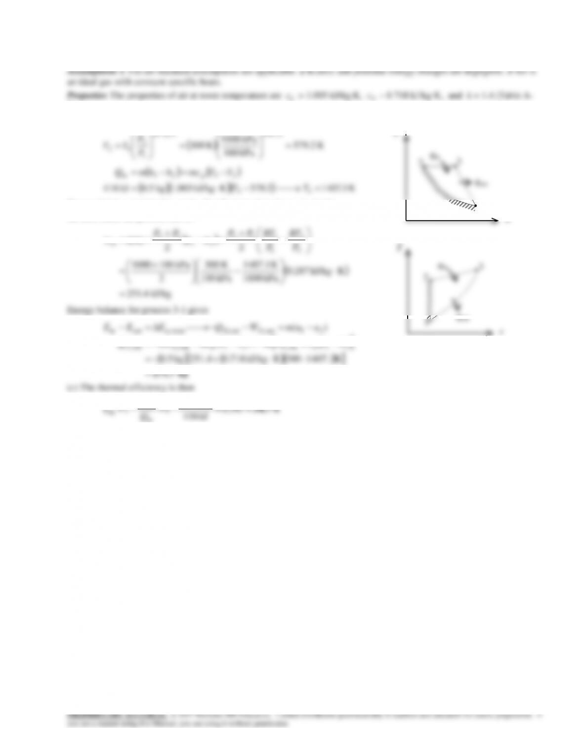
9-15 The three processes of an air-standard cycle are described. The cycle is to be shown on P-v and T-s diagrams, and the
heat rejected and the thermal efficiency are to be determined.
2).
Analysis (b) The temperature at state 2 and the heat input are
K 579.2
kPa 100
kPa 1000
K 300
0.4/1.4
/1
1
2
12
kk
P
P
TT
K 1.14072.579KkJ/kg 1.005kg 0.5kJ 416 33
2323in
TT
TTmchhmQ p
Process 3-1 is a straight line on the P–
v
diagram, thus the w31 is simply
the area under the process curve,
2
K 1407.1
K 300
kPa 1001000
22
area
3
3
1
1
13
31
13
31
P
RT
P
RT
PPPP
w
vv
kJ 271.7
K1407.1–300KkJ/kg 0.718251.4kg 0.5
)(
)(
31out31,31out31,out31,
31out31,out31,systemoutin
TTcwmTTmcmwQ
uumWQEEE
vv
(c) The thermal efficiency is then
34.7% 347.0
kJ 416
kJ 271.7
11
in
out
th
Q
Q
v
P
3
2
1
qin
qout
s
T
3
1
qout
qin
9-9
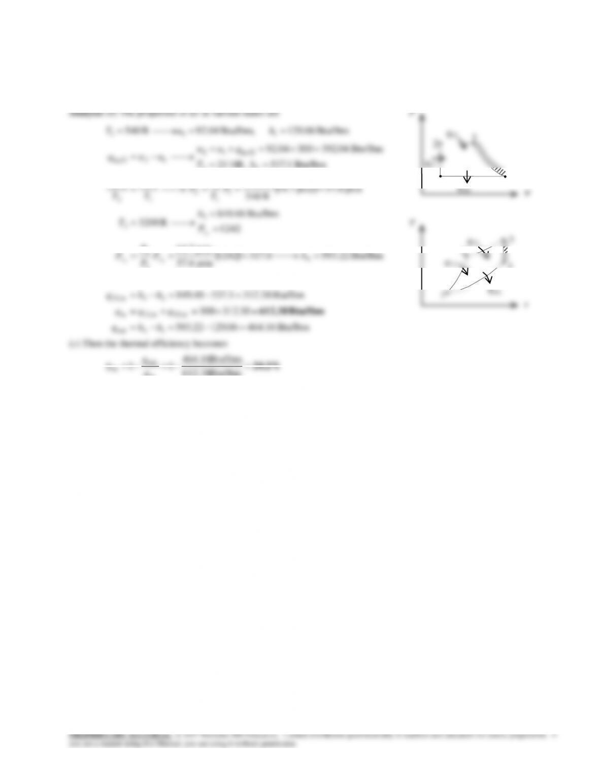
9-16E The four processes of an air-standard cycle are described. The cycle is to be shown on P-
v
and T-s diagrams, and the
total heat input and the thermal efficiency are to be determined.
Assumptions 1 The air-standard assumptions are applicable. 2 Kinetic and potential energy changes are negligible. 3 Air is
an ideal gas with variable specific heats.
Properties The properties of air are given in Table A-21E.
9-10
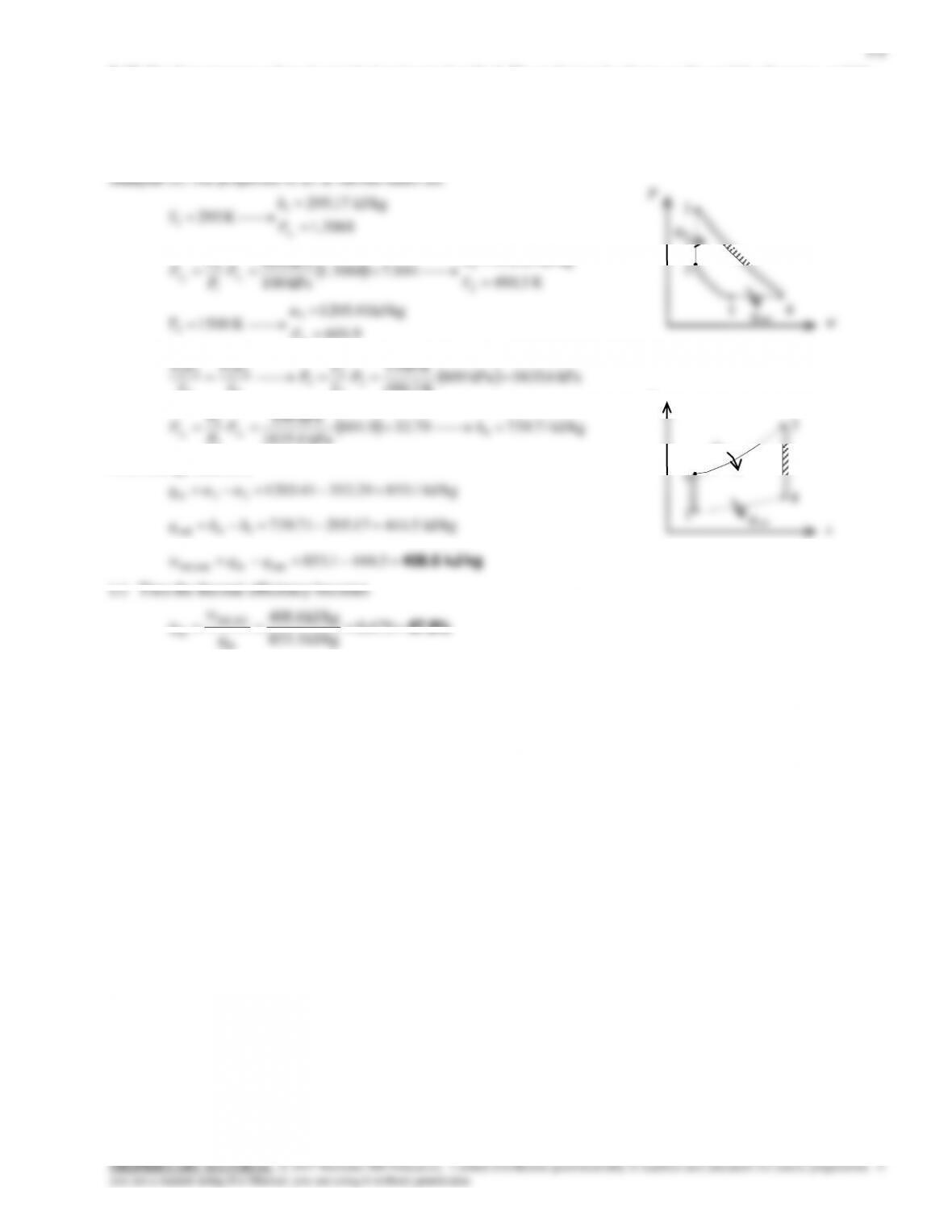
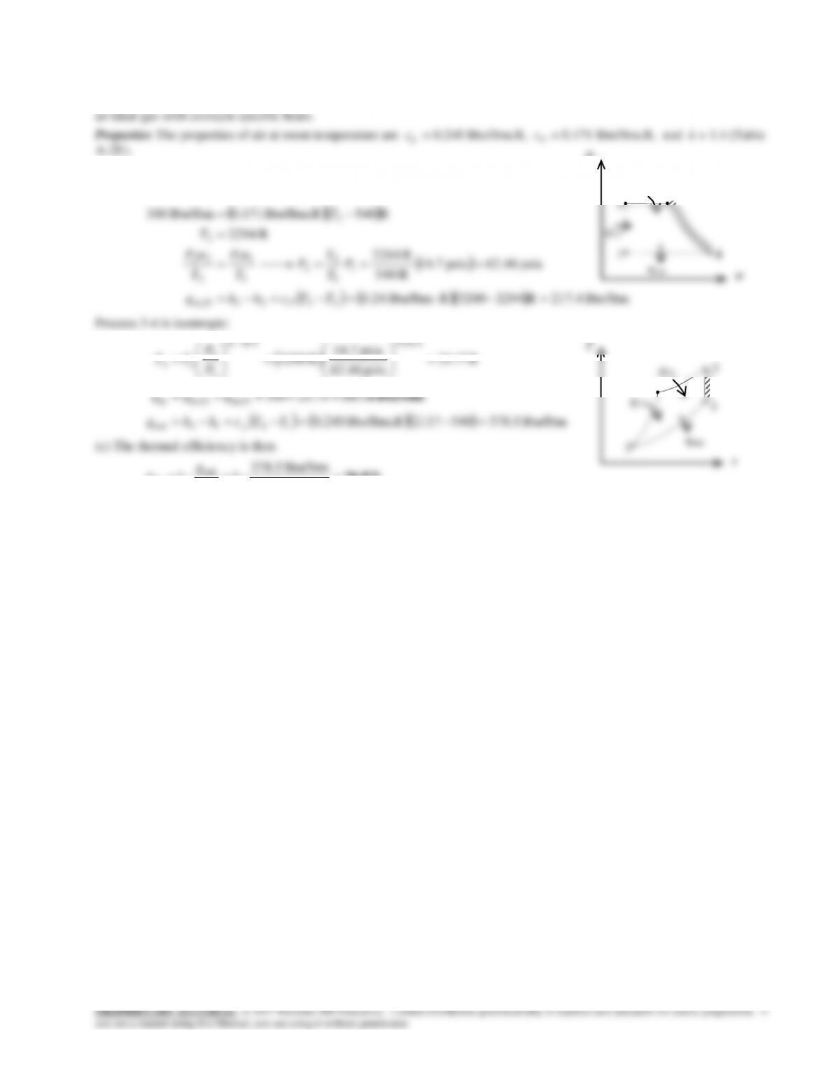
9-17E The four processes of an air-standard cycle are described. The cycle is to be shown on P-
v
and T-s diagrams, and the
total heat input and the thermal efficiency are to be determined.
Assumptions 1 The air-standard assumptions are applicable. 2 Kinetic and potential energy changes are negligible. 3 Air is
Analysis (b) The temperature at state 2 and the heat input are
R540Btu/lbm.R 0.171Btu/lbm 300
2
1212in,12
T
TTcuuq
v
P
3
2
q23
9-12
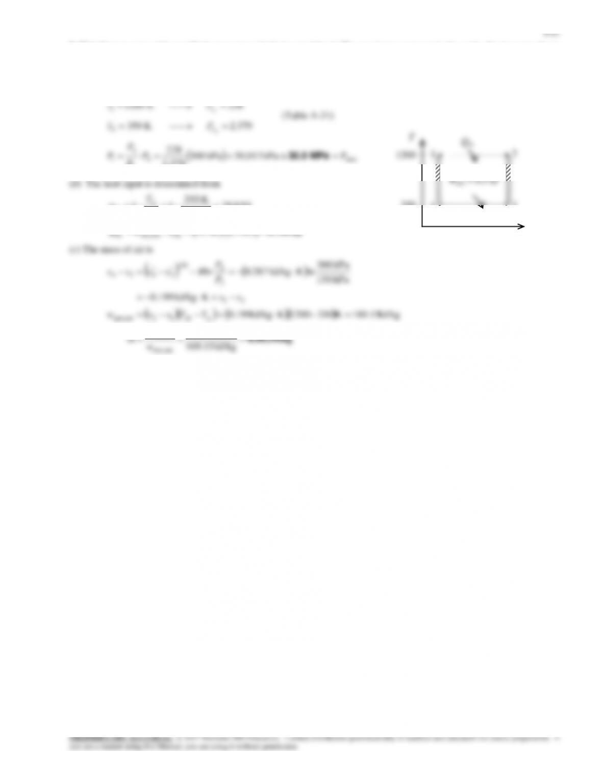
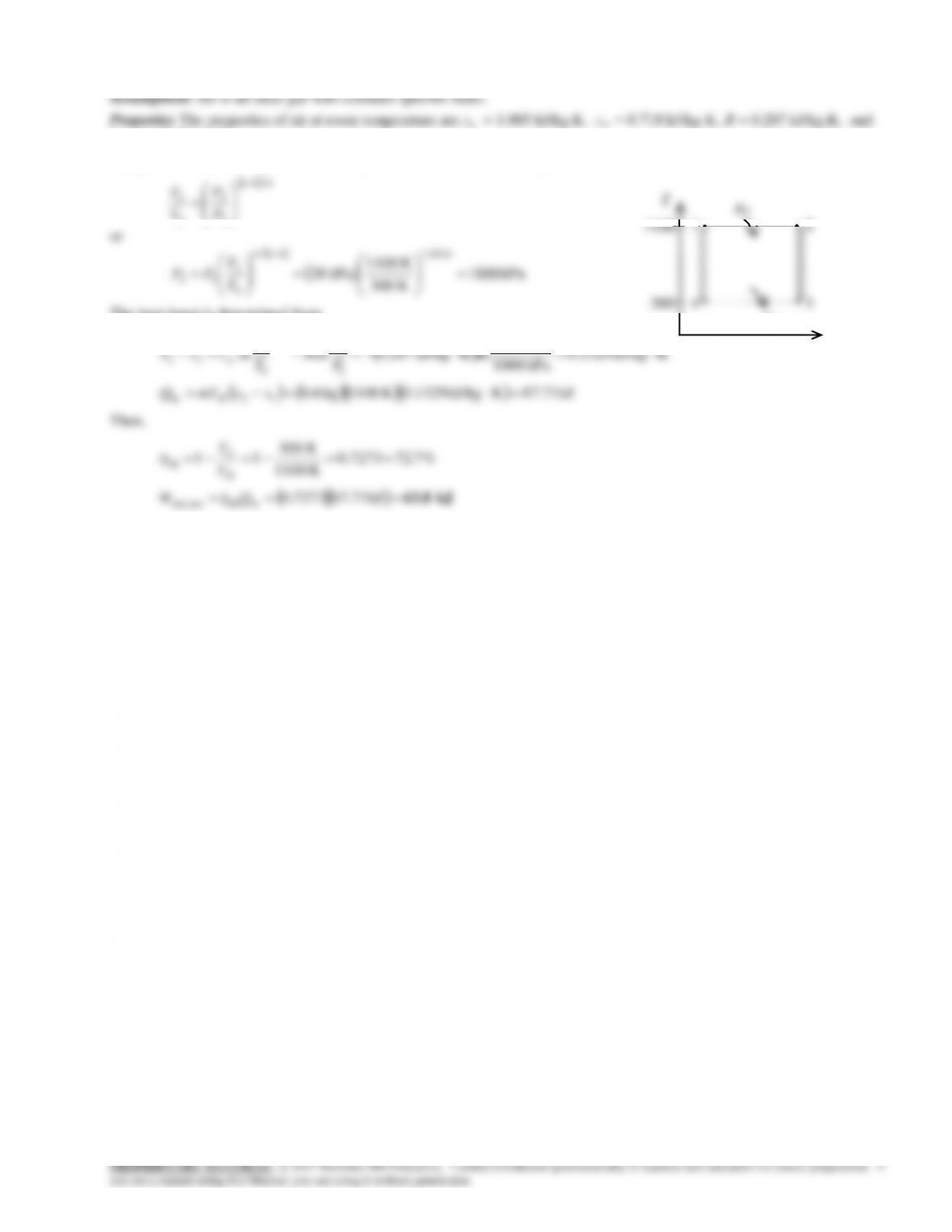
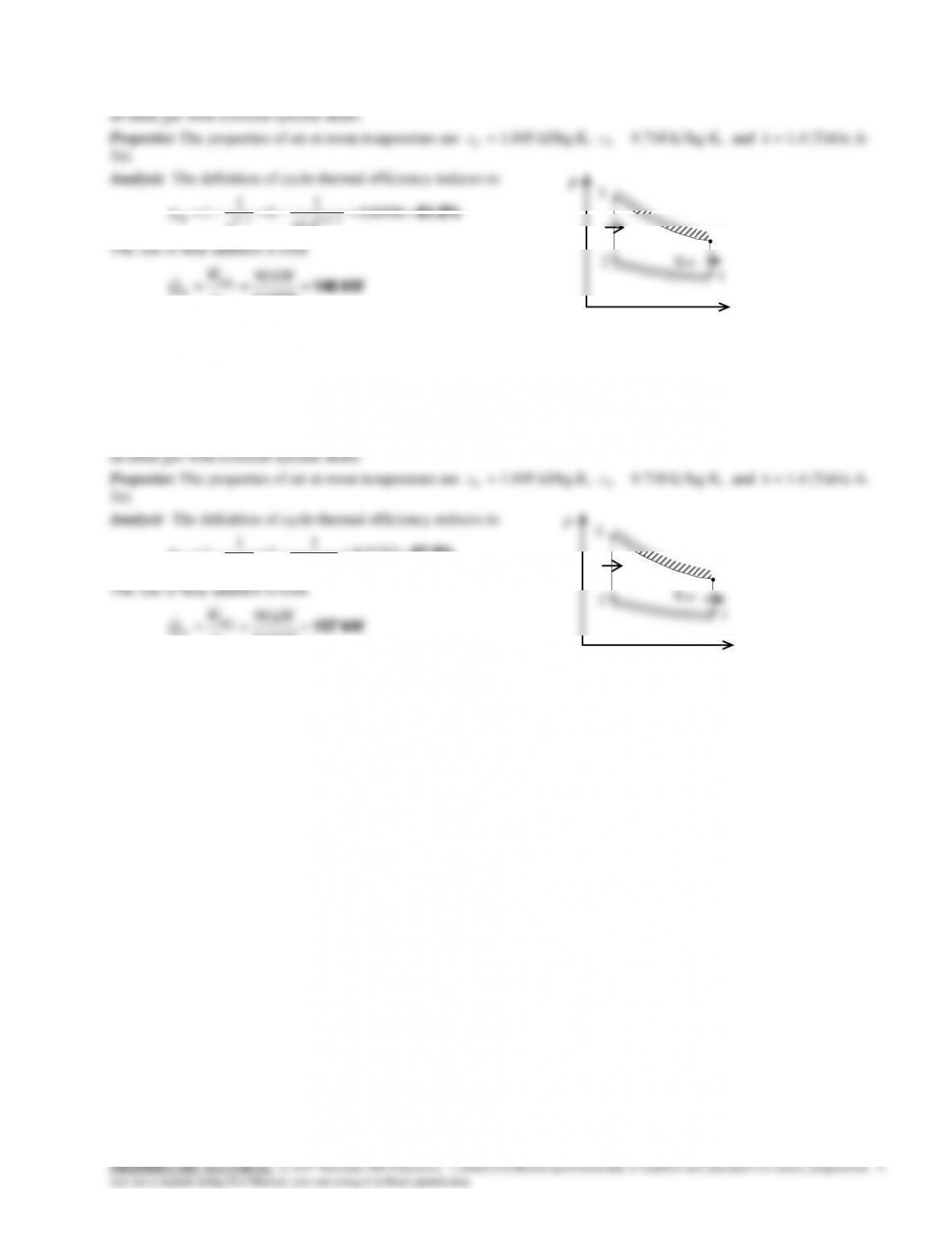
9-19 A Carnot cycle with specified temperature limits is considered. The maximum pressure in the cycle, the heat transfer
to the working fluid, and the mass of the working fluid are to be determined.
Assumptions Helium is an ideal gas with constant specific heats.
Properties The properties of helium at room temperature are R = 2.0769 kJ/kg.K and k = 1.667 (Table A-2).
Analysis (a) In a Carnot cycle, the maximum pressure occurs at the beginning of the expansion process, which is state 1.
/1
4
1
4
1
kk
P
P
T
T
kJ0.706 0.7083/kJ 0.5/
thoutnet,in
WQ
(c) The mass of helium is determined from
kg 0.000409
kJ/kg 1223.7
kJ 0.5
kJ/kg 1223.7K3501200KkJ/kg 1.4396
KkJ/kg 1.4396
kPa 150
kPa 300
lnKkJ/kg 2.0769lnln
outnet,
outnet,
12outnet,
21
3
4
0
3
4
34
w
W
m
TTssw
ss
P
P
R
T
T
css
LH
p
s
9-13
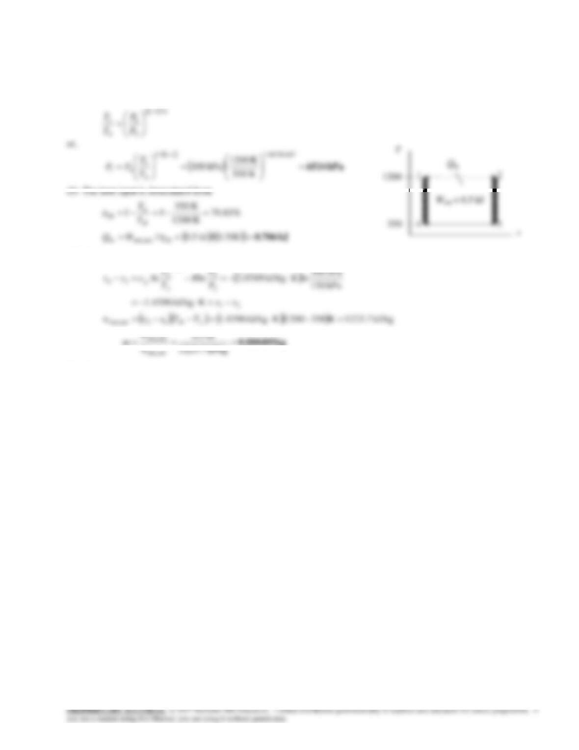
9-20 A Carnot cycle with the specified temperature limits is considered. The net work output per cycle is to be determined.
k = 1.4 (Table A-2).
Analysis The minimum pressure in the cycle is P3 and the maximum pressure is P1. Then,
/1
3
2
3
2
kk
P
P
T
T
T
2
qin
1
1100

PROPRIETARY MATERIAL. © 2017 McGraw-Hill Education. Limited distribution permitted only to teachers and educators for course preparation. If
you are a student using this Manual, you are using it without permission.
equal to the number of thermodynamic cycles.
9-27C The thermal efficiency will be the highest for argon because it has the highest specific heat ratio, k = 1.667.
9-15
9-29 An ideal Otto cycle is considered. The thermal efficiency and the rate of heat input are to be determined.
Assumptions 1 The air-standard assumptions are applicable. 2 Kinetic and potential energy changes are negligible. 3 Air is

9-17
9-32 Problem 9-31 is reconsidered. The effect of the compression ratio on the net work output and thermal efficiency
is to be investigated. Also, T–s and P–
v
diagrams for the cycle are to be plotted.
Analysis Using EES, the problem is solved as follows:
“Input Data”
R=0.287 [kJ/kg-K]
V[2] = V[1]/ r_comp
“Conservation of energy for process 1 to 2″
q_12 – w_12 = DELTAu_12
q_12 =0“isentropic process”
s[4]=s[3]
s[4]=entropy(air,T=T[4],P=P[4])
P[4]*v[4]=R*T[4]
“Conservation of energy for process 3 to 4″
q_34 -w_34 = DELTAu_34
9-18
rcomp
th
MEP [kPa]
wnet [kJ/kg]
5
43.78
452.9
328.4
6
47.29
469.6
354.7
7
50.08
483.5
375.6
8
52.36
495.2
392.7
9
54.28
505.3
407.1
10
55.93
514.2
419.5
4.5 5.0 5.5 6.0 6.5 7.0 7.5
200
400
600
800
1000
1200
1400
1600
s [kJ/kg–K]
T [K]
95 kPa
3900 kPa
0.9
0.11 m3/kg
Air
1
2
3
4
10-2 10-1 100101102
101
102
103
104
P [kPa]
300 K
1500 K
Air
1
2
3
4
s2 = s1 = 5.716 kJ/kg-K
s4 = 33 = 6.424 kJ/kg-K
9-19
5 6 7 8 9 10
320
340
360
380
400
420
rcomp
wnet [kJ/kg]
5 6 7 8 9 10
450
460
470
480
490
500
510
520
rcomp
MEP [kPa]
5 6 7 8 9 10
42
44
46
48
50
52
54
56
rcomp
Thermal efficiency (%)
9-20
9-33 An ideal Otto cycle with air as the working fluid has a compression ratio of 8. The pressure and temperature at the end
of the heat addition process, the net work output, the thermal efficiency, and the mean effective pressure for the cycle are to
be determined.
Assumptions 1 The air-standard assumptions are applicable. 2 Kinetic and potential energy changes are negligible. 3 Air is
an ideal gas with constant specific heats.
kPa 1745kPa 95
K 300
K 689
8
K 6898K300
1
1
2
2
1
2
1
11
2
22
0.4
1
2
1
12
P
T
T
P
T
P
T
P
TT
k
v
vvv
v
v
(c)
56.4% kJ/kg750
kJ/kg423
in
outnet,
th q
w
kPa534
kJ
mkPa
1/81/kgm 0.906
kJ/kg 423
)/11(
MEP
kPa 95
K 300K/kgmkPa 0.287
3
3
1
outnet,
21
outnet,
max
2min
max
3
3
1
1
1
r
ww
r
P
RT
vvv
v
vv
P
4
3
2
750 kJ/kg