8-61
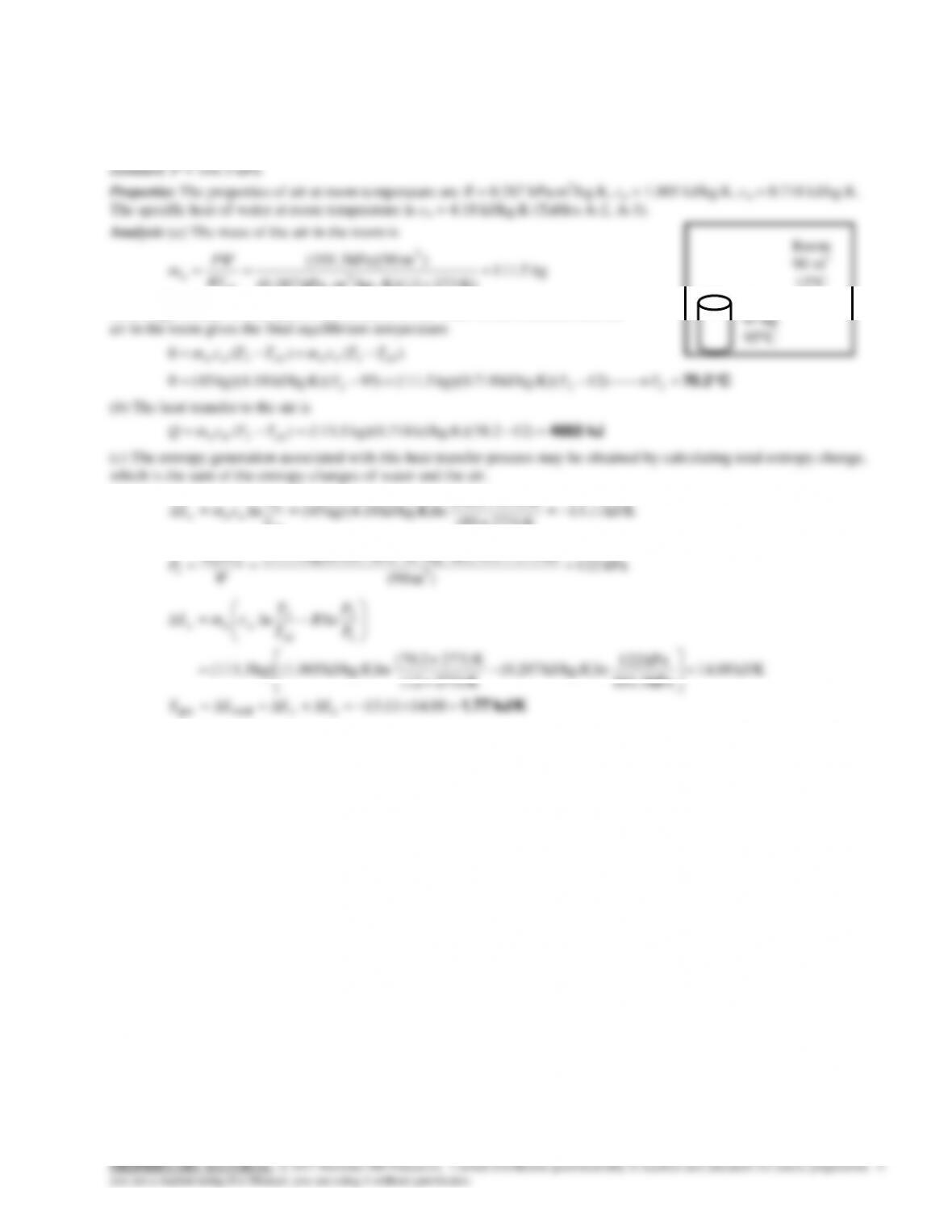
8-97 A container filled with liquid water is placed in a room and heat transfer takes place between the container and the air
in the room until the thermal equilibrium is established. The final temperature, the amount of heat transfer between the
water and the air, and the entropy generation are to be determined.
Assumptions 1 Kinetic and potential energy changes are negligible. 2 Air is an ideal gas with constant specific heats. 3 The
room is well-sealed and there is no heat transfer from the room to the surroundings. 4 Sea level atmospheric pressure is
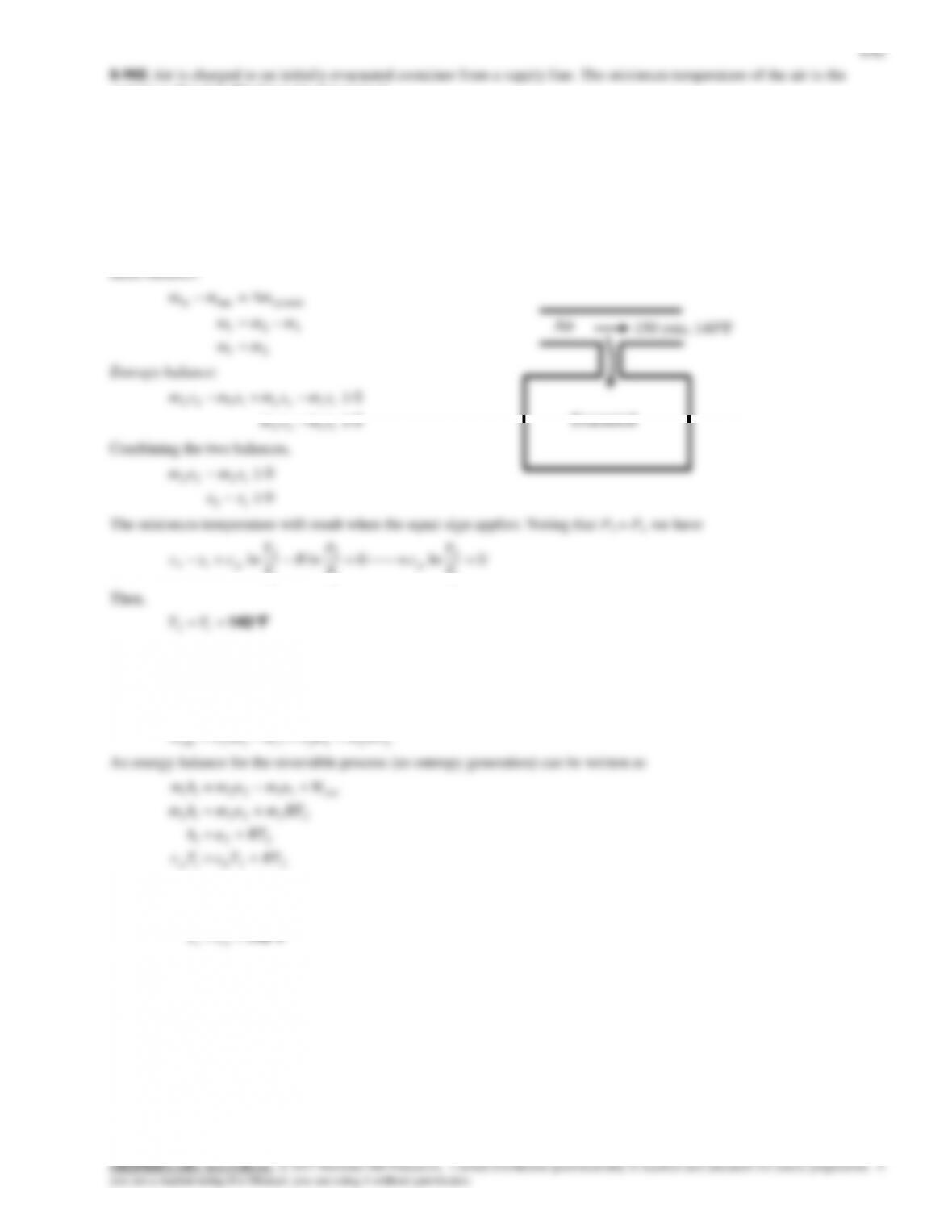
container after it is filled is to be determined.
Assumptions 1 This is an unsteady process since the conditions within the device are changing during the process, but it can
be analyzed as a uniform-flow process since the state of fluid at the inlet remains constant. 2 Air is an ideal gas with
constant specific heats. 3 Kinetic and potential energies are negligible. 4 The tank is well-insulated, and thus there is no heat
transfer.
Properties The specific heat of air at room temperature is cp = 0.240 Btu/lbm·R (Table A-2Ea).
Analysis We take the tank as the system, which is a control volume since mass crosses the boundary. Noting that the
microscopic energies of flowing and nonflowing fluids are represented by enthalpy h and internal energy u, respectively, the
mass and entropy balances for this uniform-flow system can be expressed as
8-63
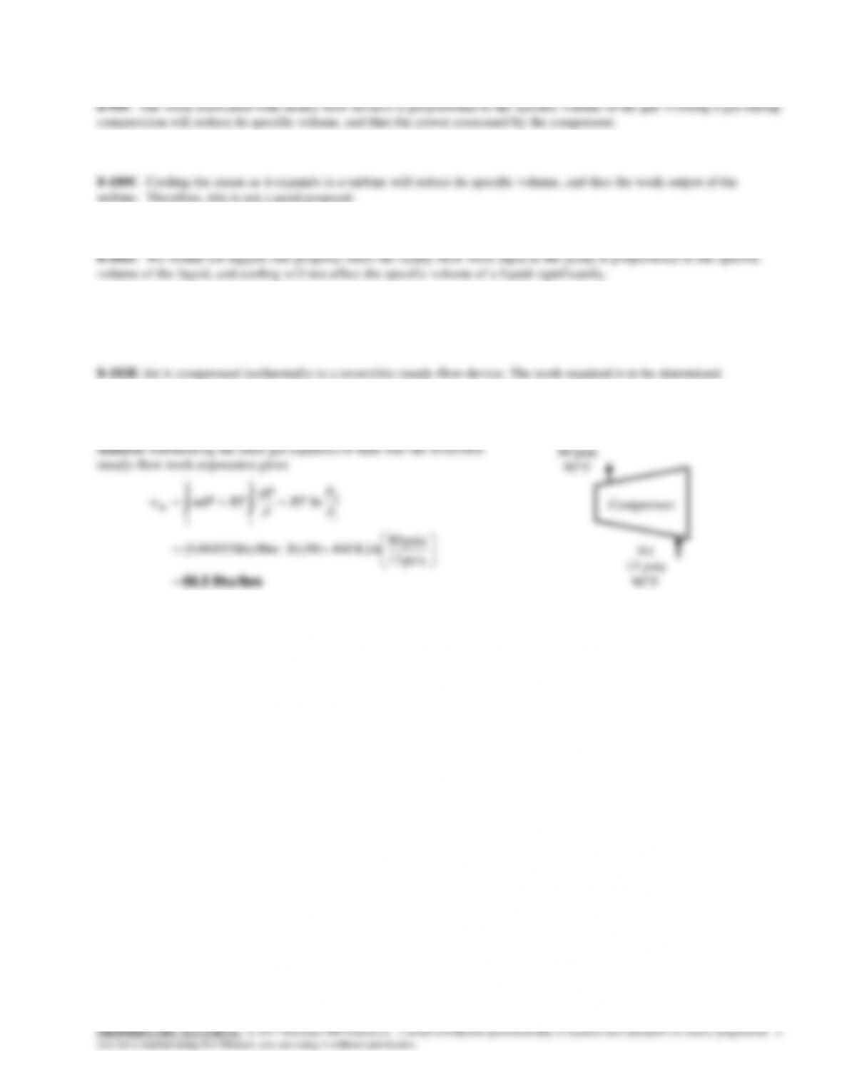
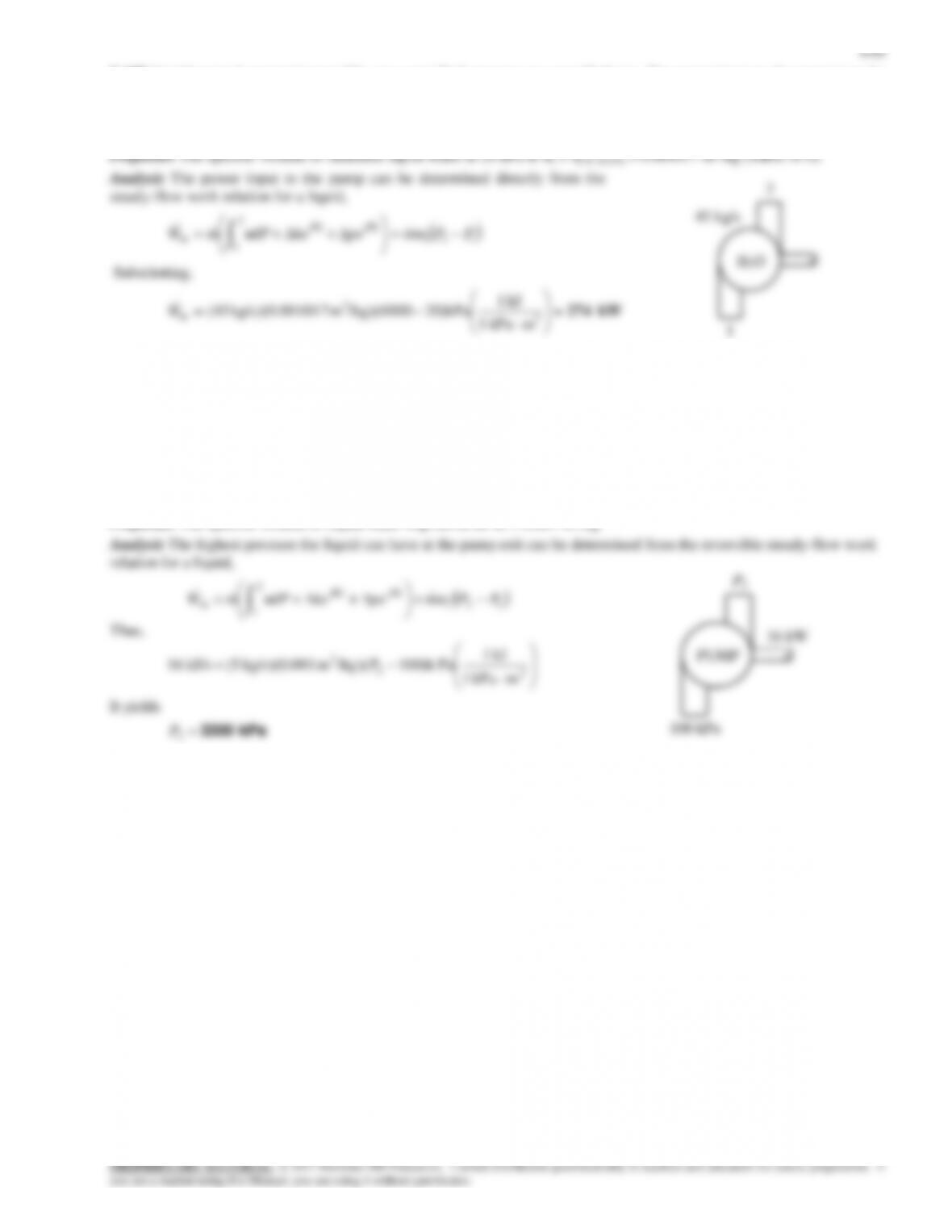
Reversible Steady-Flow Work
Assumptions 1 This is a steady-flow process since there is no change with time. 2 There is no heat transfer associated with
the process. 3 Kinetic and potential energy changes are negligible. 4 Air is an ideal gas with constant specific heats.
Properties The gas constant of air is R = 0.06855 Btu/lbm·R (Table A-1E).
Btu/lbm 68.5
psia 13
13 psia
90°F
8-64
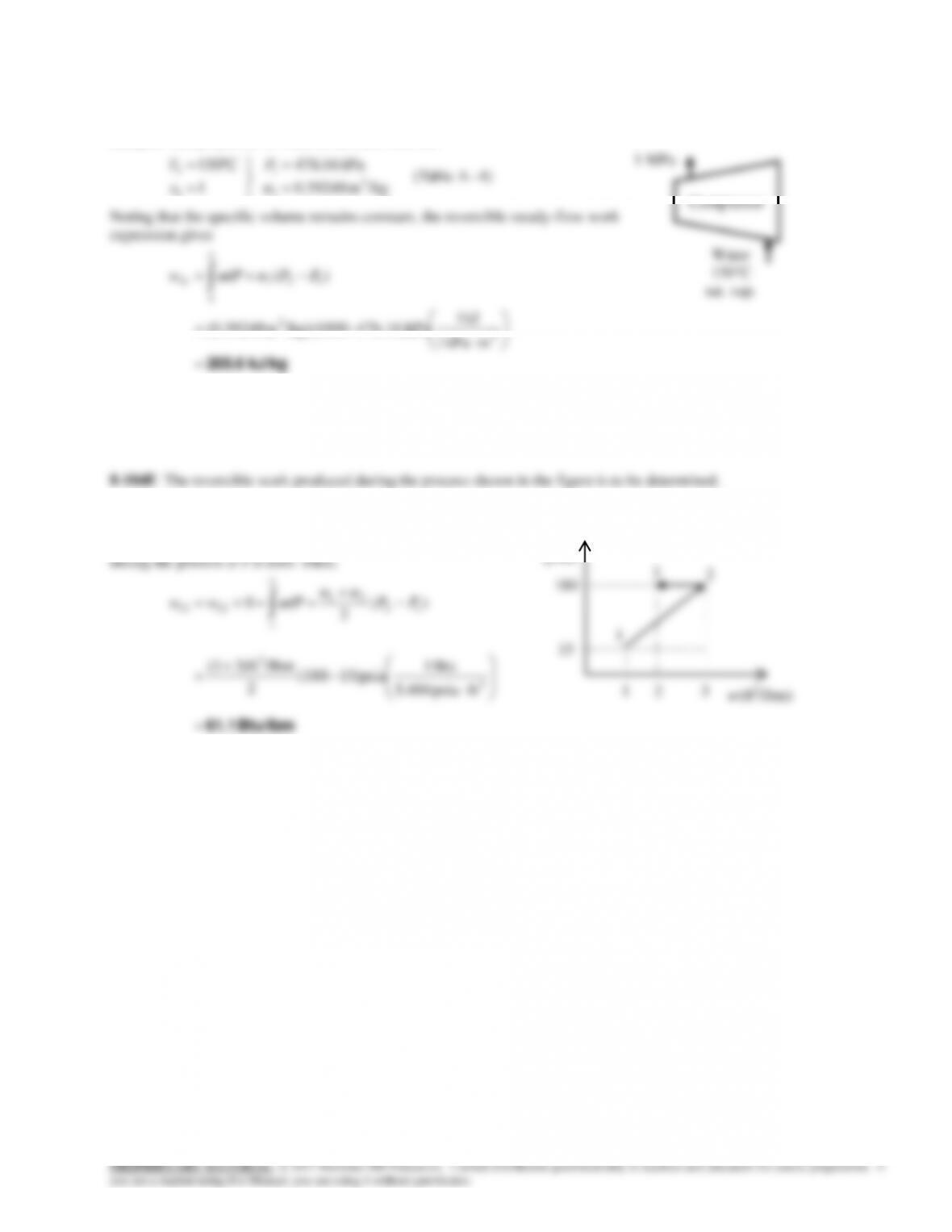
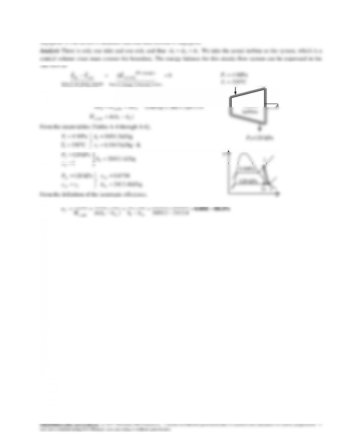
8-103 Saturated water vapor is compressed in a reversible steady-flow device. The work required is to be determined.
Assumptions 1 This is a steady-flow process since there is no change with time. 2 There is no heat transfer associated with
the process. 3 Kinetic and potential energy changes are negligible.
Analysis The properties of water at the inlet state are
4)–A (Table
/kgm 39248.0
kPa 16.476
1
C150
3
1
1
1
1
v
P
x
T
Noting that the specific volume remains constant, the reversible steady-flow work
expression gives
kJ/kg 205.6
3
3
121
2
1
in
mkPa 1
kJ 1
476.16)kPa–/kg)(1000m (0.39248
)( PPdPw
vv
Assumptions The process is reversible.
Analysis The work produced is equal to the areas to the left of
the reversible process line on the P-
v
diagram. The work done
Btu/lbm 61.1
3
ftpsia 404.5
2
Compressor
1 MPa
Water
150°C
sat. vap.
P
(psia)
1
3
2
v
(ft3/lbm)
8-66
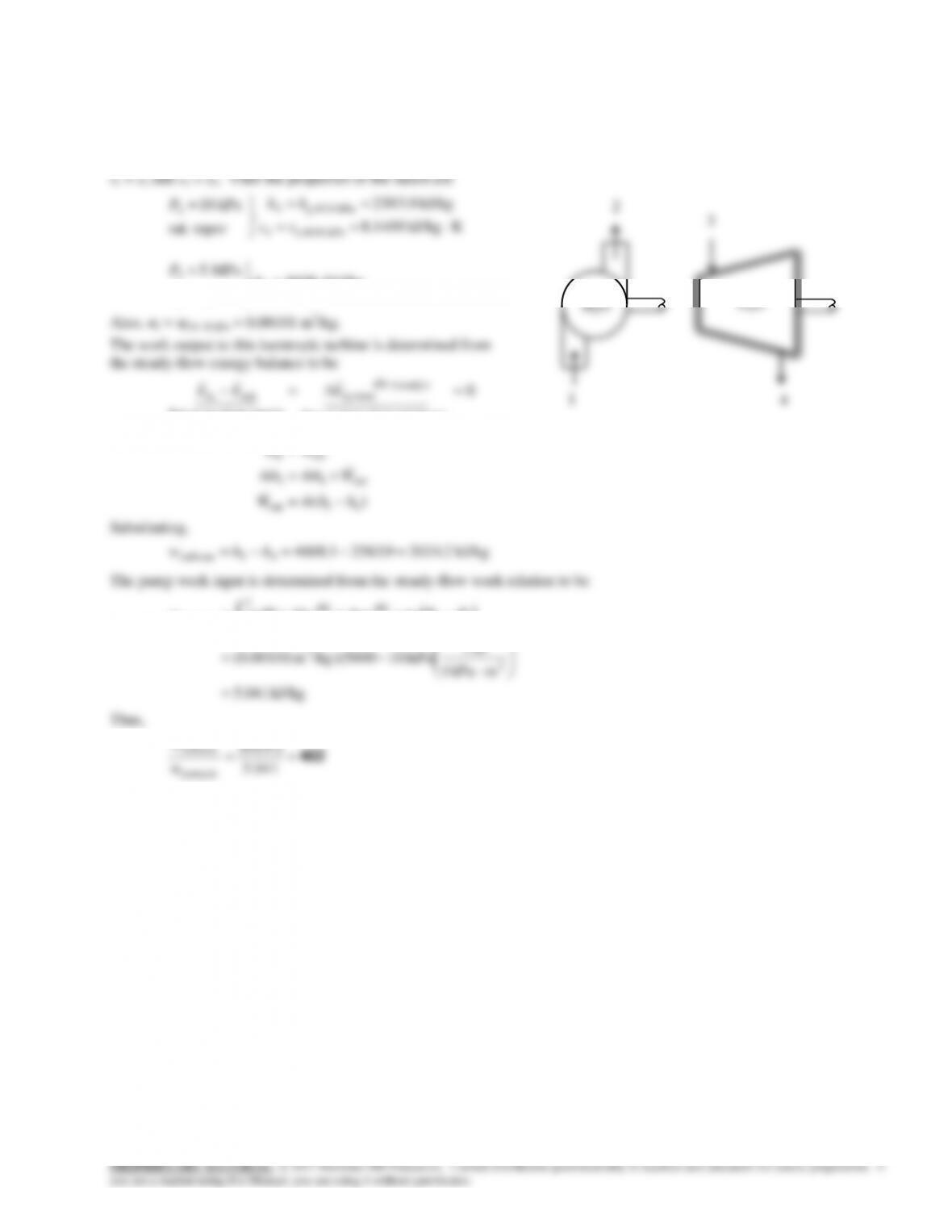
8-107 A steam power plant operates between the pressure limits of 5 MPa and 10 kPa. The ratio of the turbine work to the
pump work is to be determined.
Assumptions 1 Liquid water is an incompressible substance. 2 Kinetic and potential energy changes are negligible. 3 The
process is reversible. 4 The pump and the turbine are adiabatic.
Analysis Both the compression and expansion processes are reversible and adiabatic, and thus isentropic,
kJ/kg 4608.1
MPa 5
3
43
3
h
ss
P
Also,
v
1 =
v
f @ 10 kPa = 0.00101 m3/kg.
The work output to this isentropic turbine is determined from
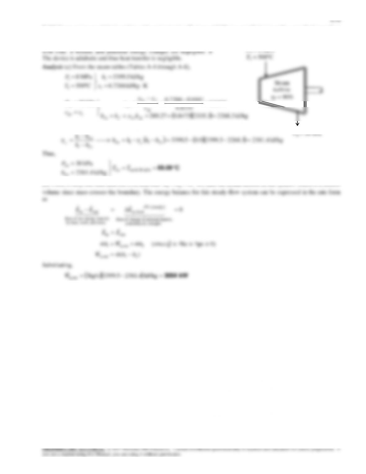
the steady-flow energy balance to be
)(
0
43out
out43
outin
energies etc. potential,
kinetic, internal,in change of Rate
(steady) 0
sy stem
mass and work,heat,by
nsferenergy tranet of Rate
outin
hhmW
Whmhm
EE
EEE
H2O
4
H2O
1
8-68
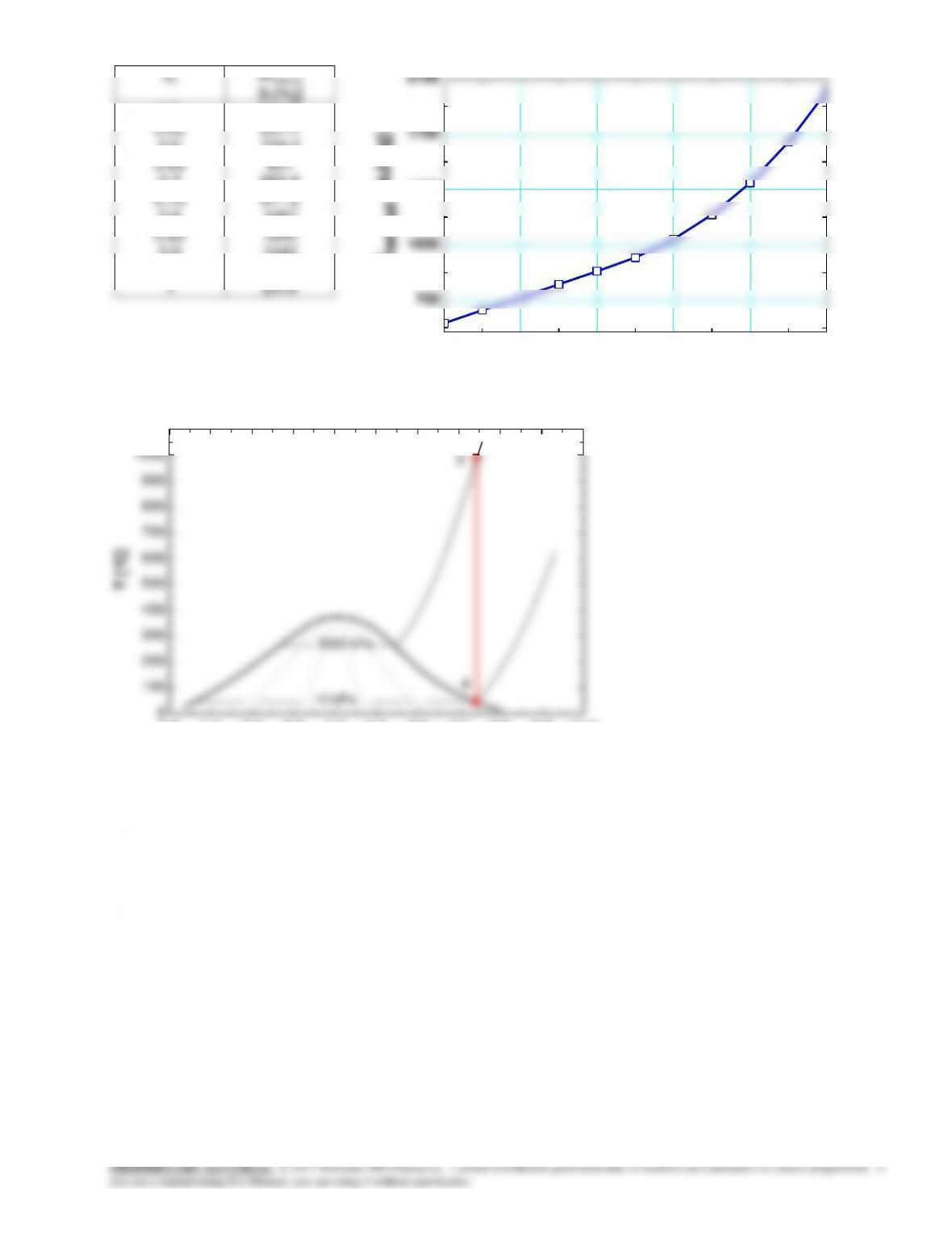
x4
Wnet,out
[kJ/kg]
0.5
0.55
0.6
0.65
0.7
0.75
0.8
0.85
0.9
0.95
1
555.6
637.4
719.2
801
882.8
971.2
1087
1240
1442
1699
2019
0.0 1.1 2.2 3.3 4.4 5.5 6.6 7.7 8.8 9.9 11.0
0
100
200
300
400
500
600
700
800
900
1000
1100
s [kJ/kg-K]
T [°C]
5000 kPa
10 kPa
0.2 0.4 0.6 0.8
Ste am IAPW S
3
4
0.5 0.6 0.7 0.8 0.9 1
700
1050
1400
1750
2100
x[4]
Wnet,out [kJ/kg]
PROPRIETARY MATERIAL. © 2017 McGraw-Hill Education. Limited distribution permitted only to teachers and educators for course preparation. If
you are a student using this Manual, you are using it without permission.
efficiencies of these devices are defined as
energy kineticexit cinsentropi
energykineticexit actual
inputwork actual
inputwork cinsentropi
outputwork cinsentropi
outputwork actual NCT
PROPRIETARY MATERIAL. © 2017 McGraw-Hill Education. Limited distribution permitted only to teachers and educators for course preparation. If
you are a student using this Manual, you are using it without permission.
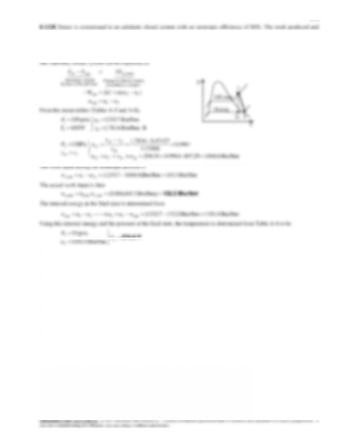
the final temperature are to be determined.
Assumptions 1 Kinetic and potential energy changes are negligible. 2 The device is adiabatic and thus heat transfer is
negligible.
Analysis We take the steam as the system. This is a closed system since no mass enters or leaves. The energy balance for
F274.6
2
2
2
Btu/lbm 4.1101
psia 10 T
u
P
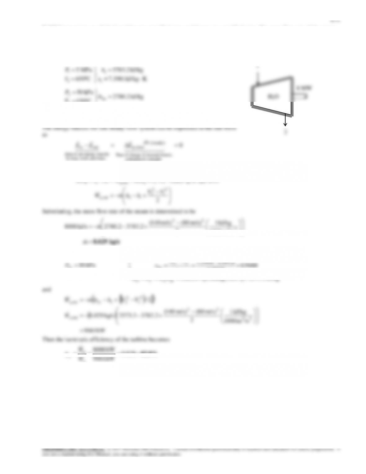
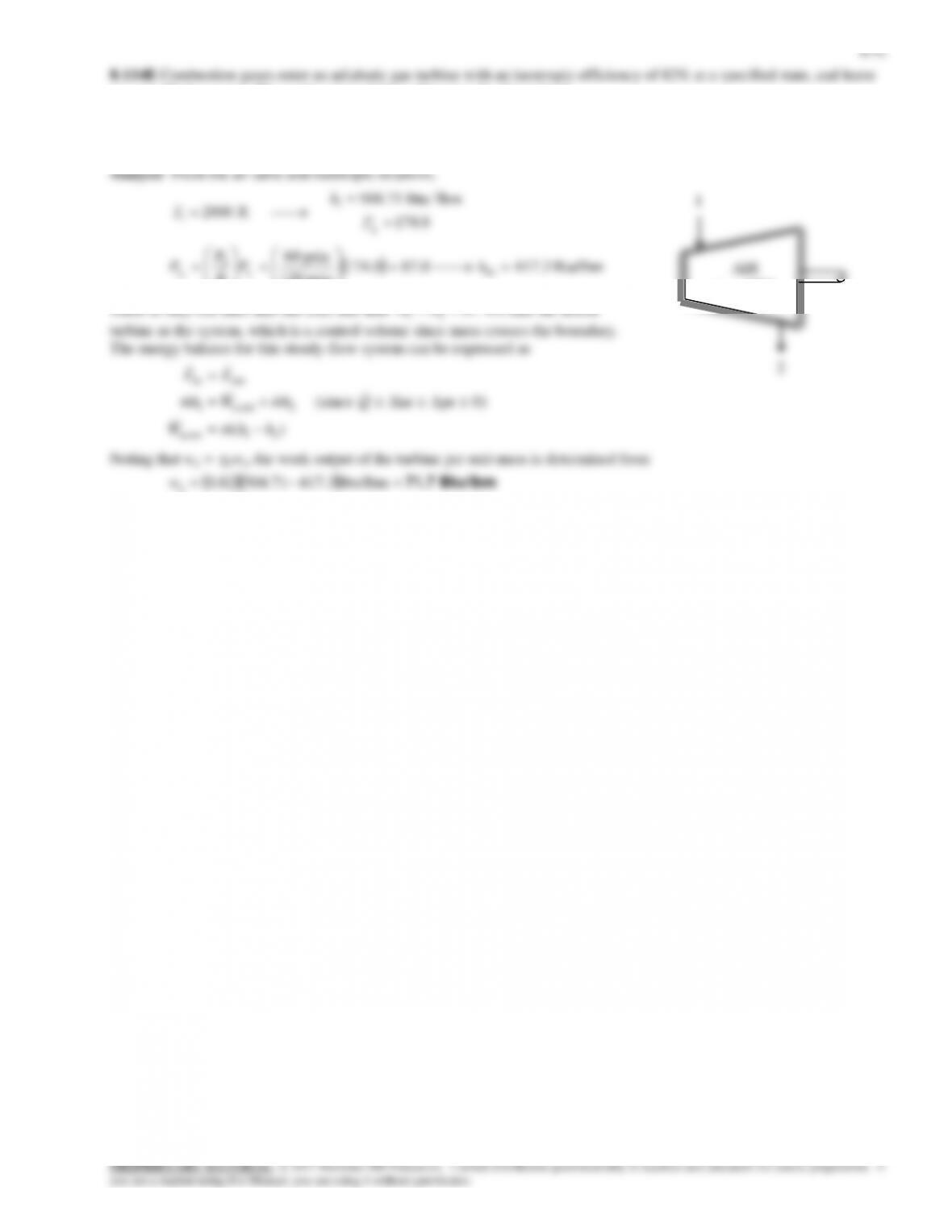
at a specified pressure. The work output of the turbine is to be determined.
Assumptions 1 This is a steady-flow process since there is no change with time. 2 Kinetic and potential energy changes are
negligible. 3 The device is adiabatic and thus heat transfer is negligible. 4 Combustion gases can be treated as air that is an
ideal gas with variable specific heats.
8-73
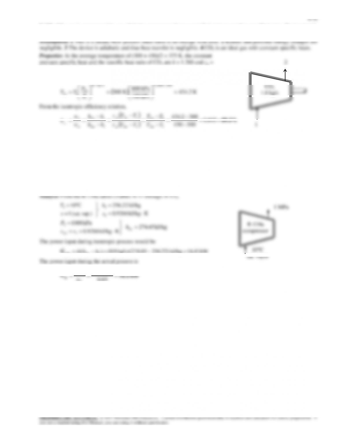
8-115 Steam is expanded in an adiabatic turbine. The isentropic efficiency is to be determined.
Assumptions 1 This is a steady-flow process since there is no change with time. 2 Kinetic and potential energy changes are
)(
0)ΔpeΔke (since
0
21out,
2out,1
outin
energies etc. potential,
kinetic, internal,in change of Rate
(steady) 0
sy stem
mass and work,heat,by
nsferenergy tranet of Rate
outin
hhmW
QhmWhm
EE
EEE
a
a
Steam
turbine
P1 = 4 MPa
T1 = 350C
8-75
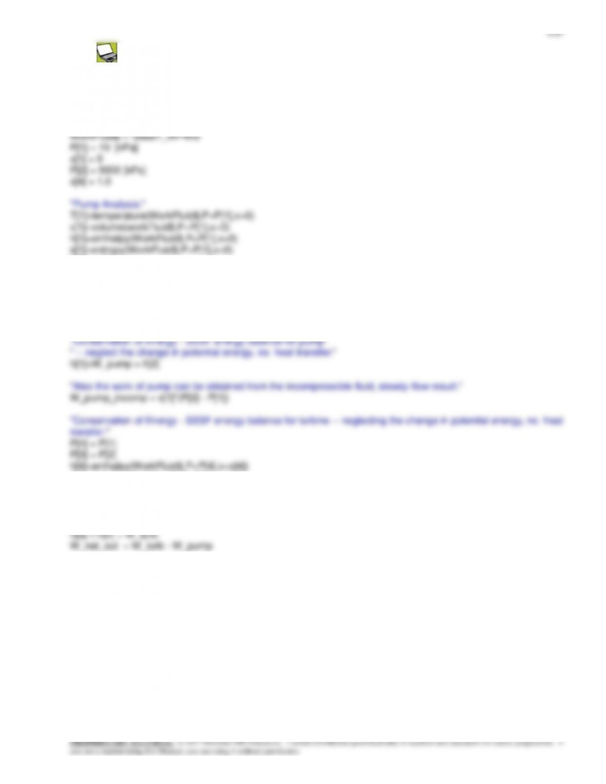
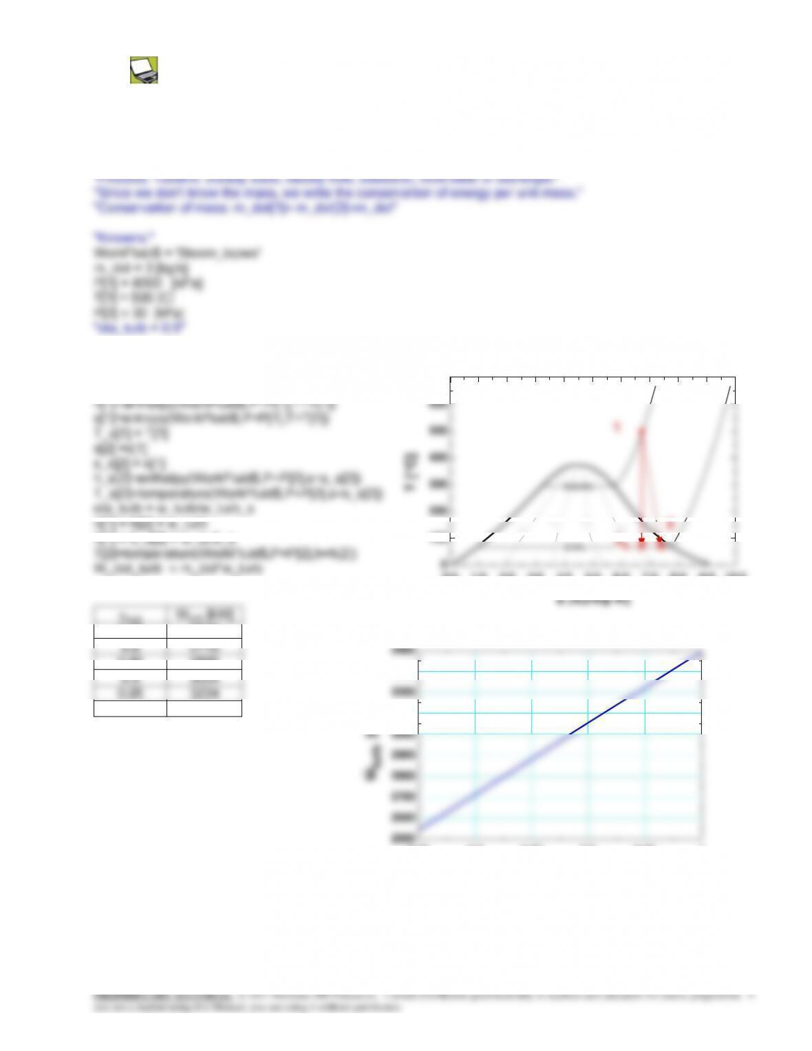
8-117 Problem 8-116 is reconsidered. The effect of varying the turbine isentropic efficiency from 0.75 to 1.0 on both
the work done and the exit temperature of the steam are to be investigated, and the results are to be plotted.
Analysis The problem is solved using EES, and the results are tabulated and plotted below.
“System: control volume for turbine”
“Property relation: Steam functions”
“Conservation of Energy – SSSF energy balance for
turbine — neglecting the change in potential energy,
no heat transfer:”
0.0 1.0 2.0 3.0 4.0 5.0 6.0 7.0 8.0 9.0 10.0
700
Steam
8-77
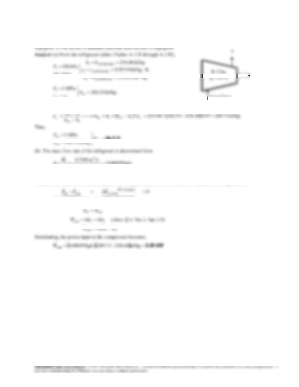
8-120 Refrigerant-134a enters an adiabatic compressor with an isentropic efficiency of 0.87 at a specified state with a
specified volume flow rate, and leaves at a specified pressure. The compressor exit temperature and power input to the
compressor are to be determined.
Assumptions 1 This is a steady-flow process since there is no change with time. 2 Kinetic and potential energy changes are

8-79
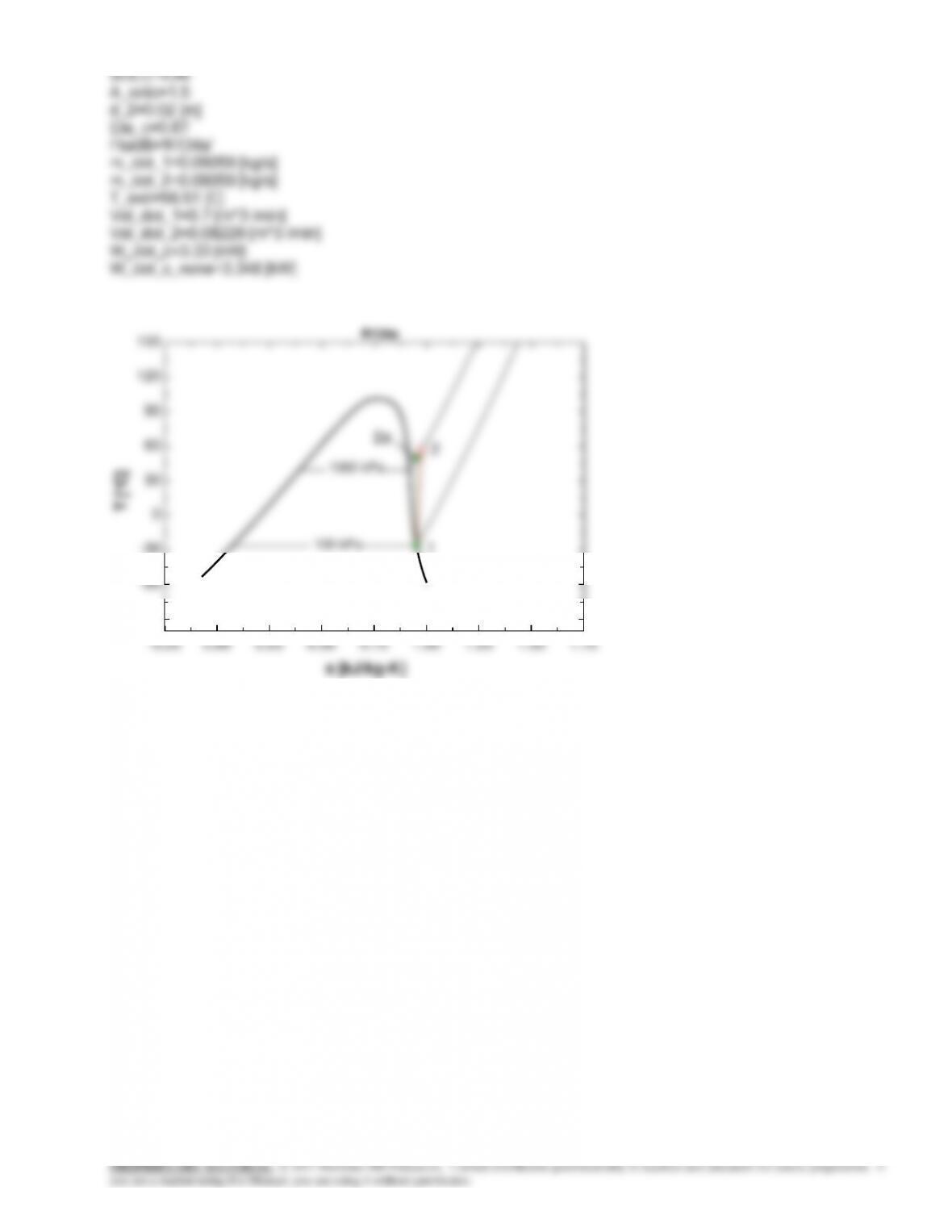
SOLUTION
A_ratio=1.5
d_2=0.02 [m]
Eta_c=0.87
Fluid$=’R134a’
m_dot_1=0.06059 [kg/s]
m_dot_2=0.06059 [kg/s]
T_exit=56.51 [C]
Vol_dot_1=0.7 [m^3 /min]
Vol_dot_2=0.08229 [m^3 /min]
W_dot_c=3.33 [kW]
W_dot_c_noke=3.348 [kW]
–0.25 0.00 0.25 0.50 0.75 1.00 1.25 1.50 1.75
–90
–60
–30
0
30
60
90
120
150
s [kJ/kg-K]
T [°C]
1000 kPa
100 kPa
R134a
1
2
2s
8-80
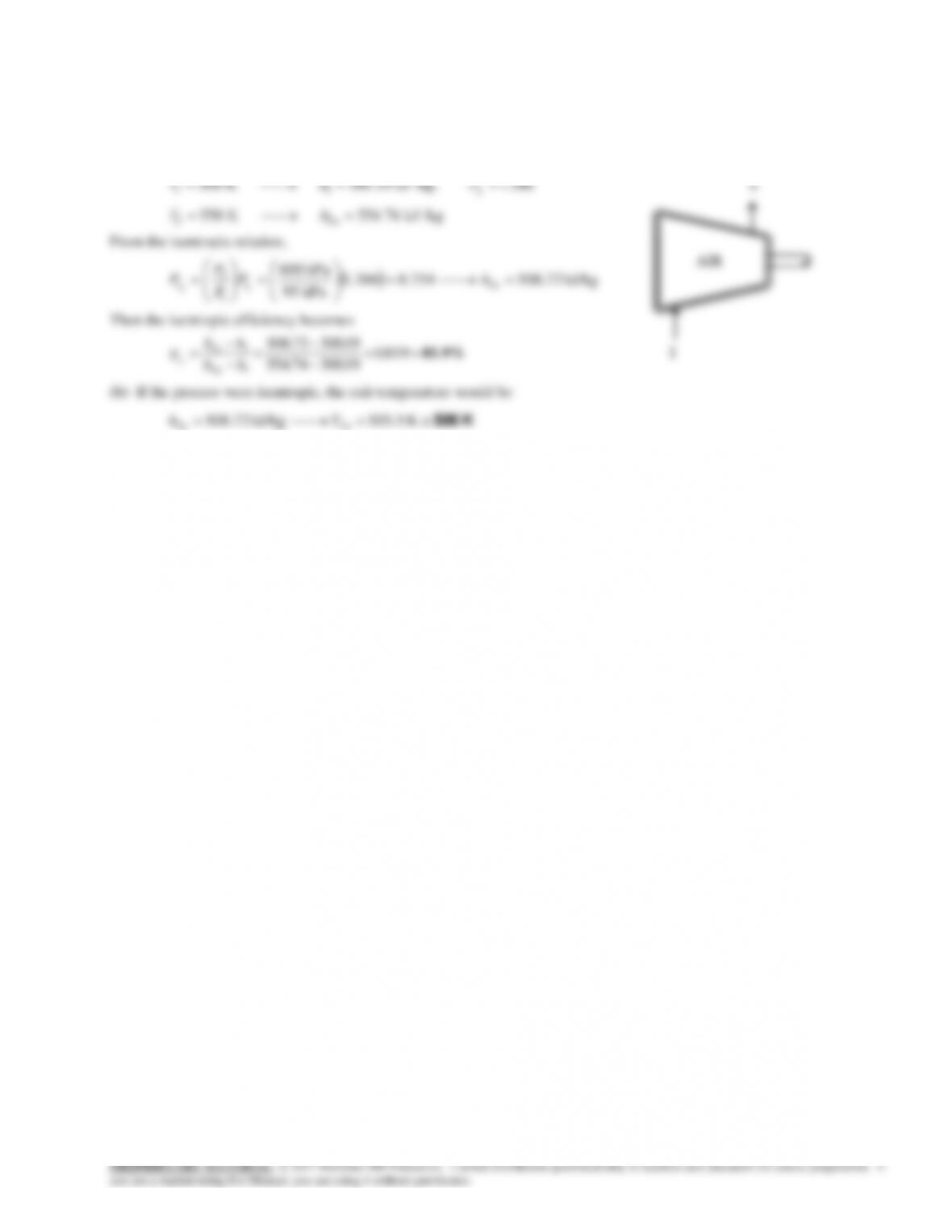
8-122 Air is compressed by an adiabatic compressor from a specified state to another specified state. The isentropic
efficiency of the compressor and the exit temperature of air for the isentropic case are to be determined.
Assumptions 1 This is a steady-flow process since there is no change with time. 2 Kinetic and potential energy changes are
negligible. 3 The device is adiabatic and thus heat transfer is negligible. 4 Air is an ideal gas with variable specific heats.
Analysis (a) From the air table (Table A-21),
T h P
r
1 1
11386
300 K 300.19 kJ /kg,
.
2