6-82
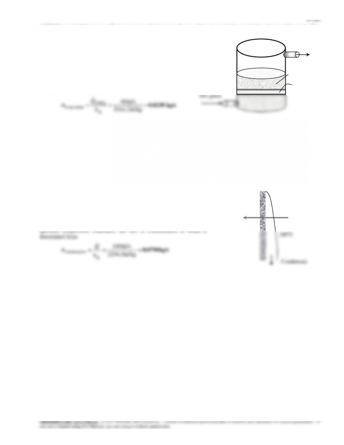
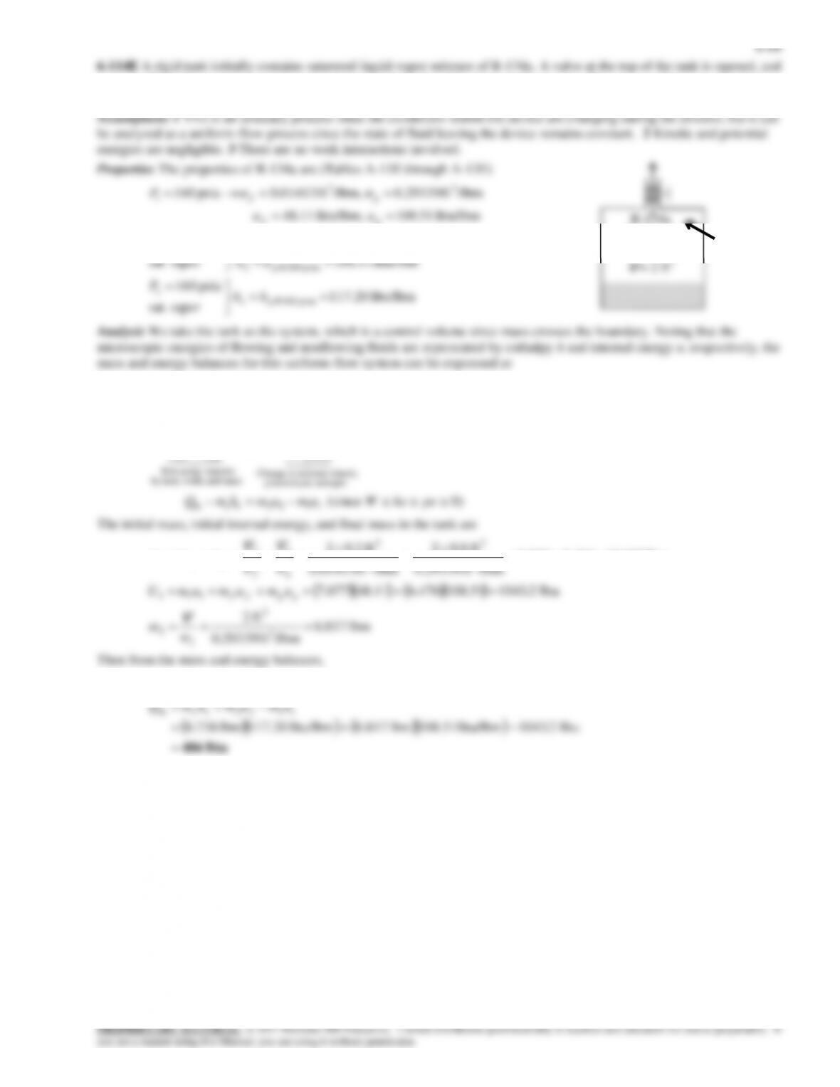
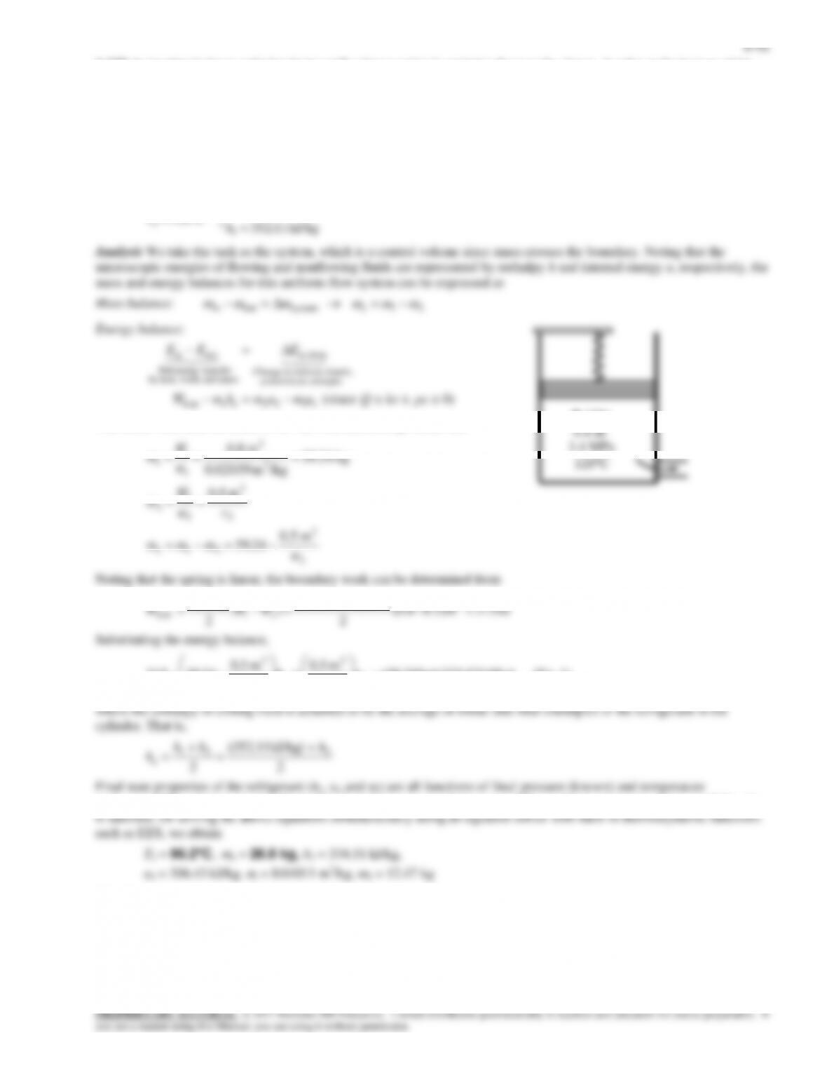
6-112 A rigid tank initially contains saturated R–134a vapor. The tank is connected to a supply line, and R-134a is allowed
to enter the tank. The mass of the R-134a that entered and the heat transfer are to be determined.
Assumptions 1 This is an unsteady process since the conditions within the device are changing during the process, but it can
be analyzed as a uniform-flow process since the state of fluid at the inlet remains constant. 2 Kinetic and potential energies
are negligible. 3 There are no work interactions involved. 4 The direction of heat transfer is to the tank (will be verified).
Properties The properties of refrigerant are (Tables A-11 through A-13)
/kgm 0.0008935
MPa 1.2
kJ/kg 246.82
/kgm 0.02565
vaporsat.
MPa 8.0
3
MPa 1.2@2
2
MPa 8.0@1
3
MPa 8.0@1
1
f
g
g
P
uu
P
vv
vv
1.2 MPa
36C
R-134a
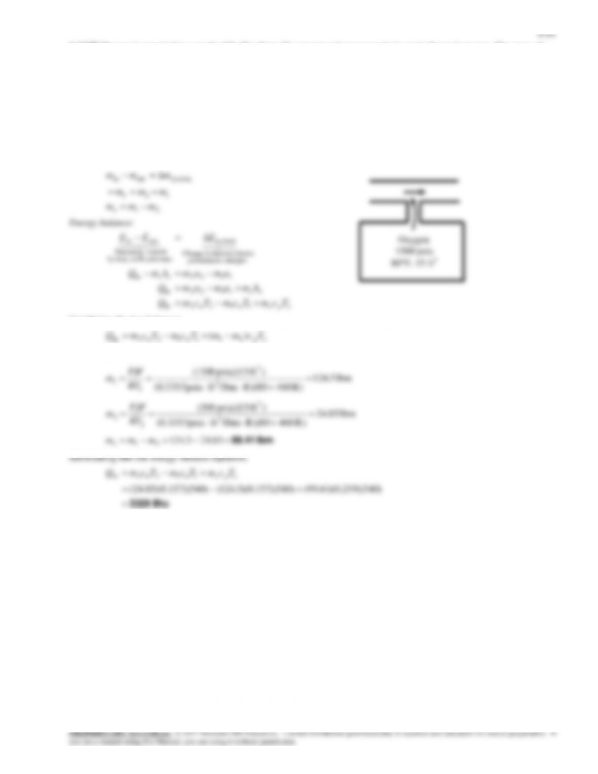
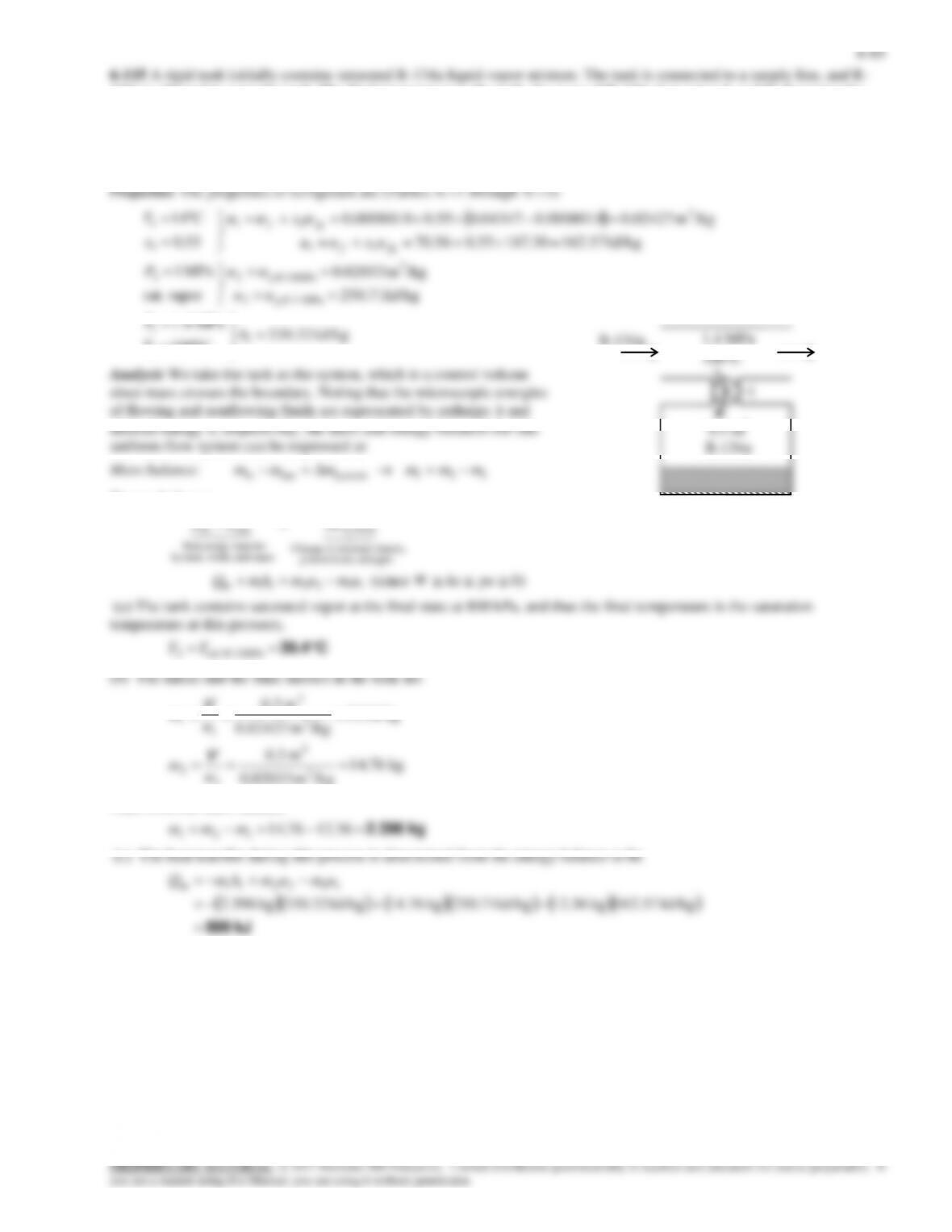
vapor is allowed to escape at constant pressure until all the liquid in the tank disappears. The amount of heat transfer is to
be determined.
Btu/lbm 117.20
vaporsat.
psia 160
Btu/lbm 108.51
/lbmft 0.29339
vaporsat.
psia 160
Btu/lbm 51.108 Btu/lbm, 11.48
/lbmft 0.29339 /lbm,ft 0.01413 psia 160
psia 160@
psia 160@2
3
psia 160@2
2
33
1
ge
e
g
g
gf
gf
hh
P
uu
v
P
uu
P
v
vv
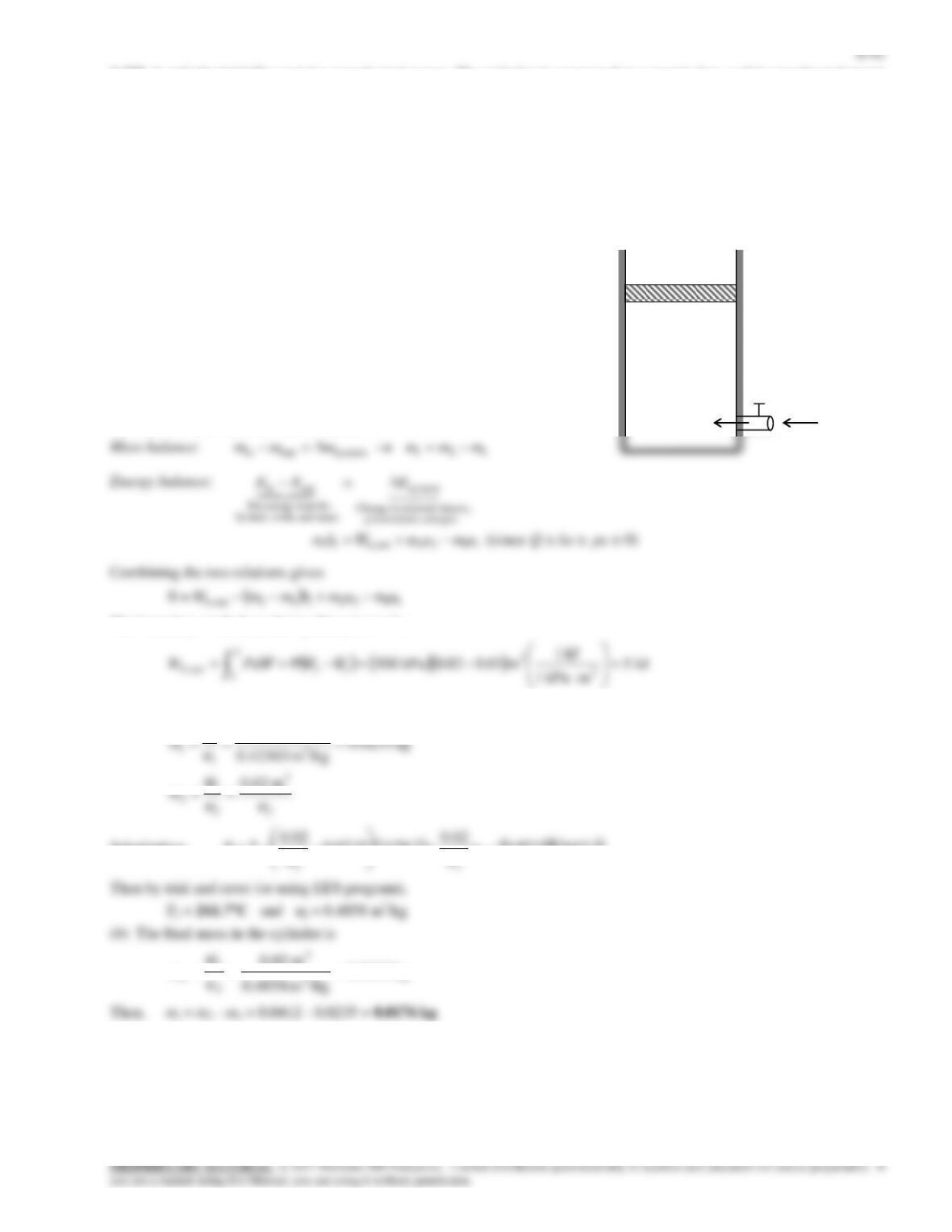
Mass balance:
21systemoutin mmmmmm e
Energy balance:
kinetic, internal,in Change
system
nsferenergy traNet
outin
EEE
R-134a
Sat. vapor
P = 160 psia
V
= 2 ft3
Q
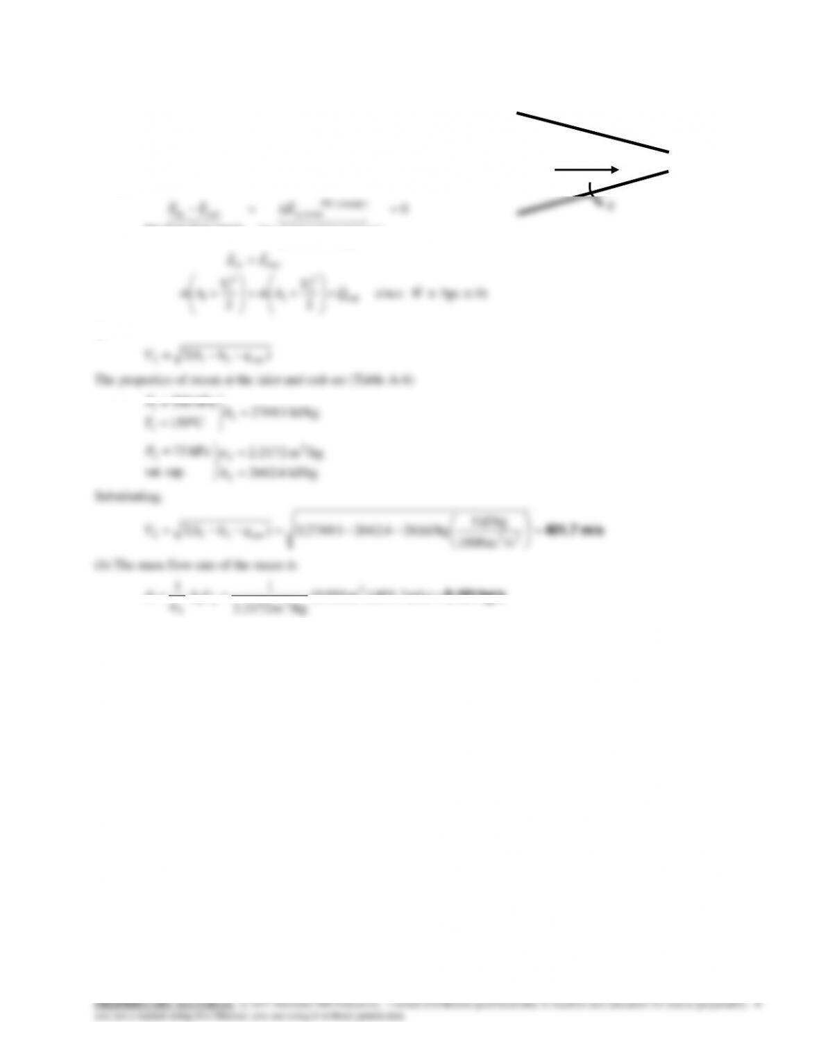
134a is allowed to enter the tank. The final temperature in the tank, the mass of R-134a that entered, and the heat transfer
are to be determined.
Assumptions 1 This is an unsteady process since the conditions within the device are changing during the process, but it can
be analyzed as a uniform-flow process since the state of fluid at the inlet remains constant. 2 Kinetic and potential energies
are negligible. 3 There are no work interactions involved. 4 The direction of heat transfer is to the tank (will be verified).
PROPRIETARY MATERIAL. © 2017 McGraw-Hill Education. Limited distribution permitted only to teachers and educators for course preparation. If
you are a student using this Manual, you are using it without permission.
expands the balloon skin are to be determined.
Assumptions 1 This is an unsteady process since the conditions within the device are changing during the process, but it can
be analyzed as a uniform-flow process. 2 Air is an ideal gas with constant specific heats. 3 Kinetic and potential energies are
negligible. 4 There is no heat transfer.
Properties The gas constant of air is 0.287 kPa·m3/kg·K (Table A-1).
Analysis The specific volume of the air at the entrance and exit, and in the balloon is
kPa 100
)K 27335)(K/kgmkPa 0.287( 3
3
RT
The mass flow rate at the entrance is then
)m/s 2()m 1(
2
ii
VA
6-88
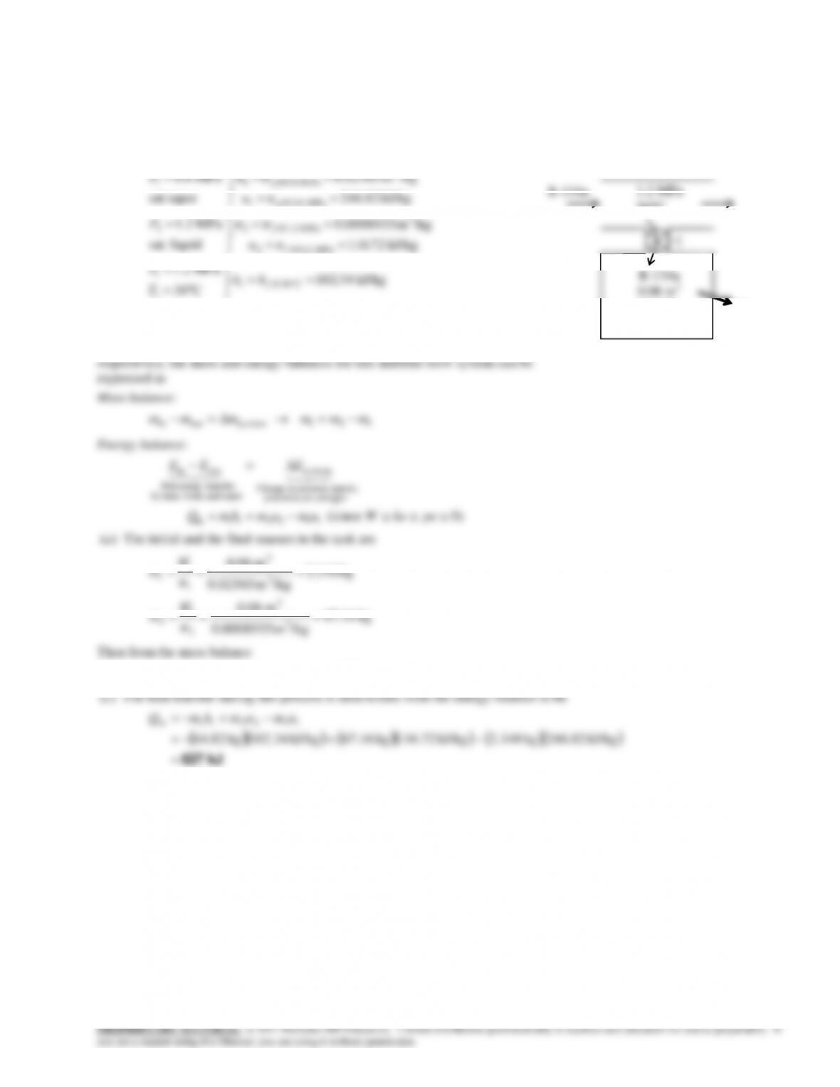
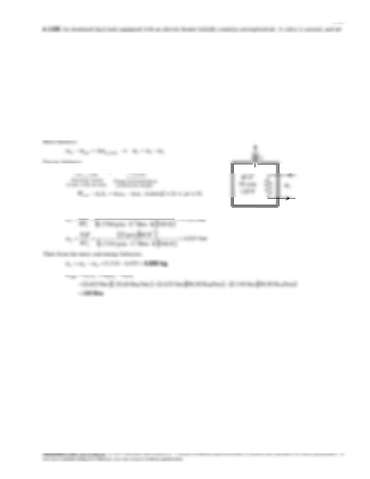
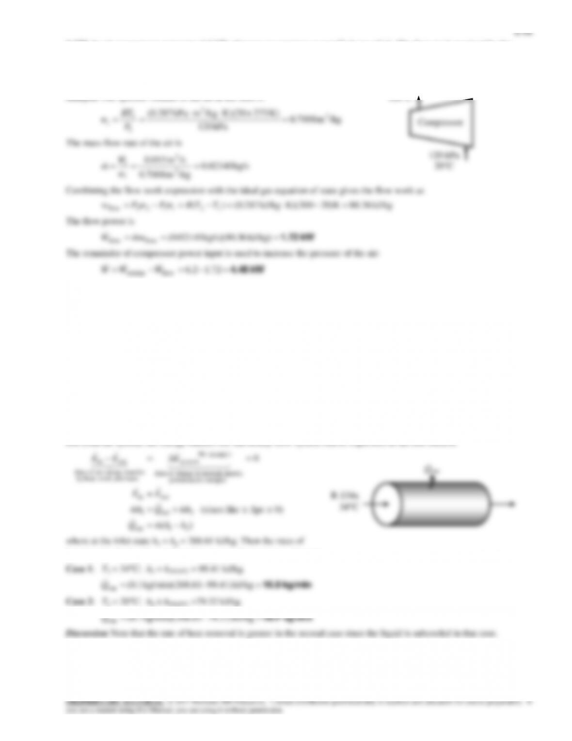
6-118E An insulated rigid tank equipped with an electric heater initially contains pressurized air. A valve is opened, and air
is allowed to escape at constant temperature until the pressure inside drops to 25 psia. The amount of electrical work
transferred is to be determined.
Assumptions 1 This is an unsteady process since the conditions within the device are changing during the process, but it can
be analyzed as a uniform-flow process since the exit temperature (and enthalpy) of air remains constant. 2 Kinetic and
potential energies are negligible. 3 The tank is insulated and thus heat transfer is negligible. 4 Air is an ideal gas with
variable specific heats.
Properties The gas constant of air is R =0.3704 psia.ft3/lbm.R (Table A-1E). The properties of air are (Table A-21E)
T h
T u
T u
i i
580 R 138.66 Btu / lbm
580 R 98.90 Btu / lbm
580 R 98.90 Btu / lbm
1 1
2 2
Analysis We take the tank as the system, which is a control volume since mass crosses the boundary. Noting that the
microscopic energies of flowing and nonflowing fluids are represented by enthalpy h and internal energy u, respectively, the
mass and energy balances for this uniform-flow system can be expressed as
Energy balance:
kinetic, internal,in Change
system
nsferenergy traNet
outin
EEE
AIR
40 ft3
6-90
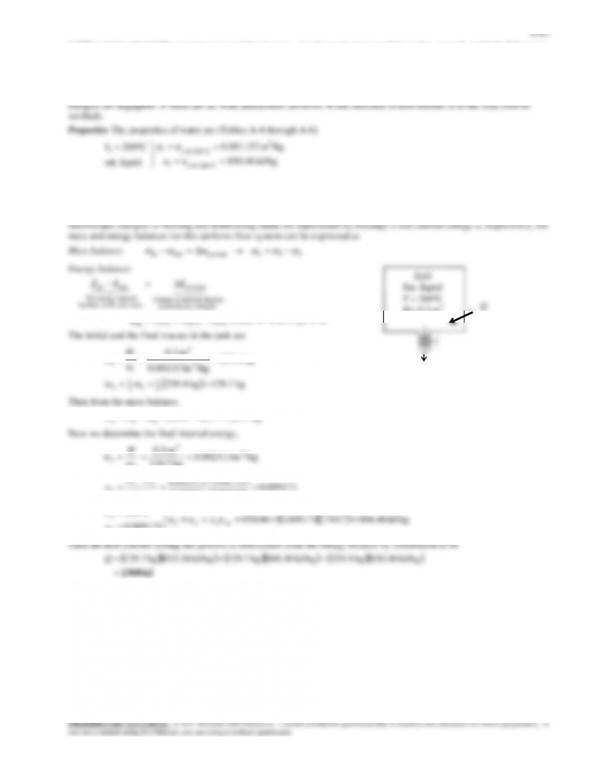
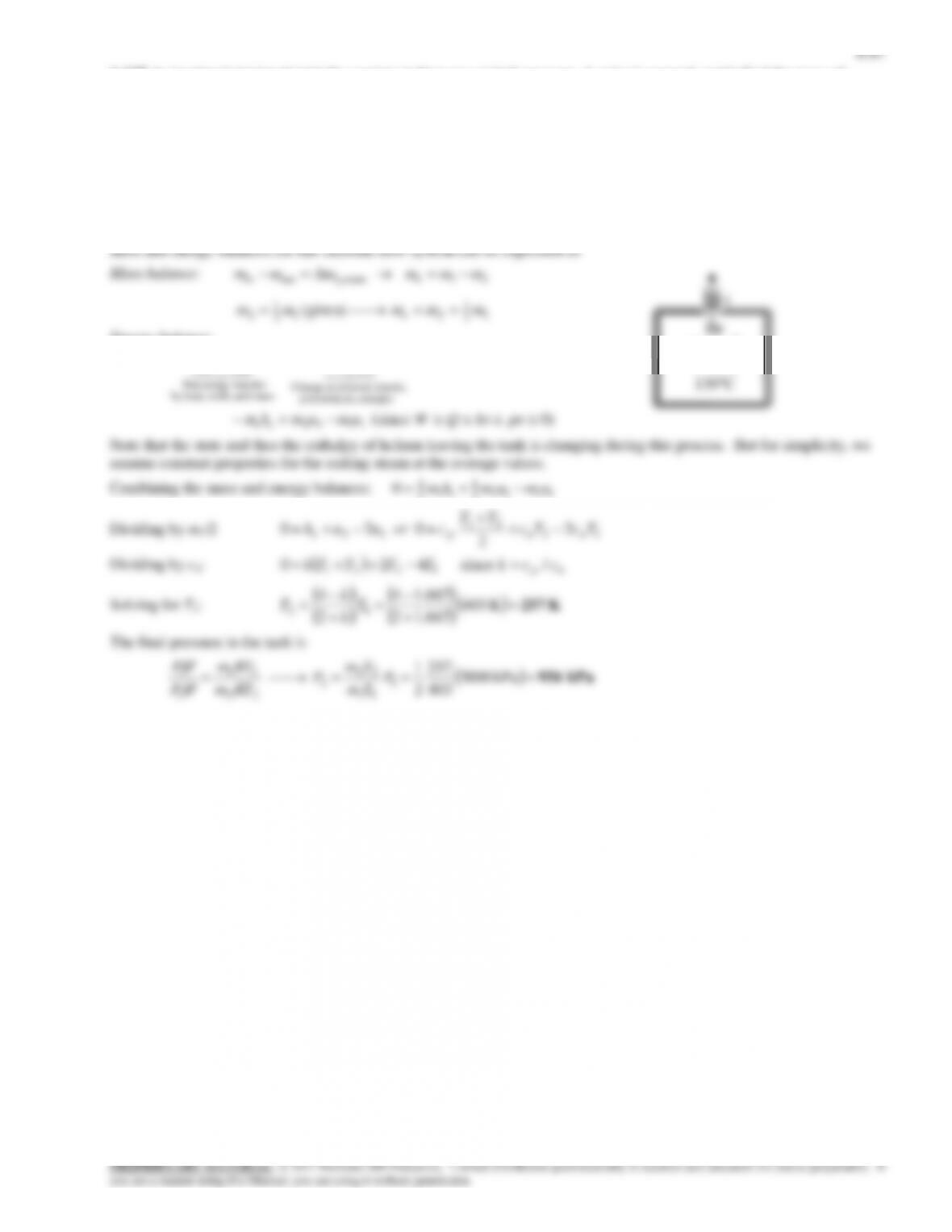
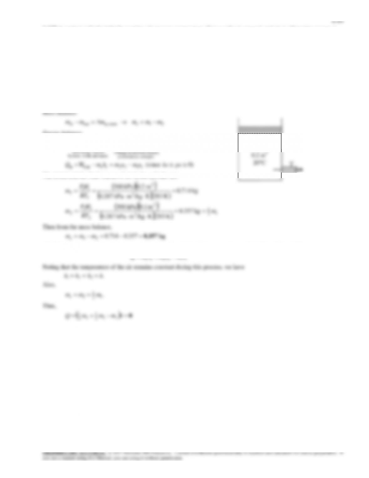
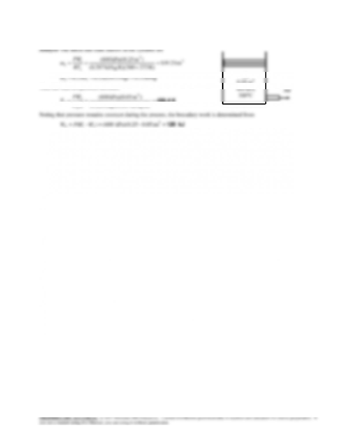
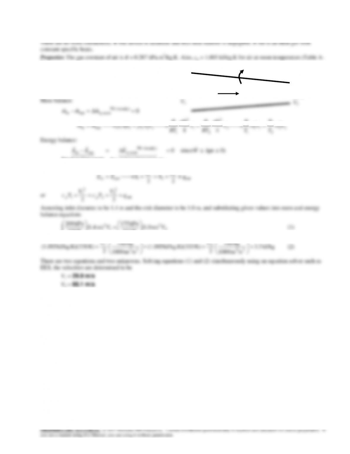
6-120 A vertical piston-cylinder device contains air at a specified state. Air is allowed to escape from the cylinder by a
valve connected to the cylinder. The final temperature and the boundary work are to be determined.
Properties The gas constant of air is R = 0.287 kJ/kg.K (Table A-1).
Then the final temperature becomes
K 458.4 kJ/kg.K) 287.0(kg) 2280.0(
)m kPa)(0.05 600( 3
2
2
2Rm
P
T
V
21 0.05)mkPa)(0.25 (600)(
0.25 m3
600 kPa
300C
Air
6-93
Review Problems
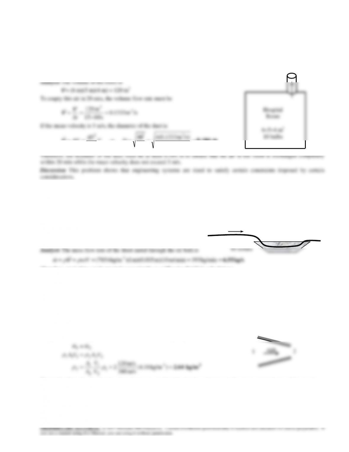
6-123 The air in a hospital room is to be replaced every 15 minutes. The minimum diameter of the duct is to be determined
if the air velocity is not to exceed a certain value.
Assumptions 1 The volume occupied by the furniture etc in the room is negligible. 2 The incoming conditioned air does not
mix with the air in the room.
m 0.184 m/s) (5
/s)m 1333.0(44
4
32
V
DV
D
AV
V
V
6-124 A long roll of large 1-Mn manganese steel plate is to be quenched in an oil bath at a specified rate. The mass flow
rate of the plate is to be determined.
Assumptions The plate moves through the bath steadily.
Properties The density of steel plate is given to be = 7854 kg/m3.
Therefore, steel plate can be treated conveniently as a “flowing fluid” in calculations.
6-125 Air is accelerated in a nozzle. The density of air at the nozzle exit is to be determined.
Assumptions Flow through the nozzle is steady.
Properties The density of air is given to be 4.18 kg/m3 at the inlet.
Analysis There is only one inlet and one exit, and thus
m m m
1 2
. Then,
3
kg/m 2.64
) kg/m18.4(
m/s 380
m/s 120
23
1
2
1
2
1
2
222111
21
V
V
A
A
mm
Discussion Note that the density of air decreases considerably despite a decrease in the cross-sectional area of the nozzle.
AIR
1
2
654 m3
10 bulbs
Steel plate
6-98
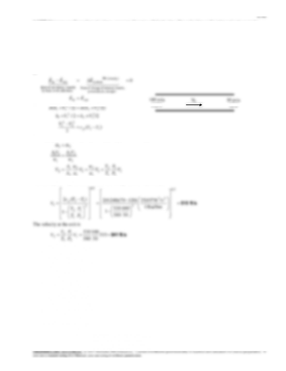
6-132 Air flows through a non-constant cross-section pipe. The inlet and exit velocities of the air are to be determined.
Assumptions 1 This is a steady-flow process since there is no change with time. 2 Potential energy change is negligible. 3
2)
Analysis We take the pipe as the system, which is a
control volume since mass crosses the boundary.
The mass and energy balances for this steady-flow
system can be expressed in the rate form as
D1
200 kPa
65C
D2
175 kPa
60C
Air
q
6-99
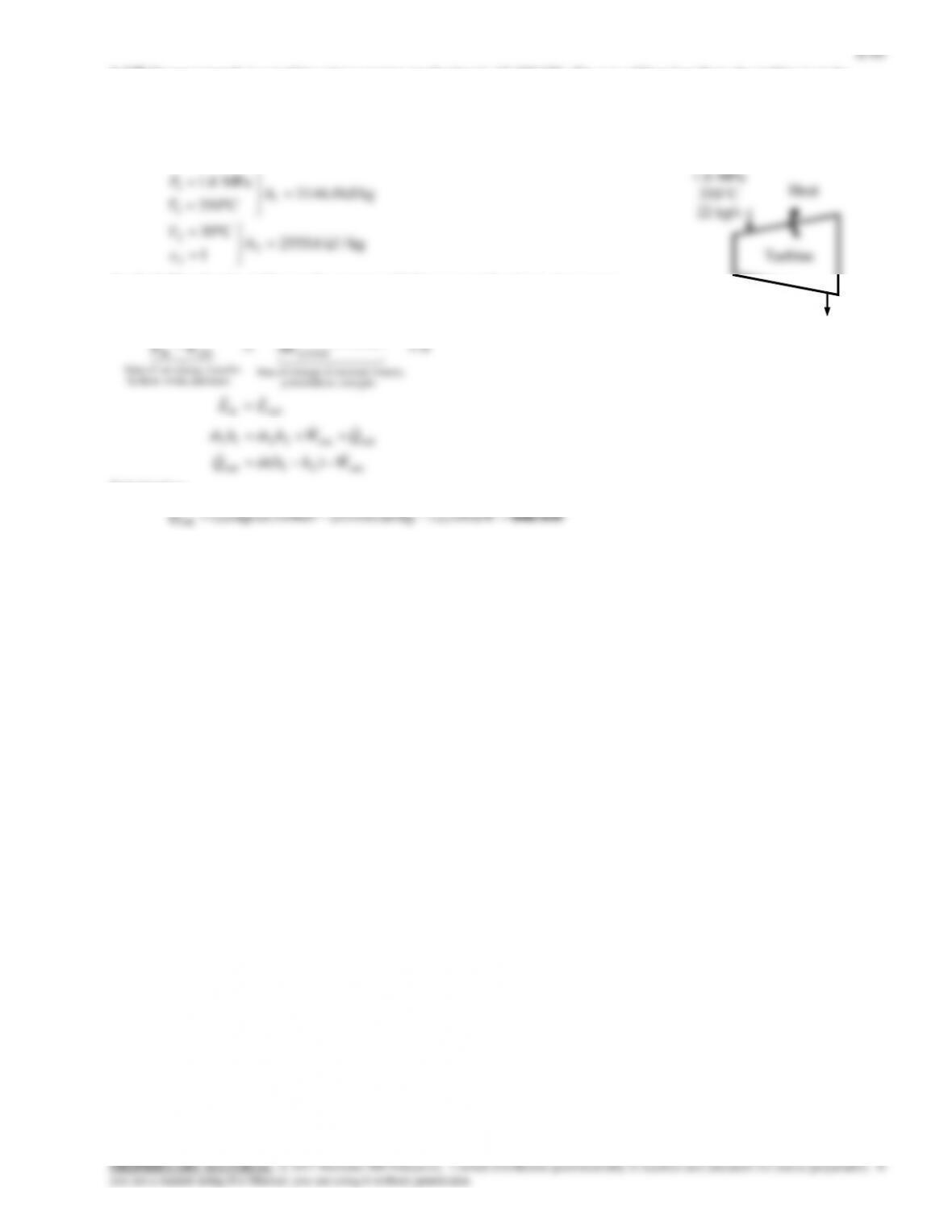
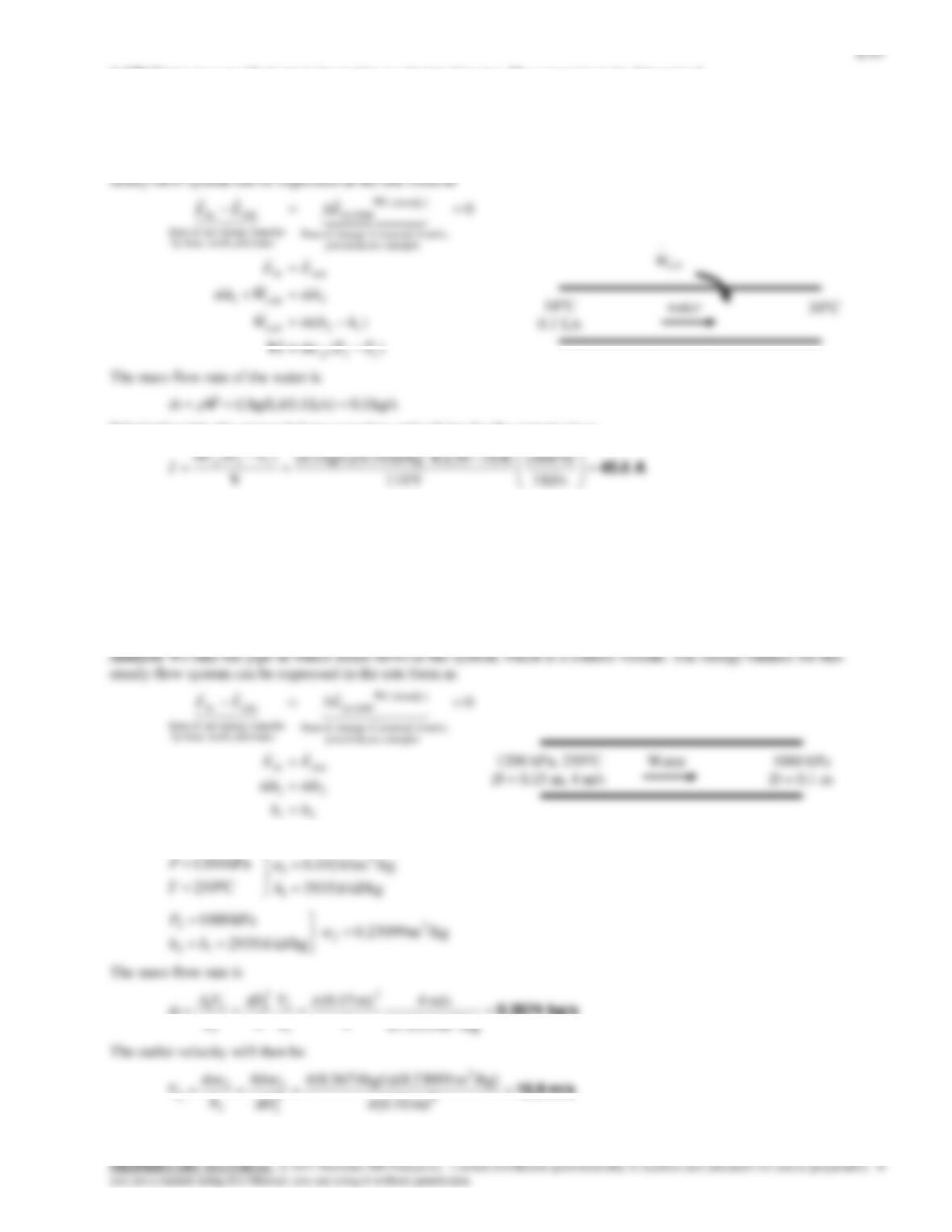
6-133 Heat is lost from the steam flowing in a nozzle. The exit velocity and the mass flow rate are to be determined.
Assumptions 1 This is a steady-flow process since there is no change
with time. 2 Potential energy change is negligible. 3 There are no
work interactions.
Analysis (a) We take the steam as the system, which is a control
volume since mass crosses the boundary. The energy balance for this
steady-flow system can be expressed in the rate form as
Energy balance:
0)pe since
22
0
out
2
2
2
2
1
1
outin
energies etc. potential,
kinetic, internal,in change of Rate
(steady) 0
sy stem
mass and work,heat,by
nsferenergy tranet of Rate
outin
WQ
V
hm
V
hm
EE
EEE
or
)(2 out212 qhhV
The properties of steam at the inlet and exit are (Table A-6)
kJ/kg 1.2769
C150
kPa 002
1
1
1
h
T
P
kJ/kg 4.2662
/kgm 2172.2
vap.sat.
kPa 75
2
3
2
2
h
P
v
Substituting,
m/s 401.7
22
out212 /sm 1000
kJ/kg 1
kJ/kg)264.26621.2769(2)(2 qhhV
(b) The mass flow rate of the steam is
kg/s 0.181 m/s) )(401.7m (0.001
/kgm 2.2172
11 2
3
22
2
VAm
v
150C
200 kPa
STEAM
q
75 kPa
Sat. vap.