6-41
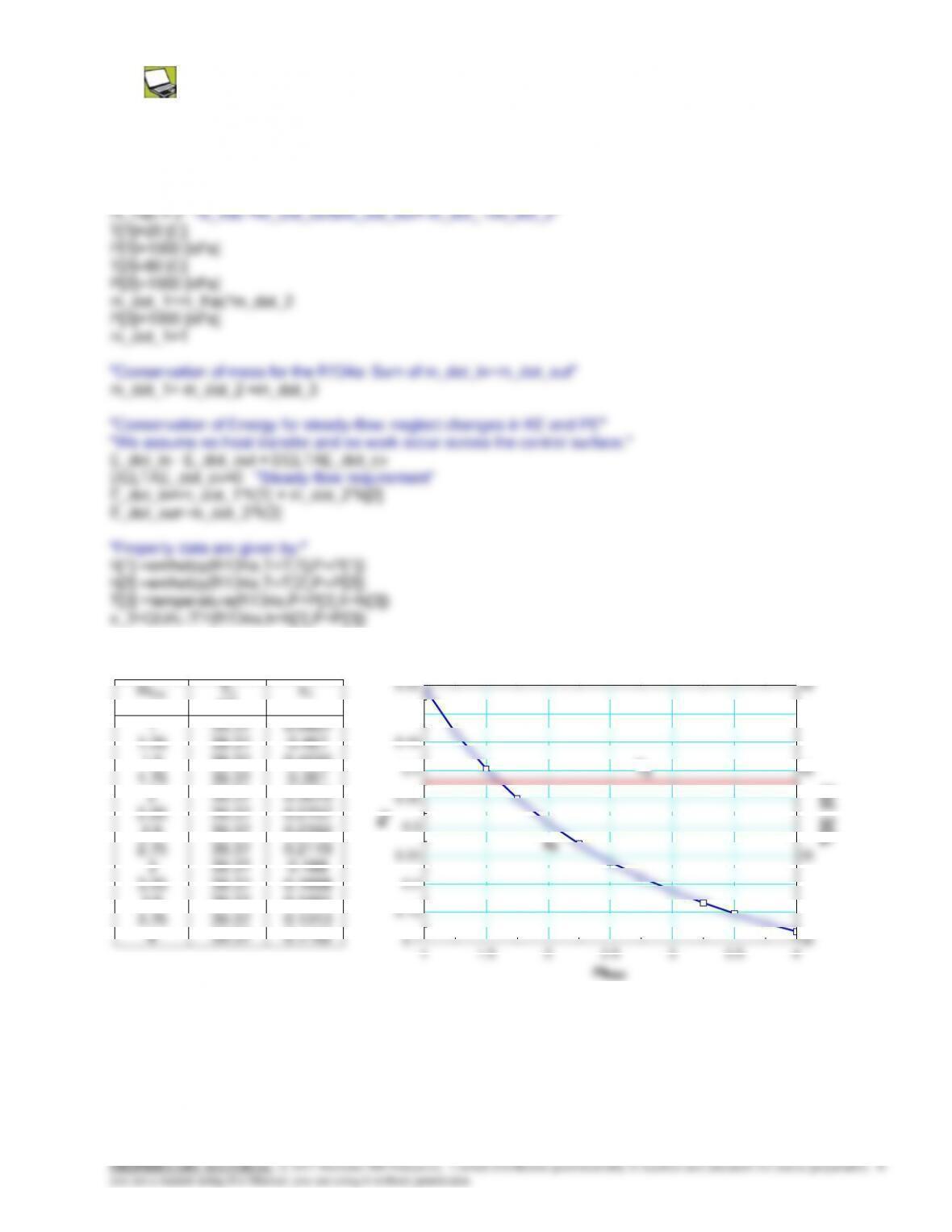
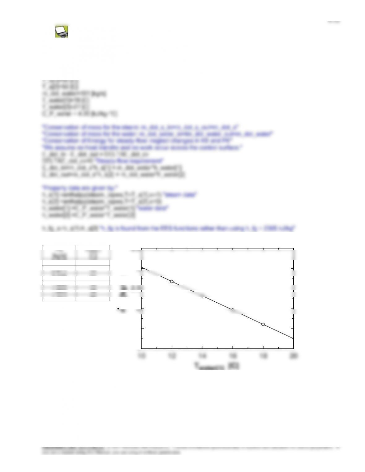
6-68 Problem 6-67 is reconsidered. The effect of the mass flow rate of the cold stream of R-134a on the temperature
and the quality of the exit stream as the ratio of the mass flow rate of the cold stream to that of the hot stream varies from 1
to 4 is to be investigated. The mixture temperature and quality are to be plotted against the cold–to-hot mass flow rate ratio.
Analysis The problem is solved using EES, and the solution is given below.
“Input Data”
mfrac
T3
[C]
x3
1
1.25
1.5
1.75
2
2.25
2.5
2.75
3
3.25
3.5
3.75
39.37
39.37
39.37
39.37
39.37
39.37
39.37
39.37
39.37
39.37
39.37
39.37
0.5467
0.467
0.4032
0.351
0.3075
0.2707
0.2392
0.2119
0.188
0.1668
0.1481
0.1313
0.15
0.2
0.25
0.3
0.35
0.4
0.45
0.5
0.55
35
40
45
x3
T[3] [C]
T3
x3
6-42
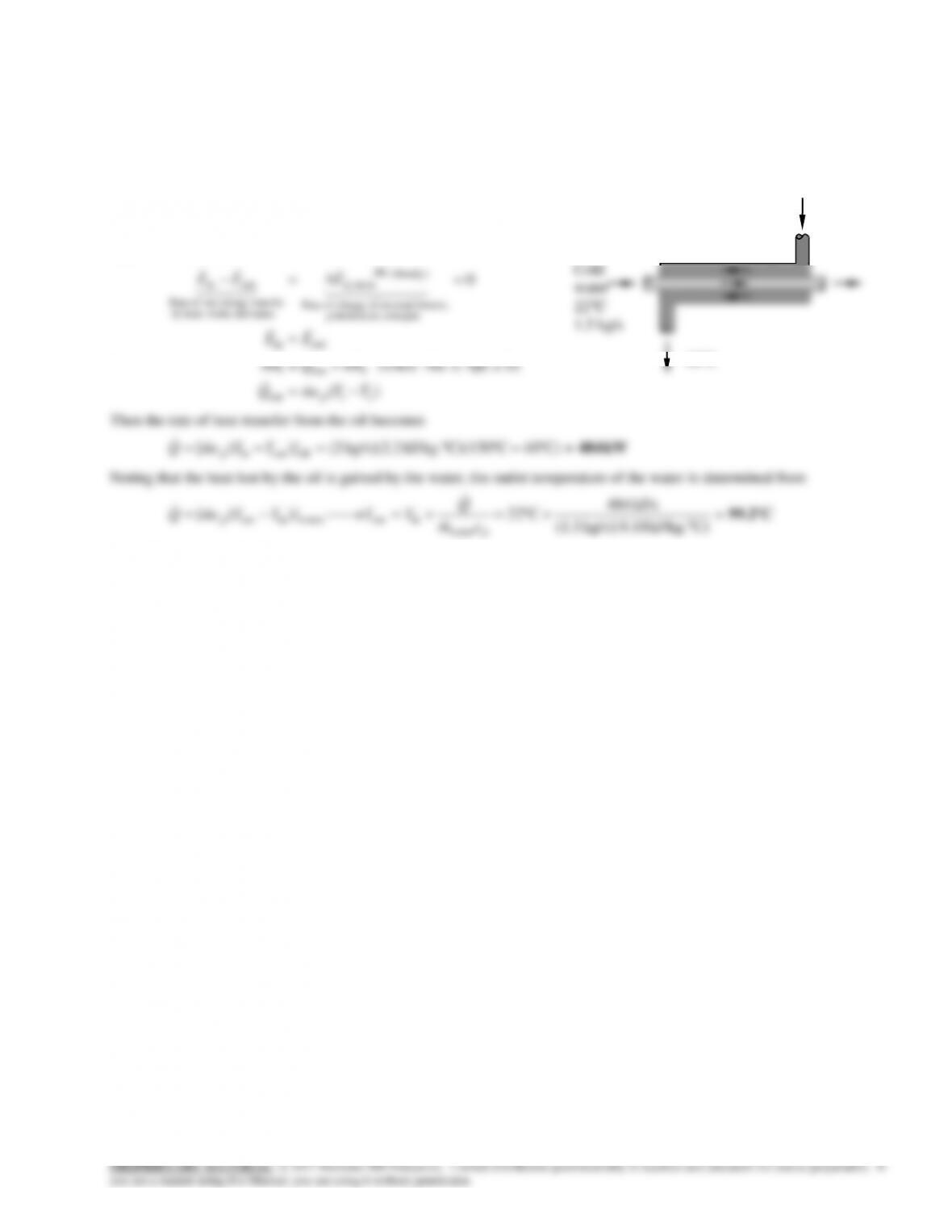
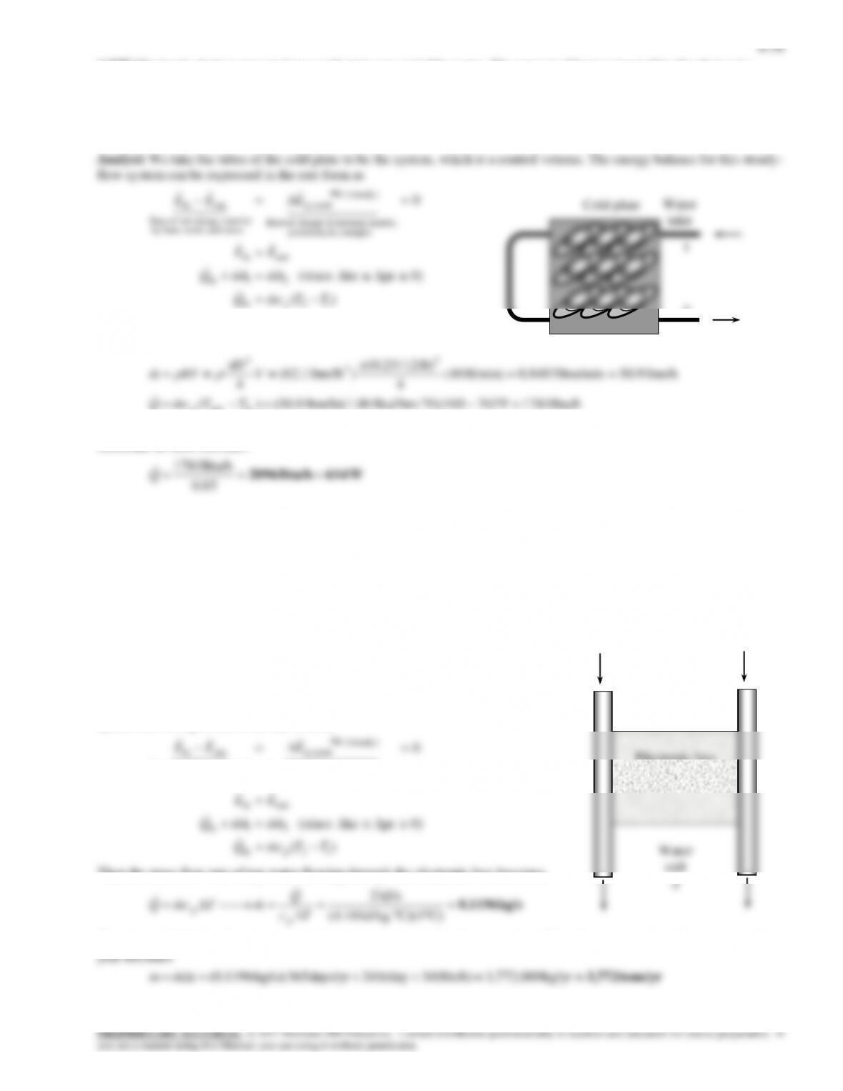
6-69 Water is heated in a heat exchanger by geothermal water. The rate of heat transfer to the water and the exit temperature
of the geothermal water is to be determined.
Assumptions 1 Steady operating conditions exist. 2 The heat exchanger is well-insulated so that heat loss to the
surroundings is negligible and thus heat transfer from the hot fluid is equal to the heat transfer to the cold fluid. 3 Changes
in the kinetic and potential energies of fluid streams are negligible. 4 Fluid properties are constant.
Properties The specific heats of water and geothermal fluid are given to be 4.18 and 4.31 kJ/kg.C, respectively.
Analysis We take the cold water tubes as the system, which is a control volume. The
energy balance for this steady-flow system can be expressed in the rate form as
0
energies etc. potential,
kinetic, internal,in change of Rate
(steady) 0
sy stem
mass and work,heat,by
nsferenergy tranet of Rate
outin
EEE
Brine
60C
6-43
6-70E Steam is condensed by cooling water in a condenser. The rate of heat transfer in the heat exchanger and the rate of
condensation of steam are to be determined.
Assumptions 1 Steady operating conditions exist. 2 The heat exchanger is well-insulated so that heat loss to the
surroundings is negligible and thus heat transfer from the hot fluid is equal to the heat transfer to the cold fluid. 3 Changes
in the kinetic and potential energies of fluid streams are negligible. 4 Fluid properties are constant.
Properties The specific heat of water is 1.0 Btu/lbm.F (Table A-3E). The
enthalpy of vaporization of water at 75F is 1050.9 Btu/lbm (Table A-4E).
Analysis We take the tube-side of the heat exchanger where cold water is
flowing as the system, which is a control volume. The energy balance for
this steady-flow system can be expressed in the rate form as
0
energies etc. potential,
kinetic, internal,in change of Rate
(steady) 0
sy stem
mass and work,heat,by
nsferenergy tranet of Rate
outin
EEE
Steam
75F
65F
6-44
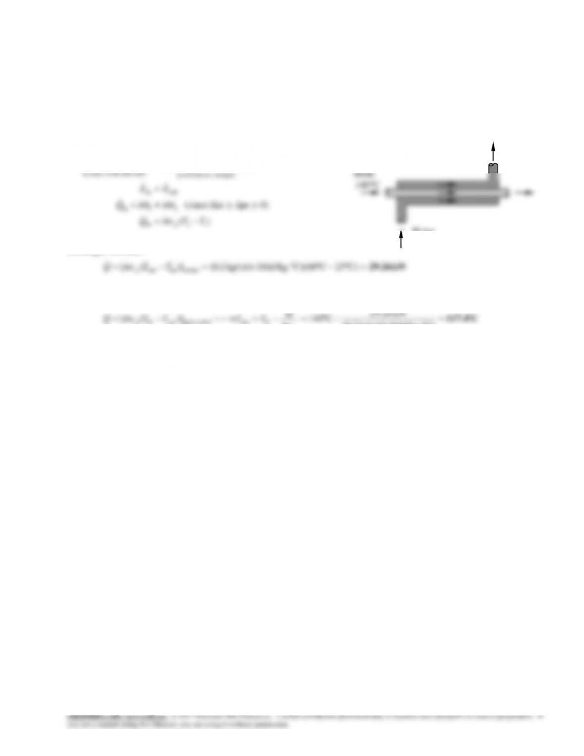
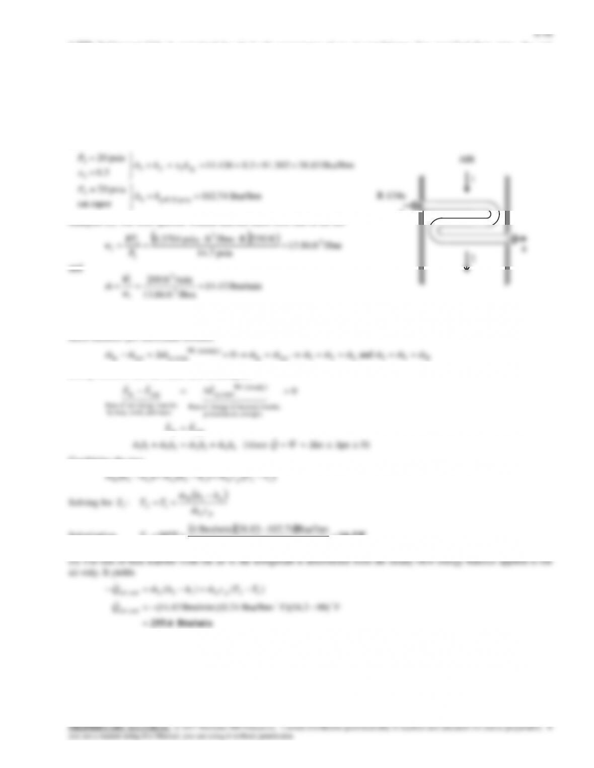
6-71 Oil is to be cooled by water in a thin-walled heat exchanger. The rate of heat transfer in the heat exchanger and the exit
temperature of water is to be determined.
Assumptions 1 Steady operating conditions exist. 2 The heat exchanger is well-insulated so that heat loss to the
surroundings is negligible and thus heat transfer from the hot fluid is equal to the heat transfer to the cold fluid. 3 Changes
in the kinetic and potential energies of fluid streams are negligible. 4 Fluid properties are constant.
Properties The specific heats of water and oil are given to be 4.18
and 2.20 kJ/kg.C, respectively.
Analysis We take the oil tubes as the system, which is a control
volume. The energy balance for this steady-flow system can be
expressed in the rate form as
)(
0)peke (since
0
21out
2out1
outin
energies etc. potential,
kinetic, internal,in change of Rate
(steady) 0
sy stem
mass and work,heat,by
nsferenergy tranet of Rate
outin
TTcmQ
hmQhm
EE
EEE
p
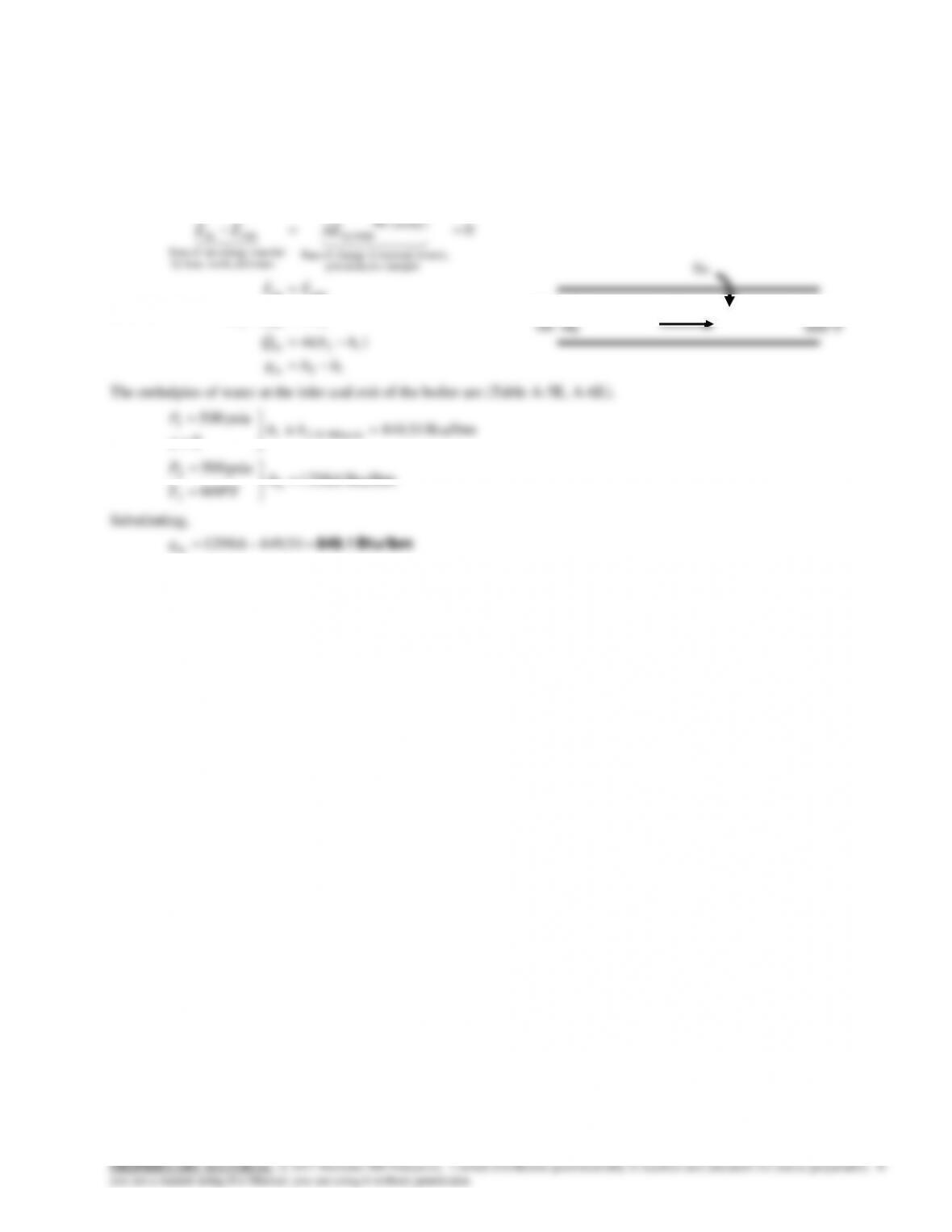
Then the rate of heat transfer from the oil becomes
=C)40CC)(150kJ/kg. kg/s)(2.2 2()]([ oiloutin kW 484 TTcmQ p
Noting that the heat lost by the oil is gained by the water, the outlet temperature of the water is determined from
C99.2
=
C)kJ/kg. kg/s)(4.18 (1.5
kJ/s 484
C22 )]([
water
inoutwaterinout
p
pcm
Q
TTTTcmQ
Cold
water
22C
1.5 kg/s
Hot oil
150C
2 kg/s
40C
6-47
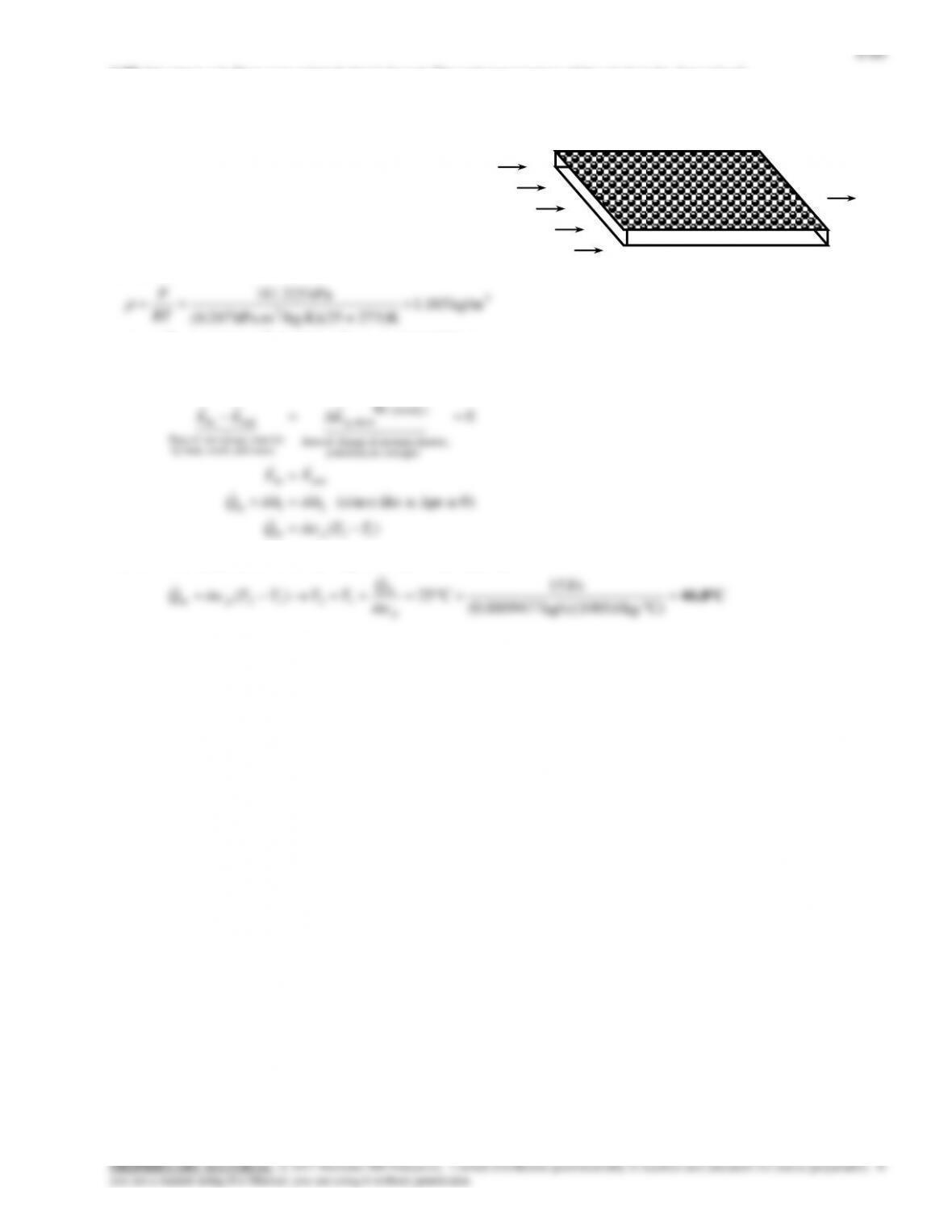
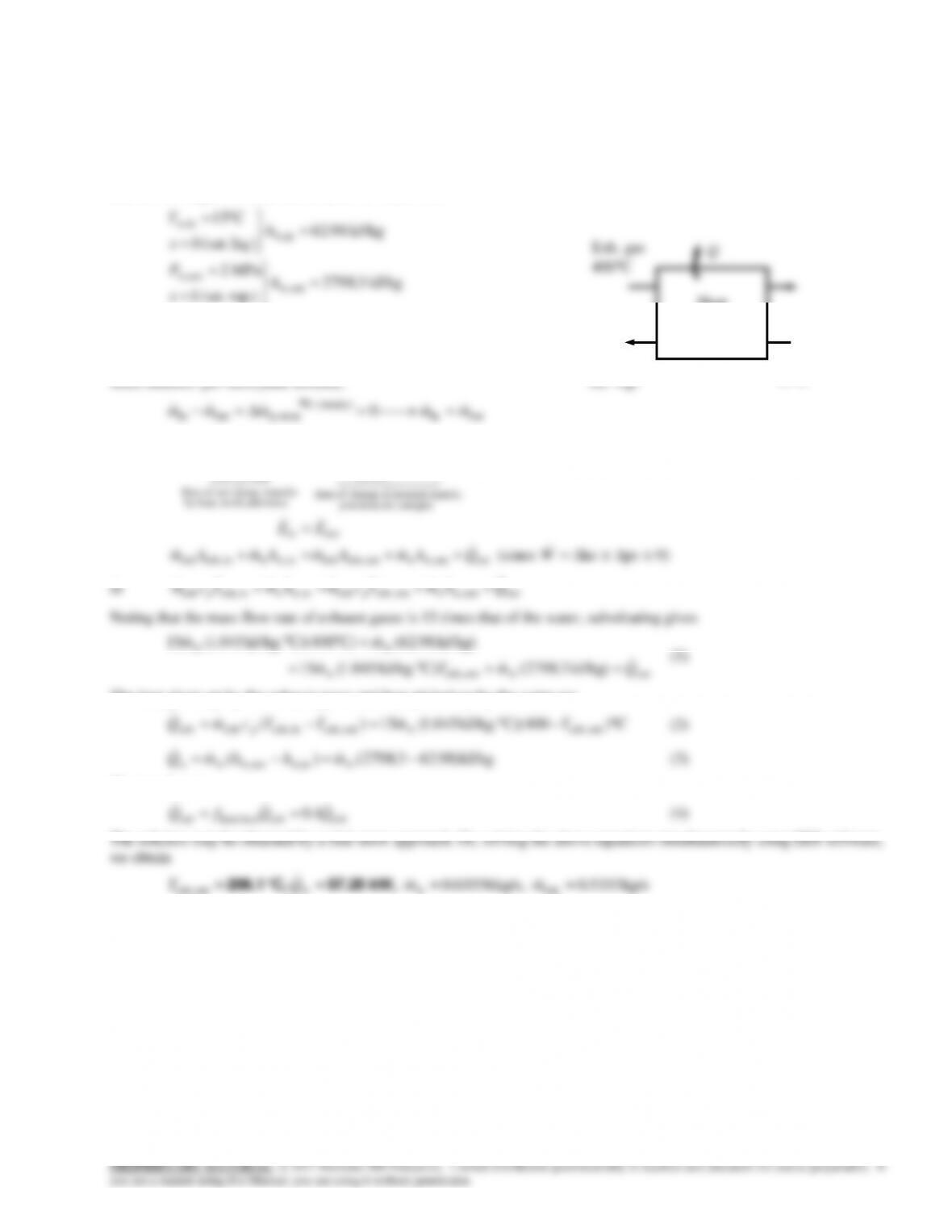
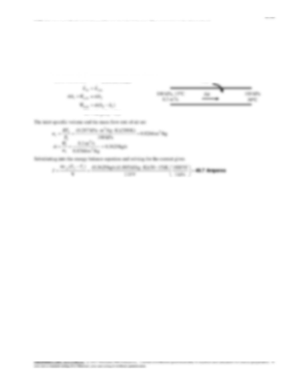
6-74 Refrigerant-134a is to be cooled by air in the condenser. For a specified volume flow rate of air, the mass flow rate of
the refrigerant is to be determined.
Assumptions 1 This is a steady-flow process since there is no change with time. 2 Kinetic and potential energy changes are
negligible. 3 There are no work interactions. 4 Heat loss from the device to the surroundings is negligible and thus heat
transfer from the hot fluid is equal to the heat transfer to the cold fluid. 5 Air is an ideal gas with constant specific heats at
room temperature.
Properties The gas constant of air is 0.287 kPa.m3/kg.K (Table A-1). The constant pressure specific heat of air is cp = 1.005
kJ/kg·°C (Table A-2). The enthalpies of the R-134a at the inlet and the exit states are (Tables A-11 through A-13)
kJ/kg 93.58
C30
MPa 1
kJ/kg 324.66
C09
MPa 1
30@
4
4
4
3
3
3
Cf
hh
T
P
h
T
P
Analysis The inlet specific volume and the mass flow rate of air are
2
/kgm 0.861
kPa 100
K 300K/kgmkPa 0.287
3
3
1
1
1
v
P
RT
AIR
R-134a
3
4
1
6-49
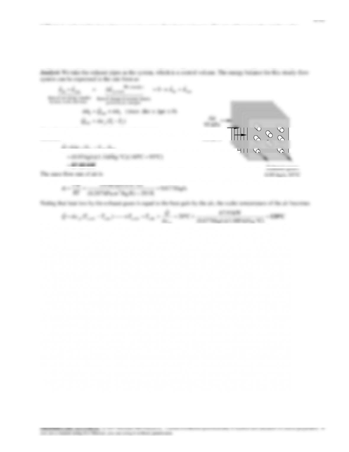
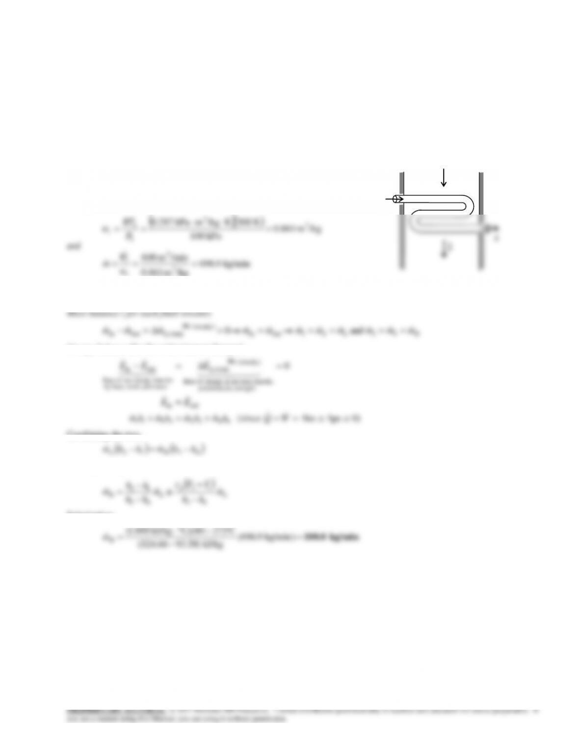
6-76 A heat exchanger that is not insulated is used to produce steam from the heat given up by the exhaust gases of an
internal combustion engine. The temperature of exhaust gases at the heat exchanger exit and the rate of heat transfer to the
water are to be determined.
Assumptions 1 This is a steady-flow process since there is no change with time. 2 Kinetic and potential energy changes are
negligible. 3 There are no work interactions. 4 Exhaust gases are assumed to have air properties with constant specific heats.
Properties The constant pressure specific heat of the exhaust gases is taken to be cp = 1.045 kJ/kg·°C (Table A–2). The inlet
and exit enthalpies of water are (Tables A-4 and A-5)
kJ/kg 98.62
liq.) (sat. 0
C15
inw,
inw,
h
x
T
Q
Exh. gas
6-53
Pipe and duct Flow
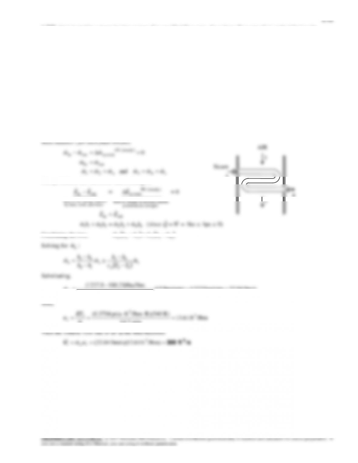
6-80E Saturated liquid water is heated in a steam boiler. The heat transfer per unit mass is to be determined.
Assumptions 1 This is a steady-flow process since there is no change with time. 2 Kinetic and potential energy changes are
negligible. 3 There are no work interactions.
Analysis We take the pipe in which the water is heated as the system, which is a control volume. The energy balance for this
steady-flow system can be expressed in the rate form as
12in
12in
2in1
outin
energies etc. potential,
kinetic, internal,in change of Rate
(steady) 0
sy stem
mass and work,heat,by
nsferenergy tranet of Rate
outin
)(
0
hhq
hhmQ
hmQhm
EE
EEE
Btu/lbm 6.1298
F600
psia 500
Btu/lbm 51.449
0
psia 500
2
2
2
psia 500@1
1
h
T
P
hh
x
P
f
Substituting,
Btu/lbm 849.1 51.4496.1298
in
q
500 psia
600F
Water
500 psia,
sat. liq.
qin
6-55
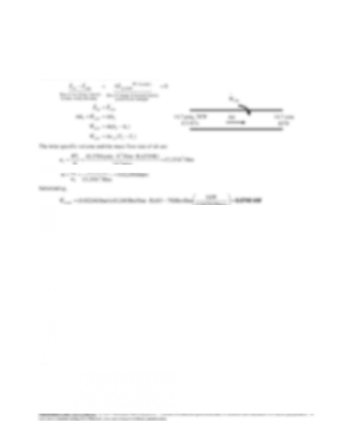
6-82E The cooling fan of a computer draws air, which is heated in the computer by absorbing the heat of PC circuits. The
electrical power dissipated by the circuits is to be determined.
Assumptions 1 This is a steady-flow process since there is no change with time. 2 Kinetic and potential energy changes are
negligible. 3 All the heat dissipated by the circuits are picked up by the air drawn by the fan.
Properties The gas constant of air is 0.3704 psia·ft3/lbm·R (Table A-1E). The constant pressure specific heat of air at room
temperature is cp = 0.240 Btu/lbm·°F (Table A–2Ea).
Analysis We take the pipe in which the air is heated as the system, which is a control volume. The energy balance for this
steady-flow system can be expressed in the rate form as
0
outin
energies etc. potential,
kinetic, internal,in change of Rate
(steady) 0
system
mass and work,heat,by
nsferenergy tranet of Rate
outin
EE
EEE
lbm/s 02246.0
/lbmft 13.35
/sft 0.3
/lbmft 35.13
psia 14.7
)R 530)(R/lbmftpsia 0.3704(
3
3
1
1
3
3
1
1
1
v
V
v
m
P
RT
We,in
.
6-57
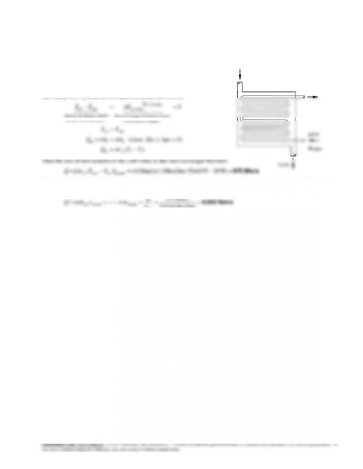
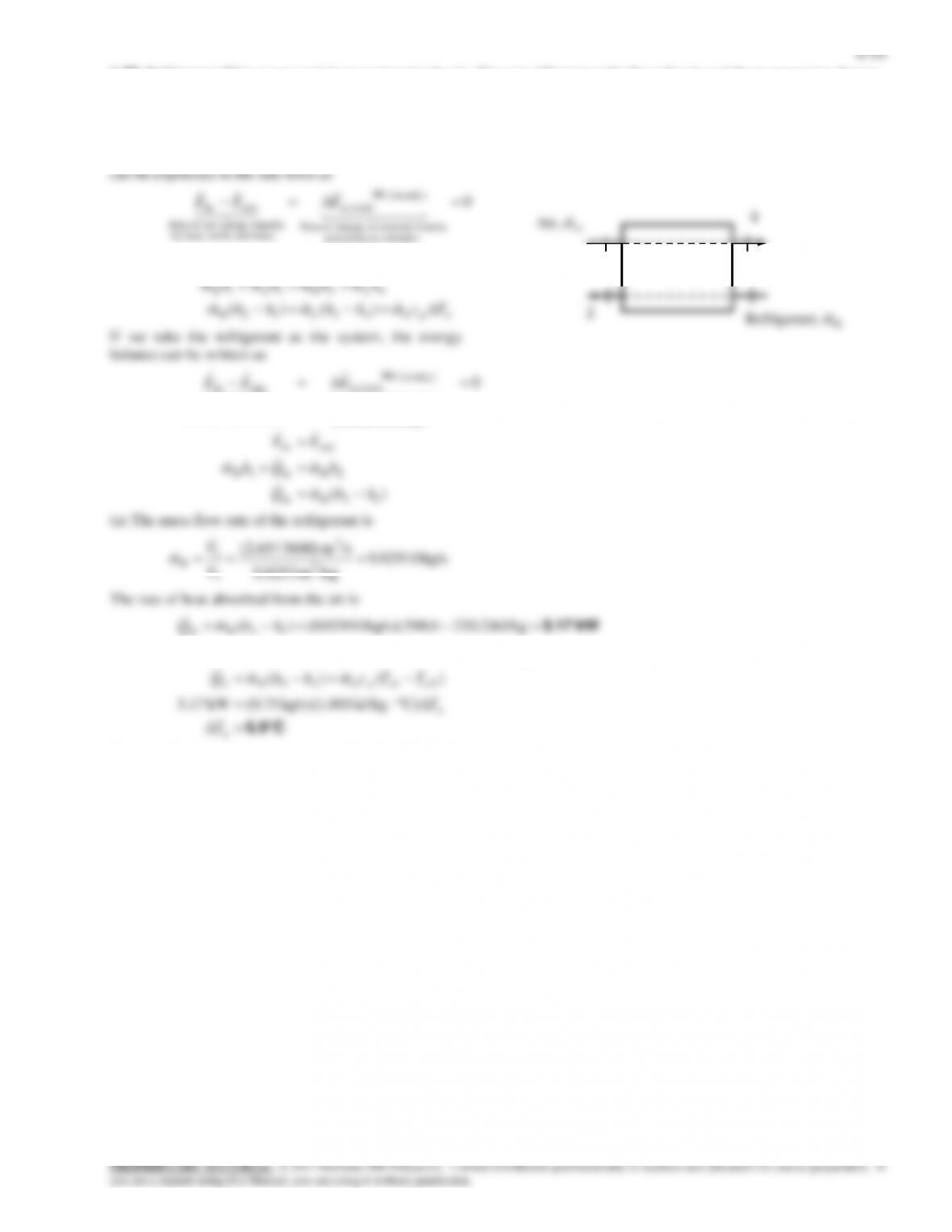
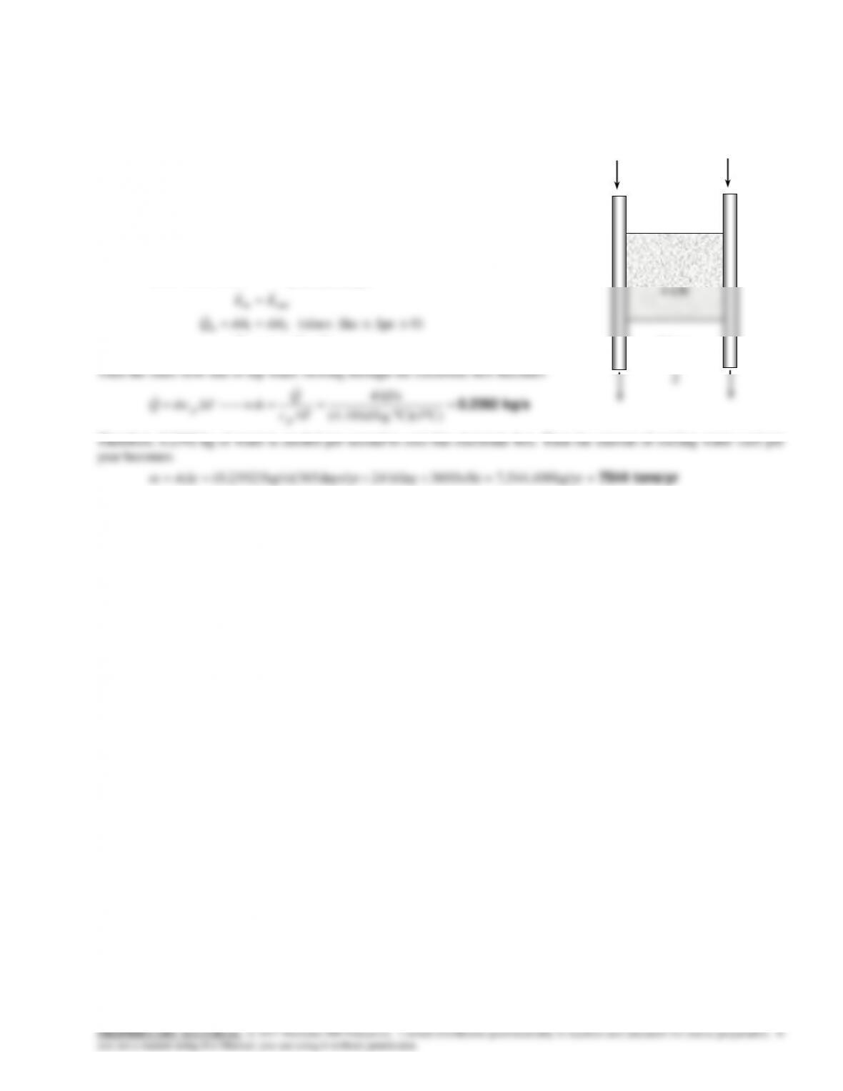
6-85 A sealed electronic box is to be cooled by tap water flowing through channels on two of its sides. The mass flow rate
of water and the amount of water used per year are to be determined.
Assumptions 1 Steady operating conditions exist. 2 Entire heat generated is dissipated by water. 3 Water is an
incompressible substance with constant specific heats at room temperature. 4 Kinetic and potential energy changes are
negligible
Properties The specific heat of water at room temperature is
cp = 4.18 kJ/kg.C (Table A-3).
Analysis We take the water channels on the sides to be the
system, which is a control volume. The energy balance for
this steady-flow system can be expressed in the rate form as
Water
0
energies etc. potential,
kinetic, internal,in change of Rate
(steady) 0
sy stem
mass and work,heat,by
nsferenergy tranet of Rate
outin
EEE
Water
inlet
1
Electronic
box
4 kW
6-59
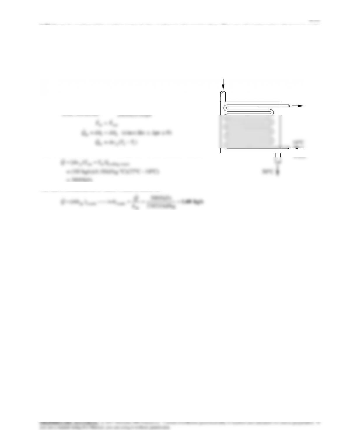
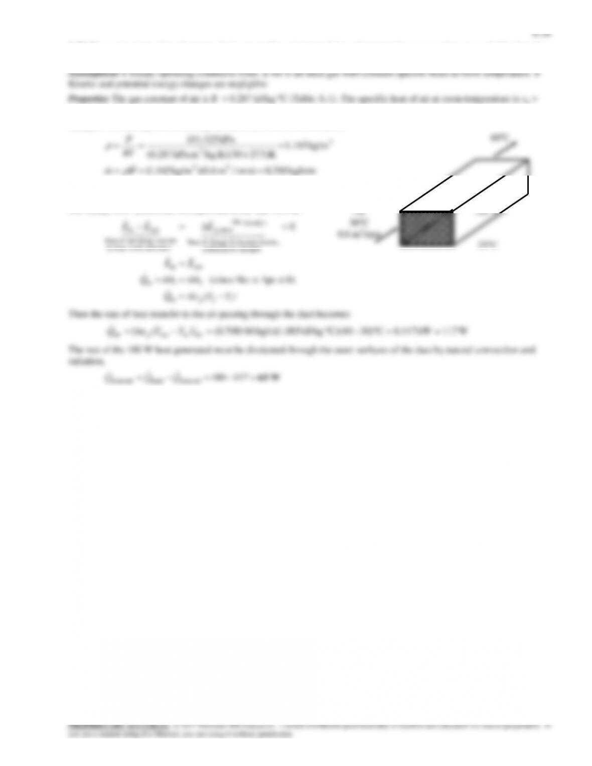
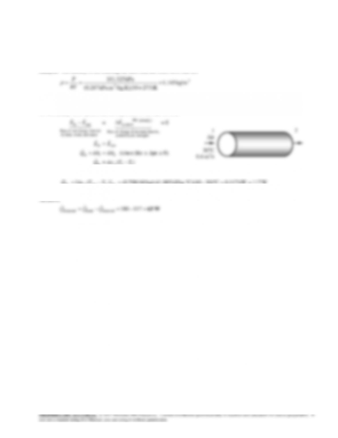
6-87 The components of an electronic device located in a horizontal duct of circular cross section is cooled by forced air.
The heat transfer from the outer surfaces of the duct is to be determined.
Assumptions 1 Steady operating conditions exist. 2 Air is an ideal gas with constant specific heats at room temperature. 3
Kinetic and potential energy changes are negligible
Properties The gas constant of air is R = 0.287 kJ/kg.C (Table A-1). The specific heat of air at room temperature is cp =
1.005 kJ/kg.C (Table A-2).
Analysis The density of air entering the duct and the mass flow rate are
minkg7000min)/m 6.0)(kg/m 165.1(
kg/m 165.1
kPa 325.101
33
3
3
/ .
V
m
P
We take the channel, excluding the electronic components, to be the system, which is a control volume. The energy balance
for this steady-flow system can be expressed in the rate form as
)(
0)peke (since
0
12in
21in
outin
energies etc. potential,
kinetic, internal,in change of Rate
(steady) 0
sy stem
mass and work,heat,by
nsferenergy tranet of Rate
outin
TTcmQ
hmhmQ
EE
EEE
p
Then the rate of heat transfer to the air passing through the duct becomes
W117=kW 117.0C)3040)(CkJ/kg. 005.1)(kg/s 60/700.0()]([ airinoutair TTcmQ p
The rest of the 180 W heat generated must be dissipated through the outer surfaces of the duct by natural convection and
1
Air
30C
0.6 m3/s
2