6-21
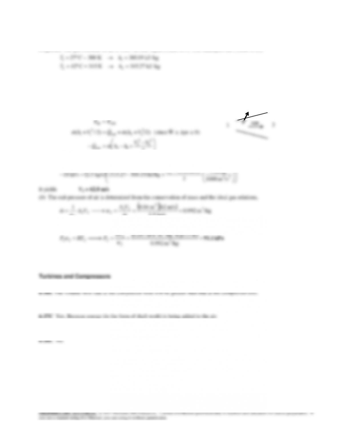
6-35 Air is decelerated in a diffuser from 220 m/s. The exit velocity and the exit pressure of air are to be determined.
Assumptions 1 This is a steady-flow process since there is no change with time. 2 Air is an ideal gas with variable specific
heats. 3 Potential energy changes are negligible. 4 There are no work interactions.
Properties The gas constant of air is 0.287 kPa.m3/kg.K (Table A-1). The enthalpies are (Table A-21)
T h
T h
1 1
2 2
27 300 30019
42 315 27
C = K kJ / kg
C = 315 K kJ / kg
.
.
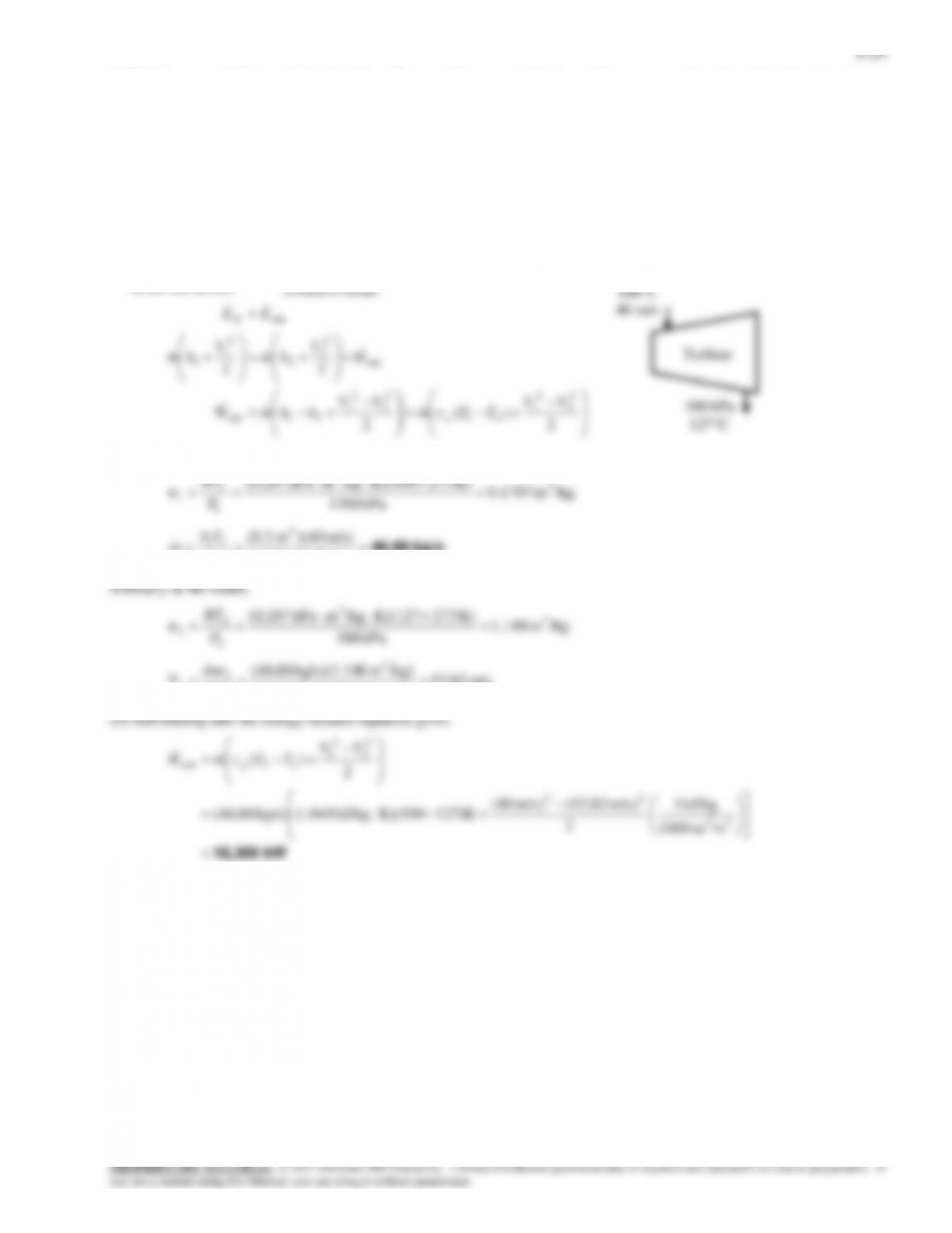
Analysis (a) There is only one inlet and one exit, and thus
m m m
1 2
. We take diffuser as the system, which is a control
volume since mass crosses the boundary. The energy balance for this steady-flow system can be expressed in the rate form
as
outin
energies etc. potential,
kinetic, internal,in change of Rate
(steady) 0
sy stem
mass and work,heat,by
nsferenergy tranet of Rate
outin 0
EE
EEE
2
0)peW (since /2)+()2/(
1
2
12out
2
22out
2
11
hhmQ
VhmQVhm
Substituting, the exit velocity of the air is determined to be
22
2
kJ/kg 1
m/s) (220
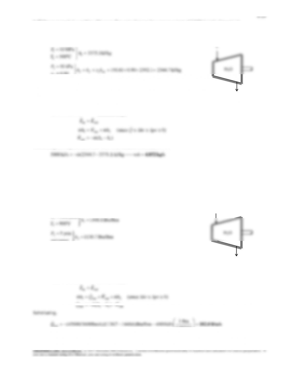
AIR
1
2
18 kJ/s
Assumptions 1 This is a steady-flow process since there is no change with time. 2 Potential energy changes are negligible. 3
The device is adiabatic and thus heat transfer is negligible. 4 Air is an ideal gas with constant specific heats.
Properties The gas constant of air is R = 0.3704 psia.ft3/lbm.R. The constant pressure specific heat of air at the average
temperature of (900 + 300)/2 = 600F is cp = 0.25 Btu/lbm·F (Table A-2a)
PROPRIETARY MATERIAL. © 2017 McGraw-Hill Education. Limited distribution permitted only to teachers and educators for course preparation. If
you are a student using this Manual, you are using it without permission.
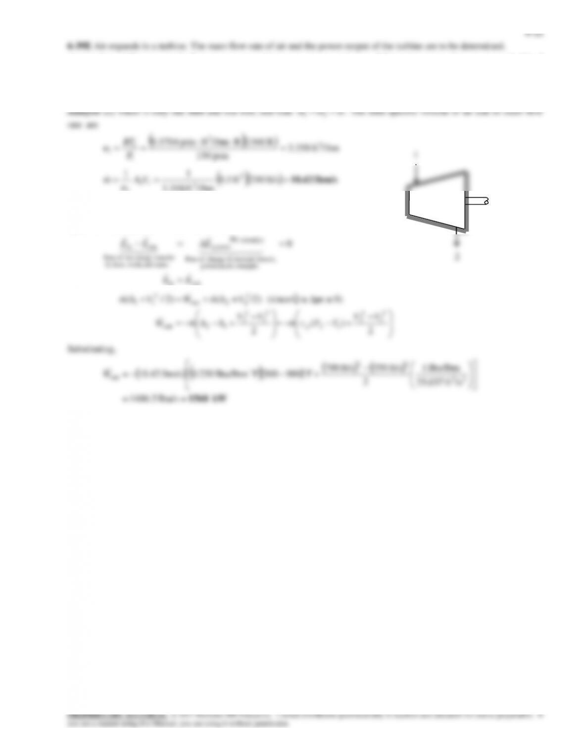
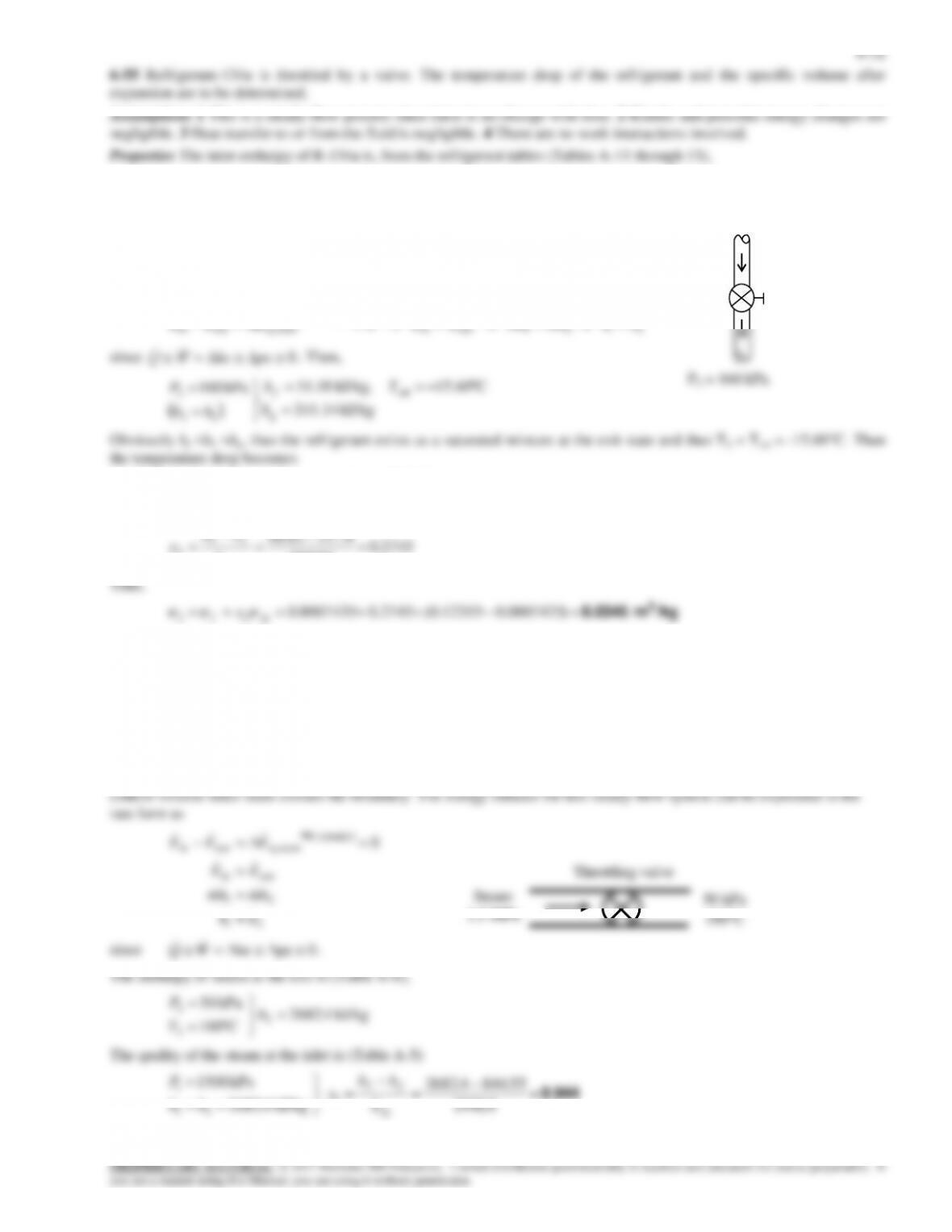
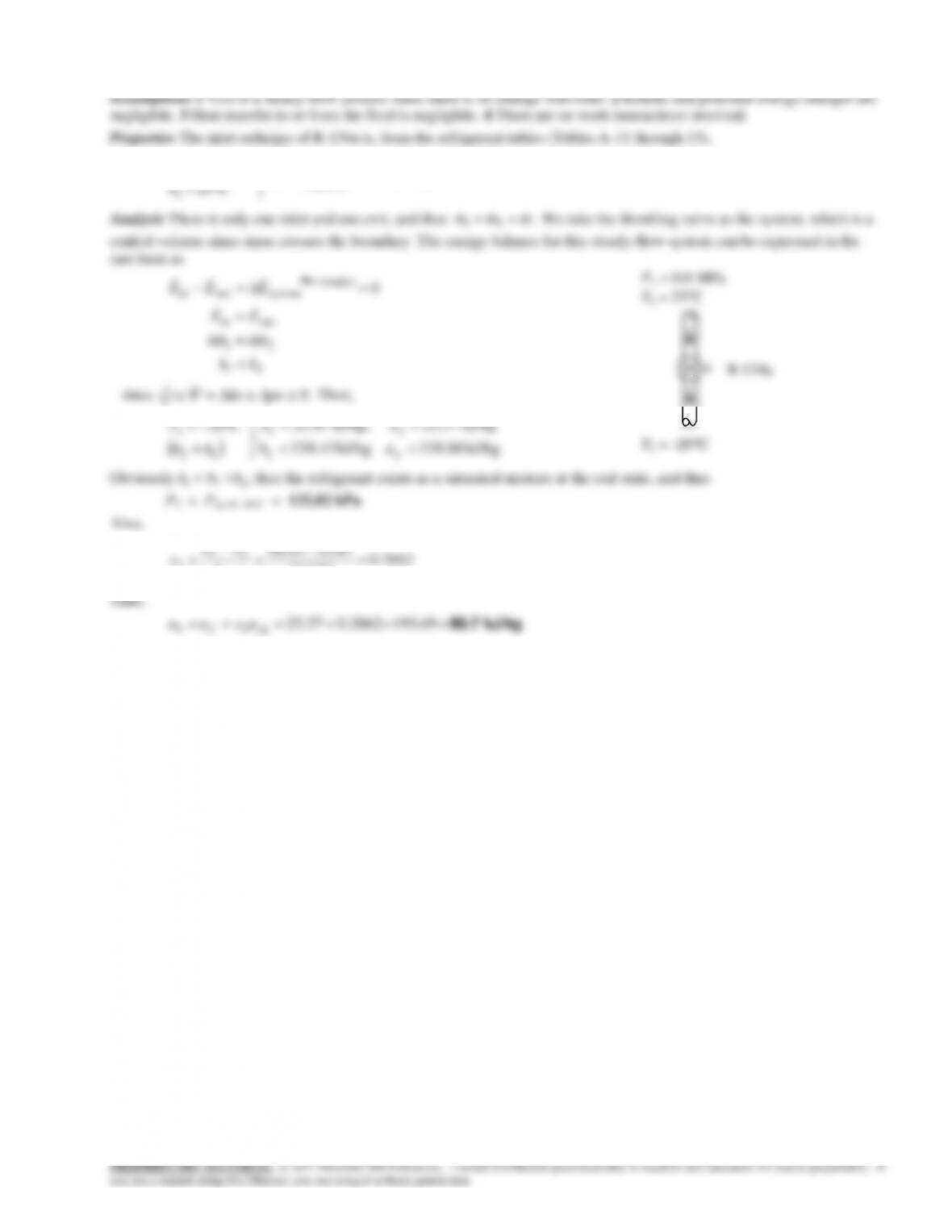
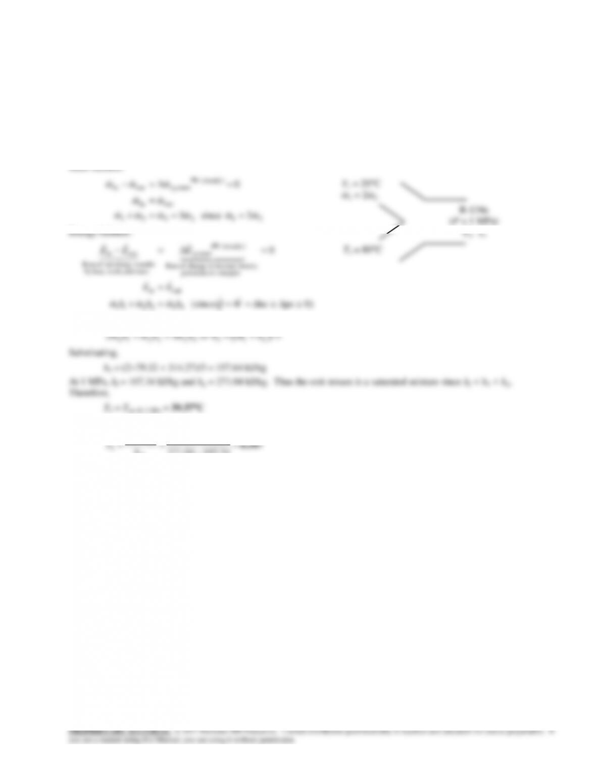
of the refrigerant at the compressor inlet are to be determined.
Assumptions 1 This is a steady-flow process since there is no change with time. 2 Kinetic and potential energy changes are
negligible. 3 The device is adiabatic and thus heat transfer is negligible.
Properties From the refrigerant tables (Tables A-11 through 13)
kJ/kg 235.94
/kgm 0.17398
.
C24
1
3
1
1
h
vaporsat
T
v
kJ/kg .82296
C06
MPa 0.8
2
2
2
h
T
P
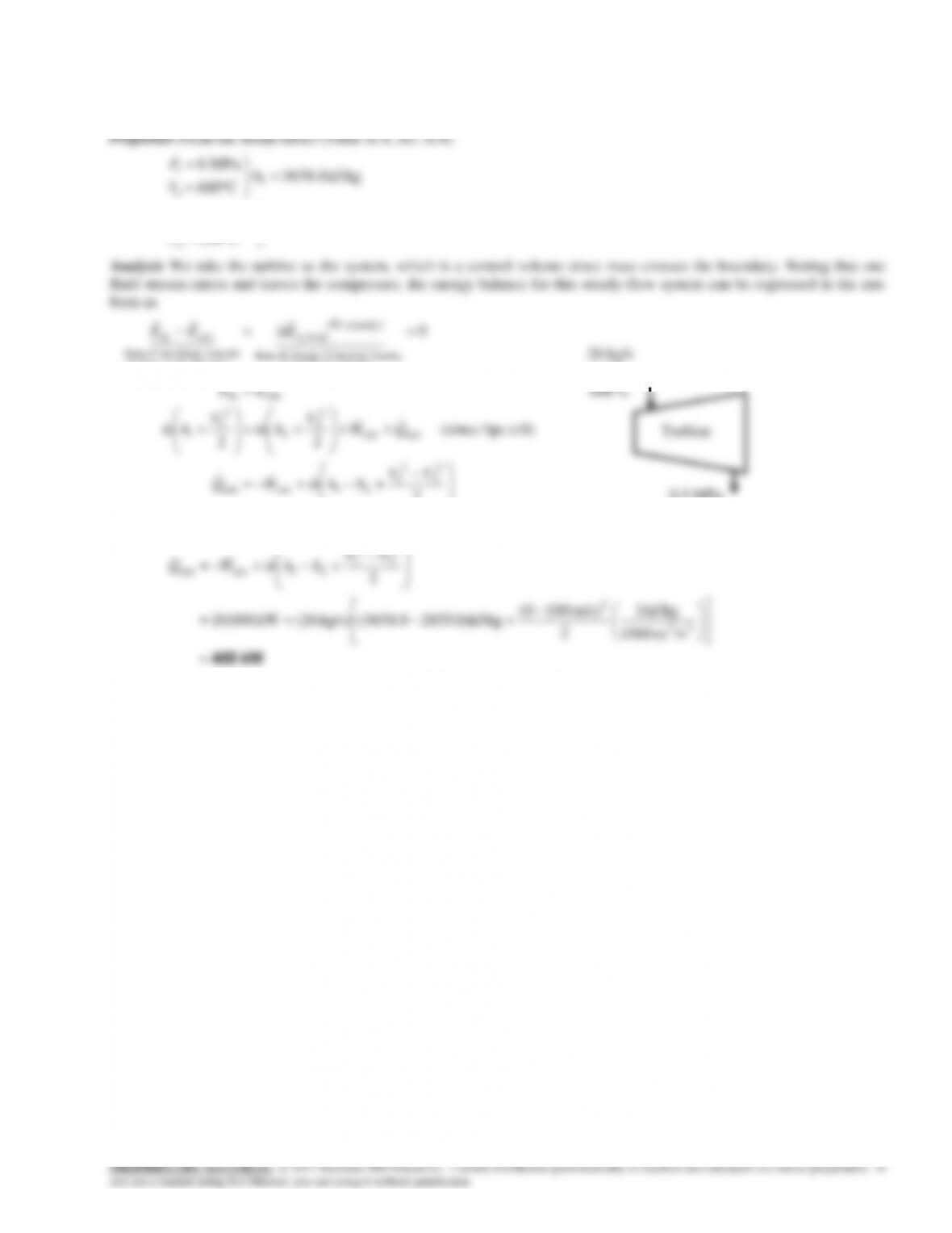
Analysis (a) There is only one inlet and one exit, and thus
m m m
1 2
. We take the
compressor as the system, which is a control volume since mass crosses the boundary. The
energy balance for this steady-flow system can be expressed in the rate form as
outin
energies etc. potential,
kinetic, internal,in change of Rate
(steady) 0
sy stem
mass and work,heat,by
nsferenergy tranet of Rate
outin 0
EE
EEE
( )
W mh mh Q ke pe
W m h h
in
in
(since 0)
1 2
2 1
Substituting,
kJ/s 73.06 kJ/kg235.94296.82kg/s 1.2
in
W
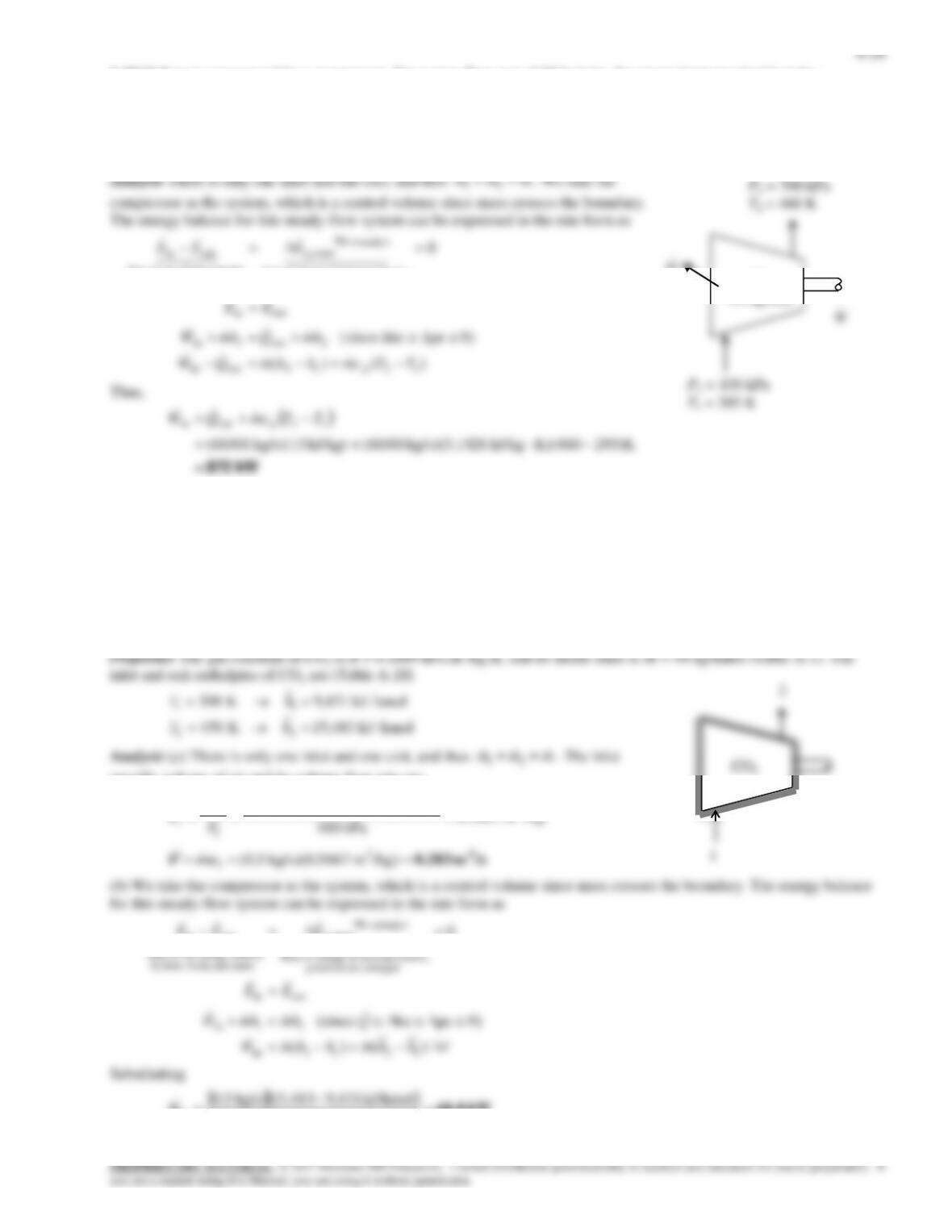
(b) The volume flow rate of the refrigerant at the compressor inlet is
11
R-134a
2
1
6-24
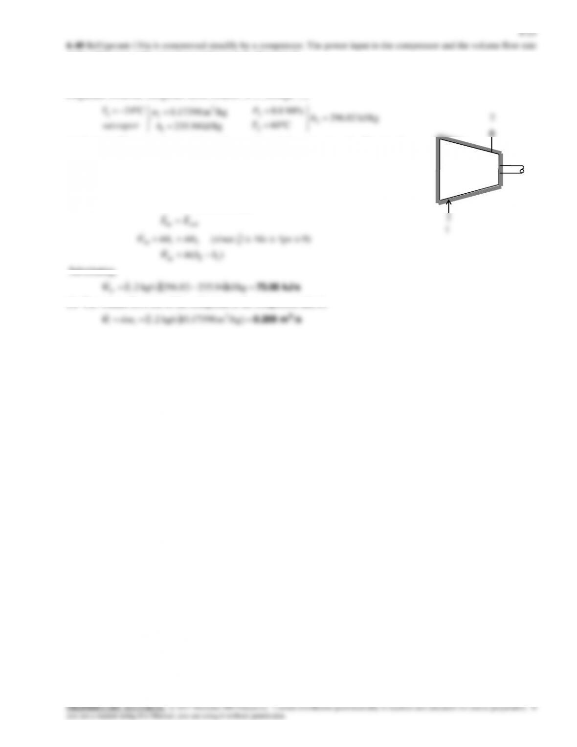
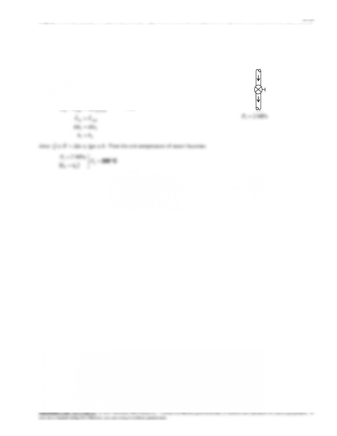
6-41 Saturated R-134a vapor is compressed to a specified state. The power input is given. The exit temperature is to be
determined.
Assumptions 1 This is a steady-flow process since there is no change with time. 2 Kinetic and potential energy changes are
negligible. 3 Heat transfer with the surroundings is negligible.
Analysis We take the compressor as the system, which is a control volume since mass crosses the boundary. Noting that one
fluid stream enters and leaves the compressor, the energy balance for this steady-flow system can be expressed in the rate
form as
0
energies etc. potential,
kinetic, internal,in change of Rate
(steady ) 0
system
mass and work,heat,by
nsferenergy tranet of Rate
outin
EEE
/kgm 1105.0
kJ/kg 90.242
0
kPa 180
3
1
1
1
1
v
h
x
P
The mass flow rate is
kg/s 05283.0
/kgm 0.1104
/sm )60/35.0(
3
3
1
1
v
V
m
Substituting for the exit enthalpy,
kJ/kg 41.287kJ/kg)90.242kg/s)( 05283.0(kW 35.2
)(
22
12in
hh
hhmW
From Table A-13,
C48.9
2
2
2
kJ/kg 41.287
kPa 700 T
h
P
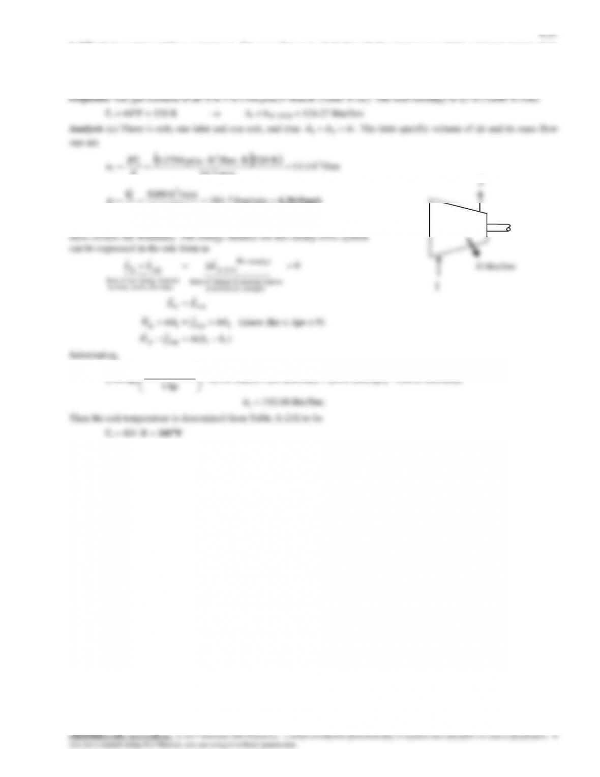
180 kPa
sat. vap.
0.35 m3/min
700 kPa
6-28
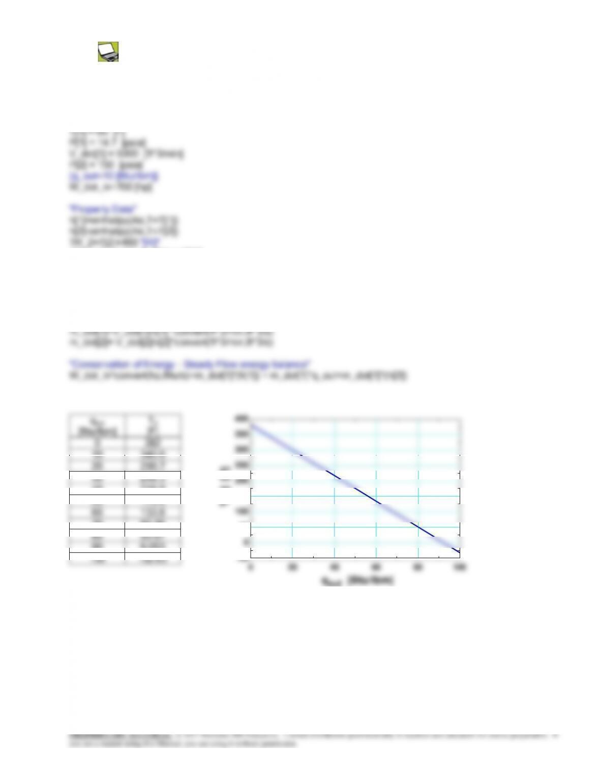
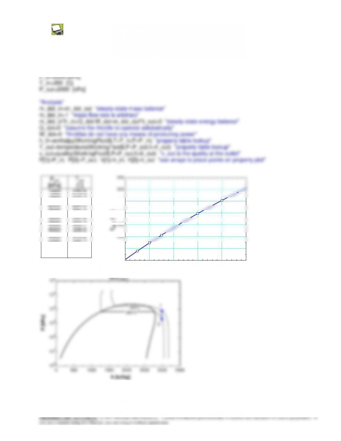
6-47E Problem 6-46E is reconsidered. The effect of the rate of cooling of the compressor on the exit temperature of
air as the cooling rate varies from 0 to 100 Btu/lbm is to be investigated. The air exit temperature is to be plotted against the
rate of cooling.
Analysis The problem is solved using EES, and the solution is given below.
“Knowns “
v[1]=volume(Air,T=T[1],p=P[1])
v[2]=volume(Air,T=T[2],p=P[2])
“Conservation of mass: “
m_dot[1]= m_dot[2]
“Mass flow rate”
6-30
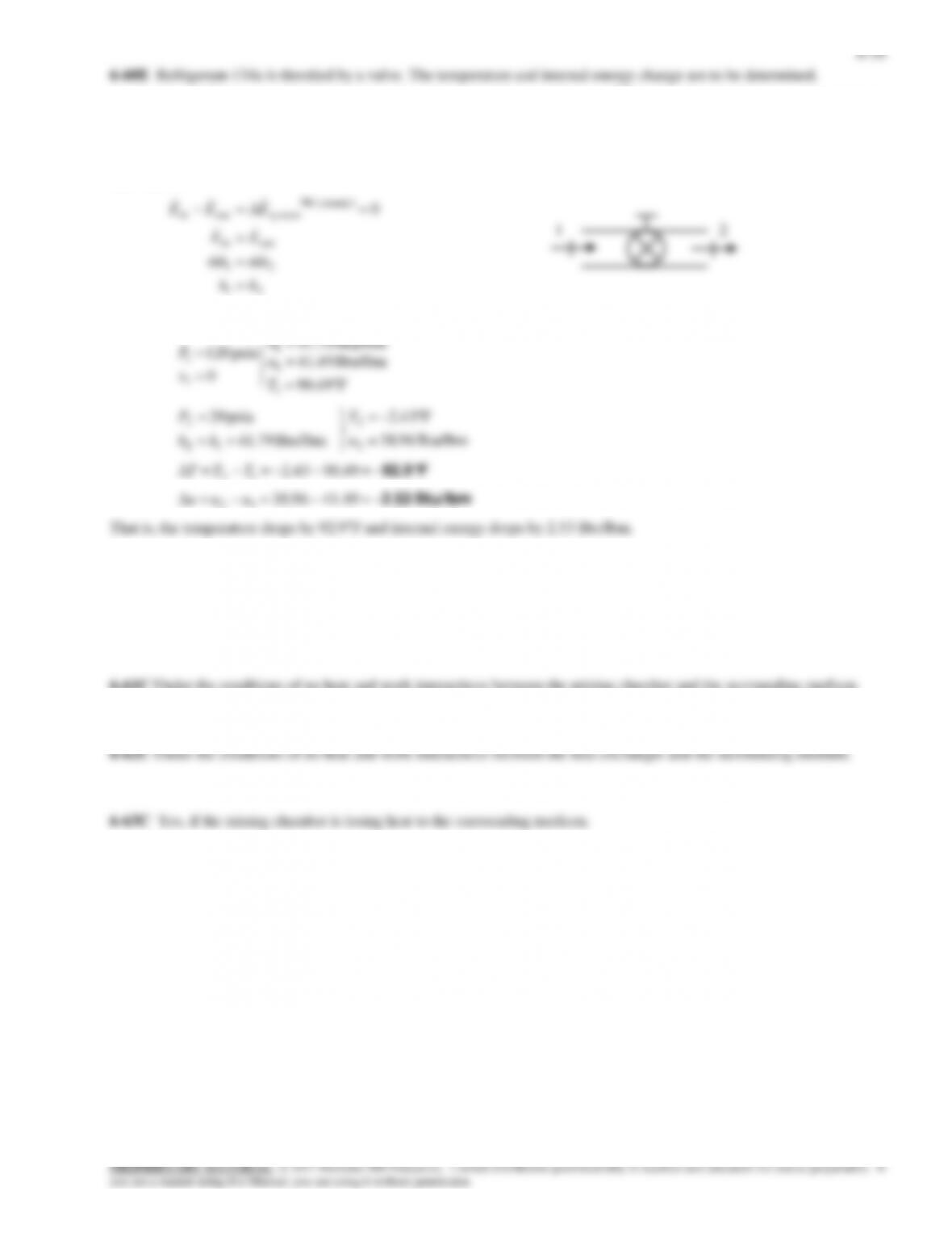
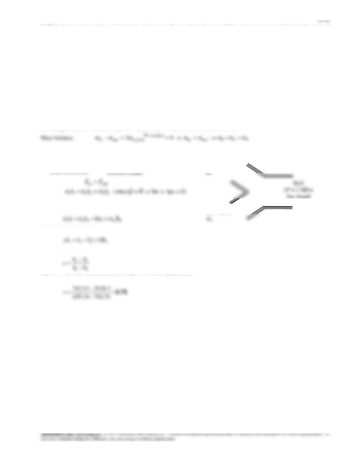
6-49 Steam is expanded in a turbine. The power output is given. The rate of heat transfer is to be determined.
Assumptions 1 This is a steady-flow process since there is no change with time. 2 Kinetic and potential energy changes are
negligible.
kJ/kg 8.2855
C020
MPa 5.0
kJ/kg 3658.8
C060
MPa 6
2
2
2
1
1
1
h
T
P
h
T
P
kJ/kg 28.88
C69.26
liquid sat.
MPa 7.0
1
sat1
1
f
hh
TT
P
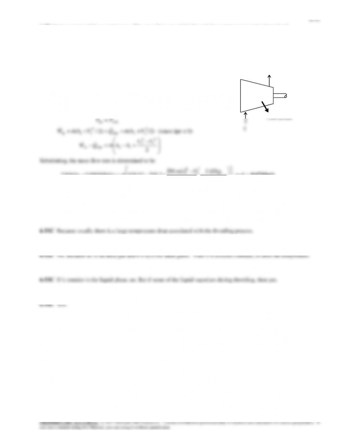
Analysis There is only one inlet and one exit, and thus
m m m
1 2
.
We take the throttling valve as the system, which is a control volume
since mass crosses the boundary. The energy balance for this steady-
flow system can be expressed in the rate form as
0 2121outin
(steady) 0
systemoutin hhhmhmEEEEE
C42.3 69.2660.15
12 TTT
The quality at this state is determined from
2745.0
96.209
18.3182.88
2
2
fg
f
h
hh
x
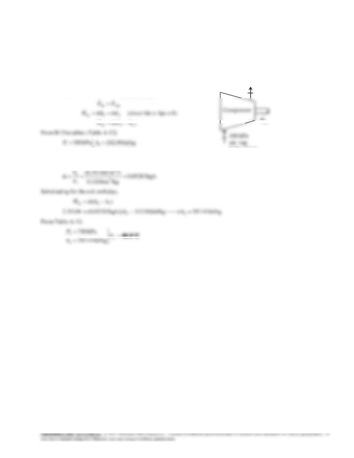
P1 = 700 kPa
Sat. liquid
R-134a
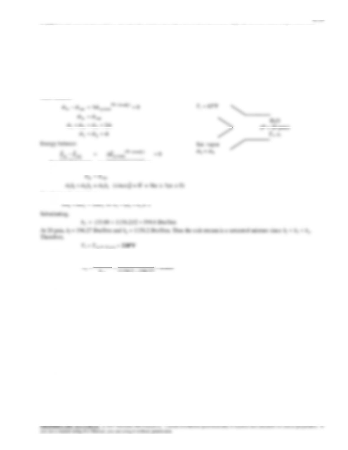
6-33
6-57 Refrigerant-134a is throttled by a valve. The pressure and internal energy after expansion are to be determined.
kJ/kg 86.41
C25
MPa 0.8
C25@
1
1
1
f
hh
T
P
2862.0
96.212
47.2541.86
2
2
fg
f
h
hh
x
22 fgfuxuu
6-35
6-59 Problem 6-58 is reconsidered. The effect of the exit pressure of steam on the exit temperature after throttling as
the exit pressure varies from 6 MPa to 1 MPa is to be investigated. The exit temperature of steam is to be plotted against
the exit pressure.
Analysis The problem is solved using EES, and the solution is given below.
WorkingFluid$=’Steam_iapws’ “WorkingFluid can be changed to ammonia or other fluids”
PROPRIETARY MATERIAL. © 2017 McGraw-Hill Education. Limited distribution permitted only to teachers and educators for course preparation. If
you are a student using this Manual, you are using it without permission.
Assumptions 1 This is a steady-flow process since there is no change with time. 2 Kinetic and potential energy changes are
negligible. 3 Heat transfer to or from the fluid is negligible. 4 There are no work interactions involved.
Analysis There is only one inlet and one exit, and thus
m m m
1 2
. We take the throttling valve as the system, which is a
control volume since mass crosses the boundary. The energy balance for this steady-flow system can be expressed in the
rate form as
0
21
21
outin
(steady) 0
systemoutin
hh
hmhm
EE
EEE
since
Q W ke pe 0
. The properties are (Tables A-11E through 13E),
Btu/lbm 79.41
psia 120
1
1
h
P
Mixing Chambers and Heat Exchangers
6-61C Under the conditions of no heat and work interactions between the mixing chamber and the surrounding medium.
2
1
6-40
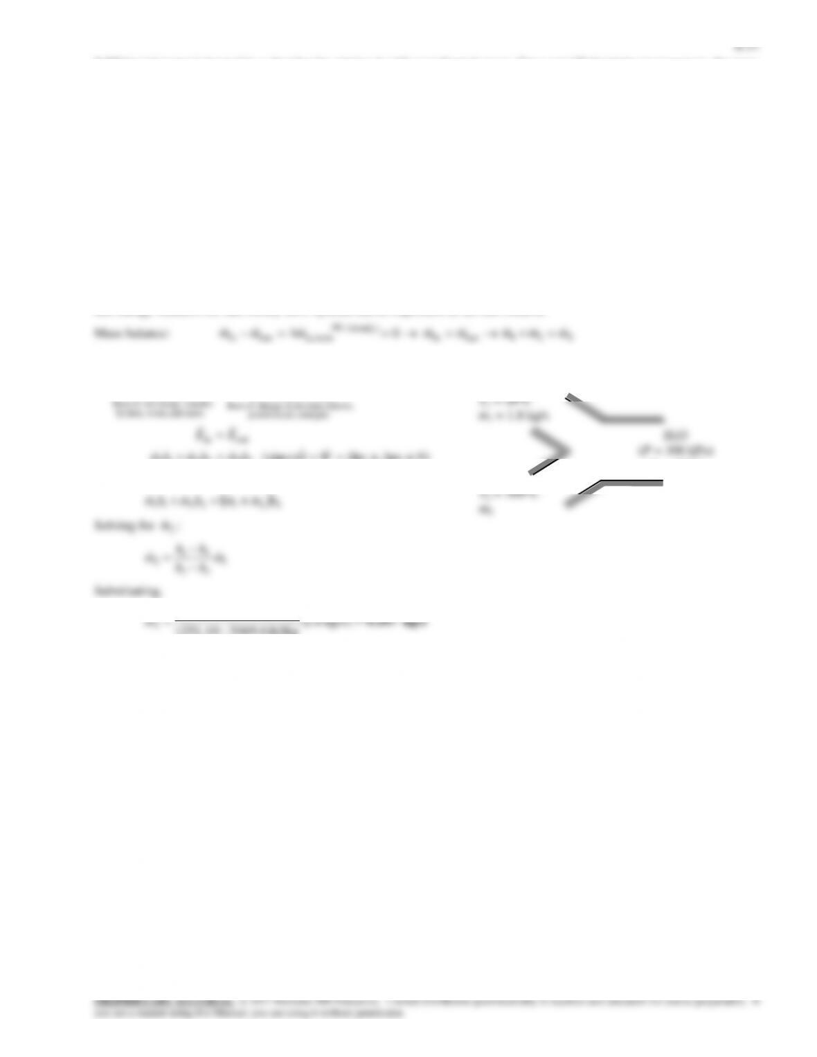
6-67 Two streams of refrigerant-134a are mixed in a chamber. If the cold stream enters at twice the rate of the hot stream,
the temperature and quality (if saturated) of the exit stream are to be determined.
Assumptions 1 This is a steady-flow process since there is no change with time. 2 Kinetic and potential energy changes are
negligible. 3 There are no work interactions. 4 The device is adiabatic and thus heat transfer is negligible.
Properties From R-134a tables (Tables A-11 through A-13),
h1 hf @ 20C = 79.32 kJ/kg
h2 = h @ 1 MPa, 80C = 314.27 kJ/kg
Analysis We take the mixing chamber as the system, which is a control volume since mass crosses the boundary. The mass
and energy balances for this steady-flow system can be expressed in the rate form as
Mass balance:
212321
outin
(steady ) 0
systemoutin
2 since 3
0
mmmmmm
mm
mmm
Energy balance:
0)peke (since
0
332211
outin
energies etc. potential,
kinetic, internal,in change of Rate
(steady) 0
system
mass and work,heat,by
nsferenergy tranet of Rate
outin
WQhmhmhm
EE
EEE
Combining the two gives
3/232 213322212 hhhorhmhmhm
Substituting,
h3 = (279.32 + 314.27)/3 = 157.64 kJ/kg
At 1 MPa, hf = 107.34 kJ/kg and hg = 271.04 kJ/kg. Thus the exit stream is a saturated mixture since hf < h3 < hg.
Therefore,
T3 = Tsat @ 1 MPa = 39.37C
and
34.10764.157
3
f
hh
R-134a
(P = 1 MPa)
T3, x3
T2 = 80C
T1 = 20C
m1 = 2m2
·
·